US2349385A - Tray tier support - Google Patents
Tray tier support Download PDFInfo
- Publication number
- US2349385A US2349385A US466044A US46604442A US2349385A US 2349385 A US2349385 A US 2349385A US 466044 A US466044 A US 466044A US 46604442 A US46604442 A US 46604442A US 2349385 A US2349385 A US 2349385A
- Authority
- US
- United States
- Prior art keywords
- tray
- trays
- bolt
- post
- tier
- Prior art date
- Legal status (The legal status is an assumption and is not a legal conclusion. Google has not performed a legal analysis and makes no representation as to the accuracy of the status listed.)
- Expired - Lifetime
Links
- 238000000926 separation method Methods 0.000 description 4
- 240000004282 Grewia occidentalis Species 0.000 description 3
- 239000002023 wood Substances 0.000 description 2
- 230000015572 biosynthetic process Effects 0.000 description 1
- 229960001948 caffeine Drugs 0.000 description 1
- 239000007799 cork Substances 0.000 description 1
- 230000000694 effects Effects 0.000 description 1
- 125000006850 spacer group Chemical group 0.000 description 1
- 230000002459 sustained effect Effects 0.000 description 1
- RYYVLZVUVIJVGH-UHFFFAOYSA-N trimethylxanthine Natural products CN1C(=O)N(C)C(=O)C2=C1N=CN2C RYYVLZVUVIJVGH-UHFFFAOYSA-N 0.000 description 1
Images
Classifications
-
- A—HUMAN NECESSITIES
- A47—FURNITURE; DOMESTIC ARTICLES OR APPLIANCES; COFFEE MILLS; SPICE MILLS; SUCTION CLEANERS IN GENERAL
- A47B—TABLES; DESKS; OFFICE FURNITURE; CABINETS; DRAWERS; GENERAL DETAILS OF FURNITURE
- A47B21/00—Tables or desks for office equipment, e.g. typewriters, keyboards
- A47B21/04—Tables or desks for office equipment, e.g. typewriters, keyboards characterised by means for holding or fastening typewriters or computer equipment
- A47B21/045—Fastening means for paper sheet; Paper trays; Accessories for typists, e.g. line indicators
Definitions
- This invention is concerned with a support for desk trays that are to be built up into a tier.
- the trays for which the present supports are designed are of the usual type for use on desks, counters, cabinets, etc.-, adapted to containyarious papers which may be placed therein or'removed therefrom from time to time.
- These trays commonly made of wood, are often'arranged in spaced relation one over another in tier formation, two high or more.
- To sustain the tier of trays various expedients have been worked out, most of them involving spring clips which assist in holding the associated supports in place, but none of them being wholly satisfactory.
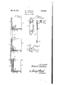
- Figure 1 is a vertical sectional view, taken on line Il' of Fig. 3, showing a tier of three trays interconnected by the supports of this invention;
- Fig.3 is a horizontal sectional View, taken on line3+3 of Fig. 1.
- the trays .of which three are in the tier shown in Fig. 1 may each consist of a bottom B from which rises a pair of ends E and a pair of sides S (one only of the ends and sides being illustrated) and all interconnected in any suitable way to render the structure rigid and sturdy.
- afoot 5, of cork, felt or the like may be afiixed to the under face of the bottom, one adjacent each corner thereof.
- a set -'of relatively small holes 6 extend through the tray bottom; one slightly tothe outside of each'foot and slightly to the inside of the angle formed by the inner faces of a the sides and 'ends whereby opposite ends of the four holeswill be fully exposed on the upper and under faces of the bottom.
- Each support set (see Fig. 2) consists of a post in the form of an angle plate affording walls l and II in right angular relation betv'veen which are carried upper and lower -led'ges'lZ and
- the bolt is also formed, by preference, with a plurality of radially extended teeth 23; four being illustrated, all in a common plane at a point lengthwise of the bolt'which is opposite an end and side of the tray (when assembled therewith) slightlybelow their top edges.
- the ends of the angled walls of the post may be curved, sloped, or otherwise formed to produce an effect pleasing to the eye, one suggestivedesign being indicated in Fig. 2.
- the four supports are assembled therewith in the mannershown for one corner thereof in Fig. 1.
- the angle post is placed over the outside corner of a, lower tray, the exterior face of the meeting end and side being engaged by the walls l0 and II.
- the bolt is inserted through the tray, bottom hole 6 and two registering apertures or holes 25 and 26 in the lower and upper ledges l3 and I2, respectively, the lower hole being of a size tofreely receive the bolt, and the upper hole only the threaded stem extending beyond the upper end thereof, and through the hole 6 in the bottom of a second tray to project upwardly therewithin.
- the lower ledge which desirably remains spaced from the top edge of' the tray corner therebelow to accommodate itself to trayshaving walls of nonuniform height, afiords' a bearing for the bolt whereby the post as a whole is maintained in vertical alignment therewith and with the ends and sides of the tray each ,ofwhich also. main-, tained in vertical registerfwiththe wallsiofnthe other trays in the .same.tier'.
- 'lfa thirdit ray is also to be added to the tier,'then another bolt with angle post threaded thereon "is' screw threadedendwise to the bolt extendingjupwardly from the bottom tray, a support upontheupper ledge l2 ofthesecond strutbeinglthe reby afforded for 'the third. tray; av n 'i completed the build-up oftraysfor the tier,.,a..c'ap nut, such as theone denoted as l8, is'applied over on the outside in cooperation with the bolt whose.
- teeth are adapted to engage the tray corners on the inside. It may be that the thickness of the tray walls do not always ,run uniform, or
- the holes 6 in the tray bottom- mayflnot always be located a, uniform distance from the tray walls, and to meet such contingencies the bolt teeth may, with slight effort, be fsunklinto the tray walls to whatever extent is necessary, to provide for each bolt a requisite bracing relative thereto.
- the bolt teeth may, with slight effort, be fsunklinto the tray walls to whatever extent is necessary, to provide for each bolt a requisite bracing relative thereto.
- the assembly is completed by application of .thebolt endfittings whereby to clamp the. top and bottom trays (together with any trays intermediately thereof) into unitary relation.
- the entire tierv of trays is then joined immovably and inseparably so as to be ready for sustained and active use.
- a tray one or more is, to be added to the tier, or subtracted therefrom, it is-necessary merel that the cap nuts be removed for receiving the added supports and trays, or for taking away the supports and trays no longer needed, the operation being completed by again restoring the bolt end fittings to clamping positions within the topmost tray where they may then be reconnected with the upper ends of the several bolts (or interconnected bolts, as the case may be)
- the tray support hereindescribed is advantageous in that it makes for a firm and stable tier structure. It is also simple to apply and use, and accommodates itself to non-uniform conditions such as differences in tray heights, wall thicknesses, etc.
- the fittings at opposite ends of the rods or bolts are so small as not to mar the wood or to interfere with the tray contents, and if desired may be formed to occupy positions within counter-sunk openings wherein they will lie flush with the adjacent faces of the trays.
- the post walls extend endwise beyond the two ledges, thereby assuring engagement with the tray corners for a. sufficient distance to afford stability to the tier structure as a whole.
- each corner support comprising an angle post'engageable fiatwisewith exterior faces of two adjacent walls, of an upper and lower tray'for maintaining one in vertical register with the other, there being through each tray bottom a corner hole adjacent the inner faces of the tray walls aforesaid, a pair of spaced ledges carried by the angle post at points spaced from the ends thereof, between two trays, one of the ledges affording 'supportfor the bottom of the tray thereabove and.
- both of the t ledges being This end is attained formed therethrough with holes in register with each other and with the holes in the tray corners, and means for securing the post in a fixed position exteriorly of the registerin corners of the superposed trays comprising a bolt extending vertically through the holes thereof and of the post ledges and provided near its upper end with means in engagement with the ledge thereabove, and bolt end fittings atopposite ends of the bolt adjustable relatively toward and from each other and engageable with opposite faces of the tray bottoms to exert a clamping force thereon whereby-to interconnect the trays with the supporting post therebetween as an immovable unit.
- corner supports each comprising an angle post engageable flatwise with exterior faces of two. adjacent walls of an upper and lower tray for maintaining one in vertical register with the'othen'there being through each tray bottom a corner-hole adjacent' thein'ner' faces of the tray walls aforesaid,' a,pair of spaced, ledges carried by the angle post spaced from the ends thereof at points between two trays, one of the ledges affording support for the bottom of .the tray-thereabovaand means for securing the post in a fixed position exteriorly of the registering corners of the superposed trays comprising a bolt extending vertically through the holes in thebottom of the tray, and means on the ledges'connected with the bolt and provided near its upper end with supporting means in engagement with the ledge thereabove, and means at opposite ends of the'bolt adjustable relativelyx toward and from each other and engageable withthe trays to exert a, clamping force thereon whereby to interconnect
- a bolt extended between; the bottoms thereof to space one from the other. a fixed distance, a post extending from one tray to the other on the outside of the bolt having means adjacent opposite ends for engagement with an exterior corner of each tray, means connecting, with the bolt-ends in; engagement with the bottoms o f the trays; adapted to prevent separation; of one tray from the other, spaced means e tmqi eiewa lv-irQm the ost at points s ce .r.
- supports between the trays each comprising an angle post extended from one tray to the other and in engagement with an exterior corner of each tray, a bolt extended vertically between the trays close to the inside corners thereof and connected to each to prevent separation thereof, spaced means interconnecting the post and bolt at points between the two trays, and means extended outwardly from the bolt for engagement with inner faces of the tray walls to maintain the bolt in spaced relation thereto.
- supports between the trays each comprising an angle post extended from one tray to the other and in engagement with an exterior corner of each tray, a bolt extended vertically between the trays close to the inside comers thereof and connected to each to prevent separation thereof, spaced means interconnecting the post and bolt at points between the two trays, and spaced means extended outwardly from the bolt for engagement with inner faces of the tray walls at points varying in distance from the bolt axis according to the rotative position of the bolt, whereby to maintain the bolt in adjustable spaced relation to the proximate tray corner.
- corner supports each comprising an angle post engageable exteriorly with corners of upper and lower trays, there being through each tray bottom a corner hole adjacent the inner face of the corner, spaced means having apertures and extending transversely of the angle post to the inside thereof at points spaced from the ends of the posts, the upper of said means afiording support for the upper tray when rested thereon, and means for locking the post in a fixed position of engagement with the corners of registering upper and lower trays comprising a bolt extending vertically through the holes thereof and in looking engagement with the apertures of said spaced means inwardly of the angle post and abutting the underside of the upper of said spaced means.
- corner supports between the trays each comprising a post extending from one tray to the other and having means adjacent opposite ends for engagement with an exterior corner of each tray, spaced ledges between the trays extending inwardly from the post at points spaced from the ends thereof, one of the ledges engaging with the upper tray to afiord a sustaining support therefor, and a bolt located interiorly of the corner post and extending from the lower tray to th upper tray and abutting the upper ledge and the bottom of the lower tray, said ledges having means slidably receiving the bolt and connecting them to the same, and means connecting opposite ends of the bolt to the proximate trays to unite the tier of trays immovably.
Landscapes
- Engineering & Computer Science (AREA)
- Computer Hardware Design (AREA)
- General Engineering & Computer Science (AREA)
- Tables And Desks Characterized By Structural Shape (AREA)
Description
May 23, 1944. w. L. SNELLING 2,349,385
' TRAY TIER SUPPORT Filed Nov. 18, 1942 Patented May 23, 1944 TRAY TIER SUPPORT Walter L. Snelling, Chicago, Ill., assignor to Horders, Incorporated, Chicago, 111., a corporation of Illinois 7 Application November 18, 1942, Serial No. 466,044
9 Claims. (c1. 211 -126) This invention is concerned with a support for desk trays that are to be built up into a tier.
The trays for which the present supports are designed are of the usual type for use on desks, counters, cabinets, etc.-, adapted to containyarious papers which may be placed therein or'removed therefrom from time to time. These trays, commonly made of wood, are often'arranged in spaced relation one over another in tier formation, two high or more. To sustain the tier of trays various expedients have been worked out, most of them involving spring clips which assist in holding the associated supports in place, but none of them being wholly satisfactory. With a view to providing interconnecting supports which are simple, inexpensive, easily fitted in place, and furnish a stable inseparable support for the various'trays comprised in the tier, the present improvements have been developed. A suggestive embodiment of my invention is set forth in the accompanying drawing wherein:
Figure 1 is a vertical sectional view, taken on line Il' of Fig. 3, showing a tier of three trays interconnected by the supports of this invention;
Fig. 2 is a perspective view of the four'elements, disassembled, =which together make up one of the supports; and
Fig.3 is a horizontal sectional View, taken on line3+3 of Fig. 1.
The trays .of which three are in the tier shown in Fig. 1 may each consist of a bottom B from which rises a pair of ends E and a pair of sides S (one only of the ends and sides being illustrated) and all interconnected in any suitable way to render the structure rigid and sturdy. If desired afoot 5, of cork, felt or the like, may be afiixed to the under face of the bottom, one adjacent each corner thereof. For application of the supports presently to be described a set -'of relatively small holes 6 extend through the tray bottom; one slightly tothe outside of each'foot and slightly to the inside of the angle formed by the inner faces of a the sides and 'ends whereby opposite ends of the four holeswill be fully exposed on the upper and under faces of the bottom.
- To sustain one tray in spaced relation above another, a'set of four supports are employed, one for each corner. Each support set (see Fig. 2) consists of a post in the form of an angle plate affording walls l and II in right angular relation betv'veen which are carried upper and lower -led'ges'lZ and |3,'r(-: spectively; a rod or bolt id having at its lower end a threaded socket ,l andat its upper'end a threadedstem It or reduced diameter formingat its juncture with the bolt anannular shoulder H; a cap nut I8 havinga threaded socket 19 to receive the stem l6, and formed atone end with a slot 20 forreception of a screw-driver blade; and a base screw comprising a slotted head 2| from which extends a threaded shank 22 adapted to be .received cooperatively within the socket l5 of the bolt. The bolt is also formed, by preference, with a plurality of radially extended teeth 23; four being illustrated, all in a common plane at a point lengthwise of the bolt'which is opposite an end and side of the tray (when assembled therewith) slightlybelow their top edges. The ends of the angled walls of the post may be curved, sloped, or otherwise formed to produce an effect pleasing to the eye, one suggestivedesign being indicated in Fig. 2.
To erect and sustain a tier of trays, the four supports are assembled therewith in the mannershown for one corner thereof in Fig. 1. Here it will be observed the angle post is placed over the outside corner of a, lower tray, the exterior face of the meeting end and side being engaged by the walls l0 and II. When thus fitted, the bolt is inserted through the tray, bottom hole 6 and two registering apertures or holes 25 and 26 in the lower and upper ledges l3 and I2, respectively, the lower hole being of a size tofreely receive the bolt, and the upper hole only the threaded stem extending beyond the upper end thereof, and through the hole 6 in the bottom of a second tray to project upwardly therewithin. This second tray-finds support upon the top face of the upper ledge 12 of the angle post which itself is supported at a fixed elevation by engagement of the bolt shoulderv ll with the under face of the same ledge. The lower ledge which desirably remains spaced from the top edge of' the tray corner therebelow to accommodate itself to trayshaving walls of nonuniform height, afiords' a bearing for the bolt whereby the post as a whole is maintained in vertical alignment therewith and with the ends and sides of the tray each ,ofwhich also. main-, tained in vertical registerfwiththe wallsiofnthe other trays in the .same.tier'. 'lfa thirdit ray is also to be added to the tier,'then another bolt with angle post threaded thereon "is' screw threadedendwise to the bolt extendingjupwardly from the bottom tray, a support upontheupper ledge l2 ofthesecond strutbeinglthe reby afforded for 'the third. tray; av n 'i completed the build-up oftraysfor the tier,.,a..c'ap nut, such as theone denoted as l8, is'applied over on the outside in cooperation with the bolt whose.
teeth are adapted to engage the tray corners on the inside. It may be that the thickness of the tray walls do not always ,run uniform, or
that the holes 6 in the tray bottom-mayflnot always be located a, uniform distance from the tray walls, and to meet such contingencies the bolt teeth may, with slight effort, be fsunklinto the tray walls to whatever extent is necessary, to provide for each bolt a requisite bracing relative thereto. ,In one, rotative,,-,positiong of thebolt two of .thefour teethextend directly toward the facing walls of the tray, and so tend to space the bolt further removed therefrom, than if the bolt be rotated to another position, say through 45, wherein the teeth are disposed angularly to such walls, permitting the bolt then to occupy a position closer to thetray corner. With the bolt, or two or more interconnectedboltslfitted inplace, as already described, the assembly is completed by application of .thebolt endfittings whereby to clamp the. top and bottom trays (together with any trays intermediately thereof) into unitary relation. The entire tierv of trays is then joined immovably and inseparably so as to be ready for sustained and active use. At any time that a tray (one or more) is, to be added to the tier, or subtracted therefrom, it is-necessary merel that the cap nuts be removed for receiving the added supports and trays, or for taking away the supports and trays no longer needed, the operation being completed by again restoring the bolt end fittings to clamping positions within the topmost tray where they may then be reconnected with the upper ends of the several bolts (or interconnected bolts, as the case may be) I The tray support hereindescribed is advantageous in that it makes for a firm and stable tier structure. It is also simple to apply and use, and accommodates itself to non-uniform conditions such as differences in tray heights, wall thicknesses, etc. The fittings at opposite ends of the rods or bolts are so small as not to mar the wood or to interfere with the tray contents, and if desired may be formed to occupy positions within counter-sunk openings wherein they will lie flush with the adjacent faces of the trays. The post walls extend endwise beyond the two ledges, thereby assuring engagement with the tray corners for a. sufficient distance to afford stability to the tier structure as a whole.
I claim:
1. For use with a tier of like desk trays having vertical walls, fourcorner supports each comprising an angle post'engageable fiatwisewith exterior faces of two adjacent walls, of an upper and lower tray'for maintaining one in vertical register with the other, there being through each tray bottom a corner hole adjacent the inner faces of the tray walls aforesaid, a pair of spaced ledges carried by the angle post at points spaced from the ends thereof, between two trays, one of the ledges affording 'supportfor the bottom of the tray thereabove and. both of the t ledges being This end is attained formed therethrough with holes in register with each other and with the holes in the tray corners, and means for securing the post in a fixed position exteriorly of the registerin corners of the superposed trays comprising a bolt extending vertically through the holes thereof and of the post ledges and provided near its upper end with means in engagement with the ledge thereabove, and bolt end fittings atopposite ends of the bolt adjustable relatively toward and from each other and engageable with opposite faces of the tray bottoms to exert a clamping force thereon whereby-to interconnect the trays with the supporting post therebetween as an immovable unit.
2. For use with a tier of like desk trays having vertical walls, four corner supports each comprising an angle post engageable flatwise with exterior faces of two. adjacent walls of an upper and lower tray for maintaining one in vertical register with the'othen'there being through each tray bottom a corner-hole adjacent' thein'ner' faces of the tray walls aforesaid,' a,pair of spaced, ledges carried by the angle post spaced from the ends thereof at points between two trays, one of the ledges affording support for the bottom of .the tray-thereabovaand means for securing the post in a fixed position exteriorly of the registering corners of the superposed trays comprising a bolt extending vertically through the holes in thebottom of the tray, and means on the ledges'connected with the bolt and provided near its upper end with supporting means in engagement with the ledge thereabove, and means at opposite ends of the'bolt adjustable relativelyx toward and from each other and engageable withthe trays to exert a, clamping force thereon whereby to interconnect the trays withthe supporting post there between as an immovable unit. 7' v i 3; For use with a tier of like desk trays having vertical walls-four corner's'upports each comprising an angle-post engageable exteriorlywith corners'of' upper'and lower trays, there being through each tray bottom a cornerhole adjacent the inner faces of the comer, a pair of spaced ledges carried by the angle'post at points spaced from, the ends. thereof. between two trays,'-one of the ledges affording" support for-the tray thereabove when rested thereupon and both of the ledges being formed thereth'rough with holes in register .with each other and with the holes in-the"tray corners, a. bolt extended verticallythrough the ledge holes .andintmengagement with the proximate face of the "bottom ofthe tray'therebelow, and having near its top means engageable with thetunder face" of the upper ledge whereby tov serve as a spacer betweenthe two trays, and .screw means engageable'wi'th the remote faces of the tray bottoms and removablyv and adjustably, connected to' opposite ends of the bolt adapted to exert upon thetrays a clamping force whereby to interconnect-the trays immov; ably as aunit. s 1 4. Incombination with a; pair ofilikel'supen-j posed trays, corner supp ts betWeen'-the-myS eachcomprising. a bolt extended between; the bottoms thereof to space one from the other. a fixed distance, a post extending from one tray to the other on the outside of the bolt having means adjacent opposite ends for engagement with an exterior corner of each tray, means connecting, with the bolt-ends in; engagement with the bottoms o f the trays; adapted to prevent separation; of one tray from the other, spaced means e tmqi eiewa lv-irQm the ost at points s ce .r. rei t e,seas, ther fea ume ns a e viding a sliding interlock between the spaced means and the bolt at points between the trays, one of said spaced means engaging also with the upper tray to aiford a sustaining support therefor.
5. In combination with a pair of like superposed trays having bottoms and connected walls forming corners, supports between the trays each comprising an angle post extended from one tray to the other and in engagement with an exterior corner of each tray, a bolt extended vertically between the trays close to the inside corners thereof and connected to each to prevent separation thereof, spaced means interconnecting the post and bolt at points between the two trays, and means extended outwardly from the bolt for engagement with inner faces of the tray walls to maintain the bolt in spaced relation thereto.
6. In combination with a pair of like superposed trays having bottoms and connected walls forming corners, supports between the trays each comprising an angle post extended from one tray to the other and in engagement with an exterior corner of each tray, a bolt extended vertically between the trays close to the inside corners thereof and connected to each to prevent separation thereof, and spaced means interconnecting the post and bolt at points between the two trays.
7. In combination with a pair of like superposed trays having bottoms and connected walls forming corners, supports between the trays each comprising an angle post extended from one tray to the other and in engagement with an exterior corner of each tray, a bolt extended vertically between the trays close to the inside comers thereof and connected to each to prevent separation thereof, spaced means interconnecting the post and bolt at points between the two trays, and spaced means extended outwardly from the bolt for engagement with inner faces of the tray walls at points varying in distance from the bolt axis according to the rotative position of the bolt, whereby to maintain the bolt in adjustable spaced relation to the proximate tray corner.
8. For use with a tier of like desk trays having vertical walls, four corner supports each comprising an angle post engageable exteriorly with corners of upper and lower trays, there being through each tray bottom a corner hole adjacent the inner face of the corner, spaced means having apertures and extending transversely of the angle post to the inside thereof at points spaced from the ends of the posts, the upper of said means afiording support for the upper tray when rested thereon, and means for locking the post in a fixed position of engagement with the corners of registering upper and lower trays comprising a bolt extending vertically through the holes thereof and in looking engagement with the apertures of said spaced means inwardly of the angle post and abutting the underside of the upper of said spaced means.
9. In combination with a pair of like superposed trays, corner supports between the trays each comprising a post extending from one tray to the other and having means adjacent opposite ends for engagement with an exterior corner of each tray, spaced ledges between the trays extending inwardly from the post at points spaced from the ends thereof, one of the ledges engaging with the upper tray to afiord a sustaining support therefor, and a bolt located interiorly of the corner post and extending from the lower tray to th upper tray and abutting the upper ledge and the bottom of the lower tray, said ledges having means slidably receiving the bolt and connecting them to the same, and means connecting opposite ends of the bolt to the proximate trays to unite the tier of trays immovably.
WALTER L. SNELLING.
Priority Applications (1)
| Application Number | Priority Date | Filing Date | Title |
|---|---|---|---|
| US466044A US2349385A (en) | 1942-11-18 | 1942-11-18 | Tray tier support |
Applications Claiming Priority (1)
| Application Number | Priority Date | Filing Date | Title |
|---|---|---|---|
| US466044A US2349385A (en) | 1942-11-18 | 1942-11-18 | Tray tier support |
Publications (1)
| Publication Number | Publication Date |
|---|---|
| US2349385A true US2349385A (en) | 1944-05-23 |
Family
ID=23850223
Family Applications (1)
| Application Number | Title | Priority Date | Filing Date |
|---|---|---|---|
| US466044A Expired - Lifetime US2349385A (en) | 1942-11-18 | 1942-11-18 | Tray tier support |
Country Status (1)
| Country | Link |
|---|---|
| US (1) | US2349385A (en) |
Cited By (10)
| Publication number | Priority date | Publication date | Assignee | Title |
|---|---|---|---|---|
| US3028975A (en) * | 1960-07-27 | 1962-04-10 | Steelcase Inc | Desk tray |
| US3115253A (en) * | 1961-09-19 | 1963-12-24 | Malbin Isaac | Nested ladder |
| US3955681A (en) * | 1975-03-03 | 1976-05-11 | Plastic Graphix Corporation | Article retainer for stacked assembly |
| US4253402A (en) * | 1979-01-15 | 1981-03-03 | Sheller-Globe Corporation | Desk tray and method of making the same |
| US4456130A (en) * | 1981-07-17 | 1984-06-26 | Finike Italiana Marposs S.P.A. | System for the suspension of modular units |
| US4785939A (en) * | 1987-05-26 | 1988-11-22 | Eldon Industries, Inc. | Stacking tray |
| US20060157380A1 (en) * | 2005-01-19 | 2006-07-20 | Sonoco Development, Inc. | Post in post product packaging and display structure |
| US20060163102A1 (en) * | 2005-01-24 | 2006-07-27 | Skilliter William J | Container for glass parts and accessories |
| US20080251663A1 (en) * | 2007-04-11 | 2008-10-16 | Tracy Mark S | Anti-skid foot assembly |
| US20100078400A1 (en) * | 2008-09-26 | 2010-04-01 | Chun-Yuan Chang | Quick-assembly laminating file tray |
-
1942
- 1942-11-18 US US466044A patent/US2349385A/en not_active Expired - Lifetime
Cited By (12)
| Publication number | Priority date | Publication date | Assignee | Title |
|---|---|---|---|---|
| US3028975A (en) * | 1960-07-27 | 1962-04-10 | Steelcase Inc | Desk tray |
| US3115253A (en) * | 1961-09-19 | 1963-12-24 | Malbin Isaac | Nested ladder |
| US3955681A (en) * | 1975-03-03 | 1976-05-11 | Plastic Graphix Corporation | Article retainer for stacked assembly |
| US4253402A (en) * | 1979-01-15 | 1981-03-03 | Sheller-Globe Corporation | Desk tray and method of making the same |
| US4456130A (en) * | 1981-07-17 | 1984-06-26 | Finike Italiana Marposs S.P.A. | System for the suspension of modular units |
| US4785939A (en) * | 1987-05-26 | 1988-11-22 | Eldon Industries, Inc. | Stacking tray |
| US20060157380A1 (en) * | 2005-01-19 | 2006-07-20 | Sonoco Development, Inc. | Post in post product packaging and display structure |
| US7137517B2 (en) * | 2005-01-19 | 2006-11-21 | Sonoco Development Inc. | Post in post product packaging and display structure tray system |
| US20060163102A1 (en) * | 2005-01-24 | 2006-07-27 | Skilliter William J | Container for glass parts and accessories |
| US7299923B2 (en) * | 2005-01-24 | 2007-11-27 | Pilkington North America, Inc. | Container for glass parts and accessories |
| US20080251663A1 (en) * | 2007-04-11 | 2008-10-16 | Tracy Mark S | Anti-skid foot assembly |
| US20100078400A1 (en) * | 2008-09-26 | 2010-04-01 | Chun-Yuan Chang | Quick-assembly laminating file tray |
Similar Documents
| Publication | Publication Date | Title |
|---|---|---|
| US2349385A (en) | Tray tier support | |
| US3612287A (en) | Floor display fixtures | |
| US3027214A (en) | Desk-partition combination | |
| US3502226A (en) | Display stand | |
| US2380379A (en) | Table | |
| US3523702A (en) | Fastener and telescoping leg | |
| US3592345A (en) | Erectible metal shelving | |
| US2100720A (en) | Letter tray | |
| US2172605A (en) | Convertible desk | |
| US3696763A (en) | Stock rack | |
| JPH0191807A (en) | System shelf | |
| US2411620A (en) | Collapsible bar or the like | |
| US3103374A (en) | Leg and brace assembly | |
| US2240767A (en) | Desk, table, or other similar article of furniture | |
| US4984761A (en) | Electric fan cross-shaped base | |
| US3420484A (en) | Corner construction for knock-down tables | |
| US2404182A (en) | Furniture | |
| US3229822A (en) | Adapter for angular support member | |
| US3088785A (en) | Desk with detachable leg portions | |
| US2934215A (en) | Knock-down display support | |
| US2547754A (en) | Combination typewriter box, desk, and seat | |
| US2659649A (en) | School desk | |
| US2767855A (en) | Shoe racks | |
| US2495632A (en) | Radio and record player chassis support | |
| US2326864A (en) | Adjustable shelf unit |