US234792A - littmann - Google Patents
littmann Download PDFInfo
- Publication number
- US234792A US234792A US234792DA US234792A US 234792 A US234792 A US 234792A US 234792D A US234792D A US 234792DA US 234792 A US234792 A US 234792A
- Authority
- US
- United States
- Prior art keywords
- tube
- gas
- vase
- ice
- boiler
- Prior art date
- Legal status (The legal status is an assumption and is not a legal conclusion. Google has not performed a legal analysis and makes no representation as to the accuracy of the status listed.)
- Expired - Lifetime
Links
- XLYOFNOQVPJJNP-UHFFFAOYSA-N water Substances O XLYOFNOQVPJJNP-UHFFFAOYSA-N 0.000 description 7
- 239000007788 liquid Substances 0.000 description 4
- QGZKDVFQNNGYKY-UHFFFAOYSA-N Ammonia Chemical compound N QGZKDVFQNNGYKY-UHFFFAOYSA-N 0.000 description 2
- ATJFFYVFTNAWJD-UHFFFAOYSA-N Tin Chemical compound [Sn] ATJFFYVFTNAWJD-UHFFFAOYSA-N 0.000 description 2
- 238000010276 construction Methods 0.000 description 2
- 238000001035 drying Methods 0.000 description 2
- 239000002184 metal Substances 0.000 description 2
- VHUUQVKOLVNVRT-UHFFFAOYSA-N Ammonium hydroxide Chemical compound [NH4+].[OH-] VHUUQVKOLVNVRT-UHFFFAOYSA-N 0.000 description 1
- 230000004308 accommodation Effects 0.000 description 1
- 235000011114 ammonium hydroxide Nutrition 0.000 description 1
- 230000006835 compression Effects 0.000 description 1
- 238000007906 compression Methods 0.000 description 1
- 238000007598 dipping method Methods 0.000 description 1
- 238000004880 explosion Methods 0.000 description 1
- 230000005484 gravity Effects 0.000 description 1
- 238000010438 heat treatment Methods 0.000 description 1
- 238000007689 inspection Methods 0.000 description 1
- 239000000463 material Substances 0.000 description 1
- 239000000203 mixture Substances 0.000 description 1
- 235000019353 potassium silicate Nutrition 0.000 description 1
- NTHWMYGWWRZVTN-UHFFFAOYSA-N sodium silicate Chemical group [Na+].[Na+].[O-][Si]([O-])=O NTHWMYGWWRZVTN-UHFFFAOYSA-N 0.000 description 1
- 238000010257 thawing Methods 0.000 description 1
Images

Classifications
-
- F—MECHANICAL ENGINEERING; LIGHTING; HEATING; WEAPONS; BLASTING
- F25—REFRIGERATION OR COOLING; COMBINED HEATING AND REFRIGERATION SYSTEMS; HEAT PUMP SYSTEMS; MANUFACTURE OR STORAGE OF ICE; LIQUEFACTION SOLIDIFICATION OF GASES
- F25B—REFRIGERATION MACHINES, PLANTS OR SYSTEMS; COMBINED HEATING AND REFRIGERATION SYSTEMS; HEAT PUMP SYSTEMS
- F25B15/00—Sorption machines, plants or systems, operating continuously, e.g. absorption type
- F25B15/02—Sorption machines, plants or systems, operating continuously, e.g. absorption type without inert gas
- F25B15/04—Sorption machines, plants or systems, operating continuously, e.g. absorption type without inert gas the refrigerant being ammonia evaporated from aqueous solution
Definitions
- FRANZ LITTMANN OF HALLE-ON-THE-SAALE, PRUSSIA, GERMANY.
- This invention relates to an improvement in ice-machines; and it consists in the combination of a gas-generator, a drying-cylinder, a cooling-cylinder, a receiver, and a freezer, all constructed and arranged as hereinafter set forth.
- An absorption-vase may also be provided.
- the invention also relates to a novel construction of the drying-cylinder, the freezer, and the absorption-vase, hereinafter described.
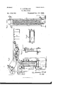
- Figure l is a side view of the machine.
- Fig. 2' is a plan view thereof'.
- Fig. 3 is a vertical central section of the drying apparatus.
- Fig. 4 is a central vertical section of the cooling-cylinder.
- Fig. 5 is a similar section of the absorption-vase.
- Fig. 6 is a like section of the freezer.
- the letter A designates a gas-generator or boiler, into which aqua-ammonia is introduced.
- a safety-valve, a prevents liability of explosion of the boiler.
- ⁇ or near the center of the boiler is a water-glass
- the boiler is half-filled with the required liquid.
- ammonia-gas is evolved, which passes through the tube l 2 into the drier B.
- This drier is preferablyT con-
- the bottom of the drier is convex, so that any moisture which has come over with the gas through the tube 1 2 iiows to the side of the drier and is carried by the tube 25 26 back into the boiler.
- About the tube 2 are attached plates of tin or metal E, and the gas, on Howing up past these plates, is cooled, and any remaining moisture is deposited on the plates E.
- the gas then passes through the tube 3 4 into the worm-tube d din the cooling-cylinder C, through which cylinder C cold water flows continually, entering through the tube 23 and lowin g out through tube 24. From the wormtube d the gas flows through the tube 5 6 into the receiver D, where it is stored up and liquefied b v the pressure generated. On opening thevalve R in the tube 7 8 the gas iiows into the freezer E, constructed as shown in Fig. 6.
- A' represents a tank, preferably of tin or metal, and intended to be filled with water which is to be frozen.
- a flat box, D of similar material, and preferably provided With a flaring bottom.
- a wooden casing surrounds the whole, keeping out atmospheric influences.
- a tube, B', attached to the tank Al regulates the level of water in the same so that its surface just touches the bottom of the box D.
- the tube S is connectedto the tube 20, and when the valve R is opened and the valve S closed the liquid ammonia iiows into the box D', where, on suddenly being released from pressure, it rapidly expands into gas, thereby absorbing the warmth of the box Dl and reducin g its temperature, so that the water in A' is frozen by its contact therewith. As is seen, the water in A freezes from above downward.
- the tube 10 enters the middle compartment through the upper plate, G, and conveys the gas into the same, where it is cooled.
- the liquid in the boiler A which has been deprived of its gas, and consequently' acquired greater specific gravity, sinks to the bottom, and is caused to iiow, by the action of the pump G", through the tube 1l 12, through the coil c c in the cooler G, and through the tube 13 14 into the middle compartment of the absorption-vase F.
- the pump G through the tube 1l 12, through the coil c c in the cooler G, and through the tube 13 14 into the middle compartment of the absorption-vase F.
- the box D In order to take the cake of ice out oi' the tank A', the box D must be raised or swung up on the tubes S 9. In order to free it from the ice-cake in A', the upper surface of which adheres to the bottom ofthe box D, the valveR is closed and the valve S opened, when the warm gas from the boiler A iows through the tube 19 20, through the box D', thawing it free from the upper face of the ice-cake. The box D can now be raised, the tank A lifted out, or the cake of ice therein removed, and on -lling the tank anew the operation may be rcpeated.
- a three-way cock, T, at the junction of the tubes 1 and 19 may be provided for greater security.
- Pressure-gages may be provided to show the amount of compression.
- the absorption-vase F is provided with a tube, 7L, dipping under water in the vessel H, so that the pressure will not become too powerful for the apparatus.
- Any suitable valve operated by the lever a may be provided at 'the lower end of the tube h.
Landscapes
- Engineering & Computer Science (AREA)
- Physics & Mathematics (AREA)
- Mechanical Engineering (AREA)
- Thermal Sciences (AREA)
- General Engineering & Computer Science (AREA)
- Drying Of Solid Materials (AREA)
Description
(No Model.) 2 Sheets-Sheet 1-.
F.' LITTMANN. Ice Machine- No. 234,792. Patented Nov. 23,1880.
N. PETERS. Pnoo-LITHUGRAPMEH. WSHINGTDN- Dl C- No. 234,792. Patented Nov. 23, 1880.
O Ir' @mayb structed as shown in detail in Fig. 3.
UNITED STATES PATENT OFFICE.
FRANZ LITTMANN, OF HALLE-ON-THE-SAALE, PRUSSIA, GERMANY.
ICE-MACHINE.
SPECIFICATION forming part of Letters Patent No. 234,792, dated November 23, 1880.
Application filed April 14, 1880. (No model.)
To all 'whom it may concern:
Be it known that I, FRANZ LITTMANN, a subject of the King of Prussia, residing at Halle-on-the-Saale, Prussia, German Empire, have invented new and useful Improvements in Ice-Machines, of which the following is a specification.
This invention relates to an improvement in ice-machines; and it consists in the combination of a gas-generator, a drying-cylinder, a cooling-cylinder, a receiver, and a freezer, all constructed and arranged as hereinafter set forth. An absorption-vase may also be provided.
The invention also relates to a novel construction of the drying-cylinder, the freezer, and the absorption-vase, hereinafter described.
This invention is illustrated in the accompanying drawings, in which Figure l is a side view of the machine. Fig. 2'is a plan view thereof'. Fig. 3 is a vertical central section of the drying apparatus. Fig. 4 is a central vertical section of the cooling-cylinder. Fig. 5 is a similar section of the absorption-vase. Fig. 6 is a like section of the freezer.
Similar letters indicate corresponding parts.
In these drawings, the letter A designates a gas-generator or boiler, into which aqua-ammonia is introduced. A safety-valve, a, prevents liability of explosion of the boiler. At
`or near the center of the boiler is a water-glass,
b, and the boiler is half-filled with the required liquid. On heating the boiler ammonia-gas is evolved, which passes through the tube l 2 into the drier B. This drieris preferablyT con- The bottom of the drier is convex, so that any moisture which has come over with the gas through the tube 1 2 iiows to the side of the drier and is carried by the tube 25 26 back into the boiler. About the tube 2 are attached plates of tin or metal E, and the gas, on Howing up past these plates, is cooled, and any remaining moisture is deposited on the plates E. The gas then passes through the tube 3 4 into the worm-tube d din the cooling-cylinder C, through which cylinder C cold water flows continually, entering through the tube 23 and lowin g out through tube 24. From the wormtube d the gas flows through the tube 5 6 into the receiver D, where it is stored up and liquefied b v the pressure generated. On opening thevalve R in the tube 7 8 the gas iiows into the freezer E, constructed as shown in Fig. 6.
A' represents a tank, preferably of tin or metal, and intended to be filled with water which is to be frozen. Over the top of the tank A sits a flat box, D, of similar material, and preferably provided With a flaring bottom. The tubes 8 9, which lead into and from this box D', form also hinges for the same, on which it can be swung up by the arms G. A wooden casing surrounds the whole, keeping out atmospheric influences. A tube, B', attached to the tank Al ,regulates the level of water in the same so that its surface just touches the bottom of the box D.
The tube S is connectedto the tube 20, and when the valve R is opened and the valve S closed the liquid ammonia iiows into the box D', where, on suddenly being released from pressure, it rapidly expands into gas, thereby absorbing the warmth of the box Dl and reducin g its temperature, so that the water in A' is frozen by its contact therewith. As is seen, the water in A freezes from above downward.
' On performing its Work the gas flows out through thetube 9 10, and, in order to be again utilized, an absorption-vase, F, is provided. (Fig. 5.) The upper and lower ends ofthe vase are of somewhat larger diameter, so as to form shoulders, against which sit perforated plates G. Through the perforations are passed the ends of the tubes j'f,-which are provided with screw-threads for the accommodation of nuts, which, when tightly screwed into place, cause the plates G to sit air-tight against the shoulders of the vase, producing three compartments therein. Through the tube 21 cold water flows into the vase, through the tubes f, and out through the tube 22, connecting with the tube 23. The tube 10 enters the middle compartment through the upper plate, G, and conveys the gas into the same, where it is cooled. At the same time the liquid in the boiler A, which has been deprived of its gas, and consequently' acquired greater specific gravity, sinks to the bottom, and is caused to iiow, by the action of the pump G", through the tube 1l 12, through the coil c c in the cooler G, and through the tube 13 14 into the middle compartment of the absorption-vase F. Here it is mingled with the IOO gas from the tube 10, and the mixture flows through the tube 15 16 to the pump G", which forces it, through the tube 17 18, back into the boiler A.
In order to take the cake of ice out oi' the tank A', the box D must be raised or swung up on the tubes S 9. In order to free it from the ice-cake in A', the upper surface of which adheres to the bottom ofthe box D, the valveR is closed and the valve S opened, when the warm gas from the boiler A iows through the tube 19 20, through the box D', thawing it free from the upper face of the ice-cake. The box D can now be raised, the tank A lifted out, or the cake of ice therein removed, and on -lling the tank anew the operation may be rcpeated.
A three-way cock, T, at the junction of the tubes 1 and 19 may be provided for greater security.
Pressure-gages may be provided to show the amount of compression. In order to regulate the pressure, also, the absorption-vase F is provided with a tube, 7L, dipping under water in the vessel H, so that the pressure will not become too powerful for the apparatus. Any suitable valve operated by the lever a may be provided at 'the lower end of the tube h.
In former ,ice-machines of this kind the drying apparatusB was omitted, and consequently the moisture in the gas rendered the operation less reliable and more cumbersome, since such moisture is liable to congeal in the tubes and clog the same. By my construction of freezer, also, the use of uncongealable liquid, such as is used in the Pictet ice-machine, as also the mechanism for circulating the same, is rendered unnecessary, thus saving expense.
In conclusion, it may be observed that the difference between the apparatus claimed by me and Patent No. 131,783 will be apparent from an inspection of my claim in connection with said patent.
What I claim as new, and desire to secure by Letters Patent, is-
The combination, in an ice-machine, of the gasgenerator A with the drying-cylinder B, cooling-cylinder G, a receiver, D, a freezer, E, and an absorption-vase, F, with perforated plates G and tubes f, for receiving the utilized vapors, said vase receiving the utilized liquid from the generator, which is then conveyed back to the generator, substantially .as described.
In testimony whereofI haw'e hereunto set my hand and seal in the presence of two subscribing witnesses.
FRANZ LITTMANN.
Publications (1)
| Publication Number | Publication Date |
|---|---|
| US234792A true US234792A (en) | 1880-11-23 |
Family
ID=2304156
Family Applications (1)
| Application Number | Title | Priority Date | Filing Date |
|---|---|---|---|
| US234792D Expired - Lifetime US234792A (en) | littmann |
Country Status (1)
| Country | Link |
|---|---|
| US (1) | US234792A (en) |
-
0
- US US234792D patent/US234792A/en not_active Expired - Lifetime
Similar Documents
| Publication | Publication Date | Title |
|---|---|---|
| US1533336A (en) | Refrigerating apparatus | |
| US234792A (en) | littmann | |
| US236471A (en) | Franz windhausen | |
| US337716A (en) | Apparatus for treating essential oils | |
| US489387A (en) | John a | |
| US63413A (en) | Improved mode of manufacturing ioe | |
| US1512623A (en) | Refrigerating apparatus | |
| US2027382A (en) | Portable dry ice refrigeration | |
| US284515A (en) | Half to moses schwaetz | |
| USRE10261E (en) | stockman | |
| US502437A (en) | Refrigerating apparatus | |
| US2677254A (en) | Liquid cooler and dispenser | |
| US427765A (en) | Ice-machine and method of operating same | |
| US671810A (en) | Ammonia-still. | |
| US220420A (en) | Improvement in ice-making apparatus | |
| US275367A (en) | John c | |
| US502438A (en) | Apparatus for producing cold and ice | |
| US220795A (en) | Improvement in aerators and refrigerators for beer and other liquids | |
| US112654A (en) | Improvement in apparatus for making ice and for refrigerating purposes | |
| US473157A (en) | Daniel l | |
| US177845A (en) | Improvement in ice-machines | |
| US553681A (en) | Charles a | |
| US410244A (en) | Apparatus for distilling anhydrous ammonia | |
| US1225574A (en) | Apparatus for condensing gas under high pressure. | |
| US252021A (en) | davis |