US2343383A - Means and method of balancing propellers - Google Patents
Means and method of balancing propellers Download PDFInfo
- Publication number
- US2343383A US2343383A US388104A US38810441A US2343383A US 2343383 A US2343383 A US 2343383A US 388104 A US388104 A US 388104A US 38810441 A US38810441 A US 38810441A US 2343383 A US2343383 A US 2343383A
- Authority
- US
- United States
- Prior art keywords
- propeller
- unbalance
- aerodynamic
- blade
- blades
- Prior art date
- Legal status (The legal status is an assumption and is not a legal conclusion. Google has not performed a legal analysis and makes no representation as to the accuracy of the status listed.)
- Expired - Lifetime
Links
- 238000000034 method Methods 0.000 title description 19
- 230000000694 effects Effects 0.000 description 34
- 238000012937 correction Methods 0.000 description 17
- 238000005259 measurement Methods 0.000 description 11
- 239000012530 fluid Substances 0.000 description 6
- 239000007788 liquid Substances 0.000 description 4
- 230000000737 periodic effect Effects 0.000 description 4
- 230000007547 defect Effects 0.000 description 3
- 230000003068 static effect Effects 0.000 description 3
- 150000001875 compounds Chemical class 0.000 description 2
- 230000013707 sensory perception of sound Effects 0.000 description 2
- 230000001360 synchronised effect Effects 0.000 description 2
- 230000001131 transforming effect Effects 0.000 description 2
- 241000219498 Alnus glutinosa Species 0.000 description 1
- 238000006679 Martin dehydration reaction Methods 0.000 description 1
- 230000000052 comparative effect Effects 0.000 description 1
- 230000008878 coupling Effects 0.000 description 1
- 238000010168 coupling process Methods 0.000 description 1
- 238000005859 coupling reaction Methods 0.000 description 1
Images


Classifications
-
- G—PHYSICS
- G01—MEASURING; TESTING
- G01M—TESTING STATIC OR DYNAMIC BALANCE OF MACHINES OR STRUCTURES; TESTING OF STRUCTURES OR APPARATUS, NOT OTHERWISE PROVIDED FOR
- G01M1/00—Testing static or dynamic balance of machines or structures
- G01M1/14—Determining imbalance
- G01M1/16—Determining imbalance by oscillating or rotating the body to be tested
- G01M1/22—Determining imbalance by oscillating or rotating the body to be tested and converting vibrations due to imbalance into electric variables
-
- Y—GENERAL TAGGING OF NEW TECHNOLOGICAL DEVELOPMENTS; GENERAL TAGGING OF CROSS-SECTIONAL TECHNOLOGIES SPANNING OVER SEVERAL SECTIONS OF THE IPC; TECHNICAL SUBJECTS COVERED BY FORMER USPC CROSS-REFERENCE ART COLLECTIONS [XRACs] AND DIGESTS
- Y10—TECHNICAL SUBJECTS COVERED BY FORMER USPC
- Y10S—TECHNICAL SUBJECTS COVERED BY FORMER USPC CROSS-REFERENCE ART COLLECTIONS [XRACs] AND DIGESTS
- Y10S29/00—Metal working
- Y10S29/901—Balancing method
-
- Y—GENERAL TAGGING OF NEW TECHNOLOGICAL DEVELOPMENTS; GENERAL TAGGING OF CROSS-SECTIONAL TECHNOLOGIES SPANNING OVER SEVERAL SECTIONS OF THE IPC; TECHNICAL SUBJECTS COVERED BY FORMER USPC CROSS-REFERENCE ART COLLECTIONS [XRACs] AND DIGESTS
- Y10—TECHNICAL SUBJECTS COVERED BY FORMER USPC
- Y10T—TECHNICAL SUBJECTS COVERED BY FORMER US CLASSIFICATION
- Y10T29/00—Metal working
- Y10T29/49—Method of mechanical manufacture
- Y10T29/49316—Impeller making
- Y10T29/49332—Propeller making
Definitions
- This invention relates to an improved method and apparatus for balancing aeronautical propellers and has particular reference to an improved method and apparatus for separately determining aerodynamic or, dynamic unbalance in such a propeller.
- An object of the invention resides in the provision of an improved method and apparatus for completely balancing an aeronautical propeller by separating the effect of aerodynamic unbalance from the efiect of mass unbalance so that both of these vibration creating defects can be determined both as to location and magnitude and eliminated from the propeller.
- a further object resides in the provision of a simple and eifective apparatus for detecting the location and magnitude of aerodynamic unbalance and in an aeronautical propeller so that this factor of propeller unbalance can be eliminated before attempting to correct an out of balance condition of the propeller mass.
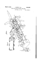
- Fig. 1 is a schematic side-elevational view of a propeller aerodynamic unbalance detecting device constructed according to the invention.
- Fig. 2 is a side view of a fragmentary portion of the detecting device.
- Fig. 3 is a front elevational view of a portion of the device illustrated in Fig. 2.
- Fig. 4 is a fragmentary sectional view of the device taken on the line l-lof Fig. 3.
- Fig. 5 is a perspective view of the propeller supporting and driving mechanism showing the devices for detecting dynamic unbalance of the propeller.
- Fig. 6 is a schematic view of the electrical circuits of a propeller balancing machine for indieating the magnitude and angular position of vibrational eifects caused by mass and aerodynamic unbalance of the propeller, and
- Fig. 7 is a schematic illustration of a somewhat modified form of propeller aerodynamic unbalance detecting device.
- the aerodynamic forces acting on the several blades produce a thrust moment on each blade acting about an axis substantially perpendicular to the axis of rotation of the propeller and to the longitudinal axis of the blade. Because of slight variations in angle of attack or slight difierences in the aerodynamic shape of the several blades one blade may produce a slightly greater or slightly lesser moment than the remaining blade or blades. This condition also gives the propeller a tendency to wobble when in operation.
- the numeral ll generally indicates an aeronautical propeller which may be ofsome form well known to the art.
- the propeller illustrated has a hub portion I! carrying three blades I, II and ll as indicated in Fig. 3.
- the propeller II is mounted on one end of a shaft ll driven by a motor 22.
- the motor is supported on a machine base 24 a portion 2! of which carries a cylindrical extension 28 through which the shaft 2. extends and within which are disposed suitable bearings for supporting the drive shaft, as particularly illustrated in Fig. and hereinafter described in detail.
- a substantially circular disc member ll preferably formed of sections of wire mesh screen mounted on a supporting framework 32 which may conveniently be formed of welded lengths of light gauge tubing.
- the screen disc 30 may conveniently be formed of a plurality of sections, as indicated at Ila, Ilb.
- the disc member including the screen II and frame I2, is supported independently of the shaft '20 and its hearings on vertically aligned pivotal mountings 34 and ll carried at the ends of respective arms 38 and ll secured to a ring 42 which surrounds the cylindrical member 2! and is mounted on the cylindrical member or on suitable supports. as indicated at 44, extending from the machine base portion II.
- This disc member is preferably so constructed as to have a natural frequency of vibratory movement above the principal vibration frequencies of the propeller when rotating at balancing speeds. This is desirable to avoid a condition of resonance between the natural frequency of the discstructure and the principal aerodynamic disturbances which condition might produce distortions in the disc and lead to inaccuracies in the measurement of the aerodynamic unbalance.
- pivotal mountings While various forms of pivotal mountings might be used. it has been found convenient to form these mountings of two opposed blocks, as indicated at 48 and 48 for the block 30, having double beveled adjacent faces and secured together by leaf springs, as indicated at 80 and H, which cross each other between the blocks which they secure together.
- the mounting II is identical with the mounting 3i.
- the ring 42 also carries a pair of arms I and an electrical pick-up device. as indicated at 82 and Il, and each pick-up device has a connection with the frame 32 as indicated at 88 and 6?.
- Each electrical pick-up device may comprisr a permanent magnet ll carried on the end of the respective arm 5' or 80, and a light weight coil, as indicated at 12, connected with the frame 32 to move therewith.
- Fig. 5 is a perspective view of the driving and supporting means for the propeller shaft 20, it will be observed that the shaft is supported by two cantilever beams 45 and 43 in two bearings as indicated at 18 and 80 and driven by the motor 22.
- the bearing 80 is supported by suitable flexible means, such as the cables 82 and 84 extending downwardly from fixed supports such as the arms 86 and 88 mounted on the cantilever beams 45 and 43 and the bear mg I. is supported by similar cables 90 and 52 extending upwardly from suitable fixed supports such as the arms 94 and 98.
- This support together with the above-described support for screen II insulates the screen from vibrations of the shaft 2
- Each of the bearings 18 and 80 carries a lateral projection, as indicated at I08 and 0, respectively, the outer ends of which actuate electric pick-up devices, as indicated respectively at H2 and I ll. each of these pick-ups comprising a permanent magnet and a movable coil as indicated above for the pick-ups connected with the pivoted diaphragm Ill.
- each of the horizontal arms II and II carries at its outer end With this arrangement lateral movements of the shaft 2
- the propeller is mounted on the end of the shaft 20 adjacent to the screen II and is rotated by the motor 22 at a speed at which aerodynamic unbalance of the propeller blades will produce a definite effect on the propeller wake. Ithas been found experimentally that a propeller speed of approximately six hundred revolutions per minute is sufficient to produce these effects, but it may be found desirable to rotate the propeller at speeds nearer the usual propeller operating speeds if it should become necessary to obtain more exact measurement in practice.
- the switches I I8 and I20 will be positioned to connect the leads I22 and I24 from the respective pick-ups 62 and 64 with the electrical system or the machine.
- This electrical system includes a compensating generator I26, a measuring generator I28, potentiometers I30, I32 and I34, an amplifying device I36 and a wattmeter I38.
- the compensating generator I26 has four stator field coils I40, I42, I44 and I46 disposed ninety degrees apart and mounted in a fixed support and an armature I41 comprising a permanent magnet fixed on the shaft 20. Each of these coils is connected in series with a variable resistance or potentiometer as indicated at I48, I50, I52 and- I54, respectively.
- Coil I40 is connected with one switch point C and coil I 46 is connected with another switch point C through which they may be connected with one side of a pick-up.
- Coil I42 is connected with one switch point C1 and coil I 44 is connected to another switch point C1 through which they may be connected through various mechanism with the other side of the pick-up.
- switches I68 and I10 are on switch points C1 coils I42 and I44 are connected in series by connection I55.
- the measuring generator I28 has two field or stator coils I56 and I58 and a permanent magnet armature I63 fixed on the shaft 20.
- the coils I56 and I58 are spaced ninety degrees apart and are mounted on a rotatable support I12 so that their position relative to the fixed support and to the fixed coils of the compensating generator may be ,changed at will.
- coil I56 is called the zero degree coil and I58 the ninety degree coil.
- the wattmeter has a current coil I60 selectively connectible with either coil I56 or I58 of the measuring generator and a coil I6I connected with the amplifying device I36 of the electrical system.
- a current coil I60 selectively connectible with either coil I56 or I58 of the measuring generator and a coil I6I connected with the amplifying device I36 of the electrical system.
- the compensating generator I26 is connected into the circuit by closing the switches I64, I66, I68 and I with the corresponding calibrating or C contacts.
- the pick-ups 62 and 64 are connected in series so as to assist each other and have their voltages add, although they will always be moving in opposite directions. It might be stated that only one pick-up is essential but the provision of two tends to cancel impulses produced by tions.
- the pick-ups are connected into the system so that the impulses travel from one pick-up through the amplifier, switch I16 being connected with R and switch I14 being connected with L, through the other pick-up, then through the four coils of the compensating generator and hence back to the first pick-up.
- the compensating generator is used solely to electrically balance out any voltage that may be generated by the pick-up 62 and 64 due to any unbalance of the propeller originally selected to start the tests, thus avoiding the necessity of obtaining a perfect- 1y balanced propeller for calibrating the indicating portions of the machine.
- the generator stator setting is the measuring the correction which must be applied to simulate the conditions which would exist if a perfectly balanced propeller has been installed.
- Blade number I4 is now adjusted through a known angle, for example, one degree in increase in pitch. Additional voltages will now be produced by the pick-ups 62 and 64 and will provide a reading on the wattmeter I38. The measuring generator stator I12 will now be rotated until the reading of the wattmeter I38 is returned to zero.
- the measuring generator stator I12 is now rotated one hundred and twenty degrees clockwise as seen in Fig. 3, its position will be that in which the network will not measure the unposition last described positionis position for measuring the unbalance in either blade II or II. Again, since blade II has been selected as the reference blade, this generator the proper one for determining the correction to be applied to blade II. As blade It now has a known uncompensated unbalance aerodynamically. the wattmeter will show a reading. With the generator in this last mentioned position, the variable resistance or potentiometer IN is adjusted so that the wattmeter I38 indicates the angle in degrees through which the blade II was arbitrarily changed, that is, one degree for the illustration given above.
- the movable held or stator ill of the measuring generator III is moved to its zero degree angu ar position so that the zero degree coil I58 of this generator and the zero degree coil Ill of the compensating generator I28 will produce a current and a voltage, respectively, exactly in phase with each other.
- the switches II! and I2! being in contact with the points marked D on Fig. 6 of the accompanying drawings, when the propeller II is .rotated, electrical currents from the electrical pick-ups III and I I4 will be fed into the electrical system.
- the switches I64 and I" are on the contacts indicated by C and switches I" and I'll are on the .contacts indicated by Cr in order to connect the compensating generator III into the system so that the voltages produced by this generator will be in series with the voltage generated in the electric pick-ups! and II.
- the potentiometers I30 and It! will be changed so that the movable contacts are brought to the position indicated by a in each case and the switches Ill and I1!
- switch number It! should be moved to connect the ninety degree coil I58 with the wattmeter so that the wattmeter will now measure the remaining components of the voltage generated by the electrical pick-up III.
- the potentiometer I50 across the two hundred and seventy degree coil I42 of the compensating generator is now adjusted to again reduce the wattmcter reading to zero.
- the wattmeter should now be made to read zero by adjusting the potentiometer I30 which will in eflect utilize some of the voltage induced by pickup III to oppose the voltage of pick-up I I4. Under these conditions the zero wattmeter reading indicates that a sullicient portion of the output of the pick-up H2, which is in electrical opposition with the pick-up II4, has been combined with the latter to nullify it completely. Thus, there will be no indication in pick-up H4 of unbalance in the plane of weight I18.
- wattmeter will now indicate unbalance in the plane of weight I 88 caused by unbalance weight I88.
- variable potentiometer I34 the wattmeter reading may be changed or calibrated to read this known unbalance in this known plane in any desired unit.
- the balance disturbing weights I18 and I88 may be conveniently mounted on the propeller by providing balanced rings surrounding the propeller hub at each side of the blade supporting portion or the hub and securing suitable weights to these rings.
- Similar nulliiication and calibration operations may be carried out for unbalance in the plane of weight I18 by moving switches I14 and I18 to the L position and adjusting the potentiometer I82 to give a zero indication on the wattmeter of the unbalance produced by weight I88.
- the unbalance weight I88 is now removed from the propeller and the unbalance weight I18 01' known value is again put in position on the propeller and the potentiometer I84 adjusted to cause the wattmeter I38 to read this known unbalance in a desired correction unit.
- the propeller With the completion of the indicated correction for mass unbalance and with the aerodynamic unbalance already having been corrected by promptly setting the blades to the correct pitch angle, the propeller will and mass balance.
- the propeller In the arrangement illustrated in Fig. 7 the propeller is mounted on a shaft 28 driven by a motor 22 in the manner indicated above and the motor and shaft may be supported on machine base portions such as indicated at 24 and 28 in Fig. 1 if desired.
- I82c, I82d and I82e are arranged along a radiant extending outwardly from the axis of rotation of the propeller I8 and may be spaced along this radiant as may be round convenient or desirable for obtaining the most desirable indication of the aerodynamic eilect produced in the wake of the propeller blades. All of these Pitot tubes lead into a pressure chamber I84 to one end or which is connected a rotatable valve I 88 which is rotated in synchronism with the propeller by suitable means, such as the drive shaft I88 operatively connected between the motor 22 and the valve.
- a compound manometer I88 having three legs as indicated at I82a, I821).
- the propeller blades can be adiusted to decrease the diil'erence in the aerodynamic eil'ect produced and a condition of substantially perfect aerodynamic balance will be obtained when the liquid columns all have the same level in the respective legs of the compound manometer. Ii. desired a separate manometer for each blade can be used without in any way exceeding the scope or the invention.
- Apparatus for indicating the angular position with respect to the blades of a multi-blade aerodynamic propeller at which a vibration producing aerodynamic effect is produced when the propeller is rotated at operating speed comprisnow be in aerodynamic ing, means for supporting and rotating the propeller, a diaphragm pivotally supported immediately to the rear of the propeller position, a motion responsive device, including means for producing impulses upon movement of said diaphragm, operatively connected to said diaphragm, and means for correlating the impulses of said motion responsive device with the angular position of the propeller at the time the motion of the diaphragm occurs.
- Apparatus for indicating the angular position with respect to the blades of an aerodynamic propeller at which a vibration producing aerodynamic effect is produced when the propeller is rotated at operating speed comprising, means for supporting and rotating the propeller, a diaphragm pivotally supported immediately to the rear of the propeller position on pivots positioned along a diameter of said diaphragm, a motion responsive device, including means for producing impulses upon movement of said diaphragm, operatively connected to said diaphragm at a location between said pivots and spaced from said diameter, and means for correlating the impulses of said motion responsive device with the angular position of the propeller at the time the motion of the diaphragmoccurs.
- Apparatus for indicating the angular position with respect to the blades of an aerodynamic propeller at which a vibration producing aerodynamic effect is produced when the propeller is rotated at operating speed comprising, means for supporting and rotating the propeller, a diaphragm pivotally supported immediately to the rear of the propeller position on pivots positioned along a diameter of said diaphragm, an electric current generating device supported'adjacent to said diaphragm at a position between said pivots and spaced from said diameter and operatively connected with said diaphragm, and means for comparing the current signals from said generating device with current signals from a different generating device the signal strength and timing of the signals of which relative to the rotational position of the propeller is known.
- Apparatus for indicating which one of the several blades of a multi-blade propeller produces a balance disturbing aerodynamic effect comprising, a Pitot tube mounted immediately behind the propeller position and in the propeller wake with its open end directed into the airflow from said propeller, a plurality of manometer tube legs, one for each propeller blade, and a valve driven in synchronism with the propeller for connecting said manometer legs seriatim with said Pitot tube as the corresponding propeller blades pass the open end of said tube.
- 5,-Apparatus for indicating which one of the several blades of a multi-blade propeller produces a balance disturbing aerodynamic eifect comprising, a plurality of Pitot tubes mounted immediately behind the propeller position with their open ends directed into the airflow from the propeller and distributed within an area substantially the same as the face area of a propeller blade, a plurality of manometer tube legs one for each propeller blade, a chamber connected with all of said Pitot tubes, and a valve driven in synchronism with the propeller for connecting said manometer legs seriatim with said chamber as the corresponding propeller blades pass the open ends of said manometer tubes.
- a propeller balancing method which comprises, rotating the propeiler on a fixed mount at assasas a speed sumcient to produce in the propeller wake aerodynamic disturbances characteristic of aerodynamic unbalance of the propeller, measuring the magnitude of only such disturbances in a region spaced from said propeller and in a selected portion of the propeller disc, timing said measurements with the passage of the various propeller blades through said selected disc portion, and correcting the aerodynamic unbalance by adjusting the propeller blade in accordance with said timed measurements.
- Apparatus for detecting and indicating thrust unbalance in a fluid displacing rotor comprising, means for supporting said rotor and rotating it at a speed sufllcient for the rotor blades to produce a definite fluid movement in the wake of the rotor, and means, located in said rotor wake and spaced from said rotor, transforming at least a portion of the fluid movement in said wake into fluid pressure proportional to said fluid movement, means energized by the eilect of said fluid pressure for indicating thrust effects produced by the several rotor blades including means correlating the aerodynamic effect indications in the rotor wake with corresponding blades.
- Apparatus for detecting and indicating aerodynamic unbalance in a multi-blade aeronautical propeller comprising, mechanism for supporting said propeller and rotating it with respect to said detecting apparatus at a speed suflicient for the propeller blades to produce a deflnite air movement in the wake of the propeller, means located in said propeller wake energized by impingement of the air in the wake of said propeller on said means, adevice operatively connected with said means for indicating diflerences in the air movement in the propeller wake effected by the several propeller blades, and means for correlating said differences with the corresponding blades.
- Apparatus for indicating which of the several blades of a multi-blade propeller produces a balance disturbing aerodynamic effect comprising, means for supporting said propeller and means for rotating said propeller, non-rotatable detecting means independent of said first mentioned means and movement thereof and spaced from, and disposed immediately to the rear of, the propeller and energized by propeller slip stream air impinging thereon for detecting said balance disturbing aerodynamic eflect, means actuated by said detecting means for indicating the disturbing aerodynamic effects and means synchronized with the rotation of said propeller and operatively associated with said indicating means for indicating the propeller blade or blades creating said effect.
- Apparatus for indicating the angular position with respect to the blades of a multi-blade propeller at which a vibration producing aerodynamic eifect is produced when the propeller is rotated at operating speed comprising, means including a shaft and bearings for supporting and rotating the propeller, non-rotatable airflow responsive detecting means supported independently of said shaft and bearings and positioned immediately to the rear of the propeller position and energized by propeller slip stream air impinging thereon for detecting said vibration producing aerodynamic effect, means actuated by said detecting means for indicating said effect, and means synchronized with the rotation of the propeller and operatively associated with said detecting means for indicating the angular position with respect to the propeller blades at which said effect occurs.
- Means for detecting. locating and measuring aerodynamic unbalance in a propeller mounted on a rotating drive shaft comprising, means mounted independently of said propeller and drive shaft for transforming air velocity in an airstream into air pressure and utilizing that air pressure for individually measuring the relative energy imparted to the air stream by each rotating propeller blade as it passes a given point, including means for indicating which bla'de imparted the measured energy and the quantity of that energy relative to the energy imparted by another blade.
- Means for determining propeller aerodynamic unbalance by individually observing the efiect produced upon an air stream by each blade of a rotating propeller comprising, a device, with respect to which the propeller rotates, spaced from said propeller and located in the air stream produced by the propeller, said device including, means energized by air in said airs'tream impinging thereon, by absorbing at least a portion of the energy in said air stream, and connected with indicating means for indicating the effect of said air stream on said means and hence the efiect of the propeller blades on the air stream, means for correlating such indications to particular blades, and means for indicating the quantity of the effect on the air stream produced by each blade.
- a device located in the propeller slipstream and movable by air of said slipstream, having periodic variations in velocity, impinging thereon, means for detecting the movement of said device, and means for connecting said detecting means with said mechanism for utilizing said mechanism for locating the position with respect to said propeller blades and the quantity of said periodic variations to thereby determine the correction to be applied to each blade to produce a propeller slipstream without periodic variations.
- the method of determining and correcting the aerodynamic unbalance of a propeller having a plurality of blades which comprises, rotating the propeller at a'speed sufiicient to produce characteristic aerodynamic disturbances in the propeller slipstream, selecting a blade as a reference blade, determining the difierences between the effect produced on an object by impingement on said object of the slipstream created by said reference blade and the respective effects produced on said object by the slipstream created by each blade other than the reference blade by measuring the eiiect of said slipstream on said object and timing said measurements with the rotation of said propeller and adjusting each blade other than the reference blade in accordance with said differences so as to make the effects all the same.
- the method of completely balancing an aeronautical propeller having a plurality of blades by correcting both dynamic and aerodynamic unbalance comprises, first supporting and rotating said propeller, measuring the effect of variations in the slipstream of the rotating propeller by measuring in timed relation with the rotation of said propeller the effect of impingement of said slipstream on an object for determining the aerodynamic unbalance between the respective blades of said propeller without regard to the dynamic unbalance, eliminating said aerodynamic unbalance and again rotating said propeller and with the aerodynamic defects eliminated determining the dynamic unbalance,'and then eliminating said dynamic unbalance.
- the method of determining aerodynamic unbalance of the blades of a propeller which is rotating at a speed suillcient to produce characteristic aerodynamic disturbances in the propeller wake comprises, measuring the eil'ects produced by air in said wake, energized by certain blades, impinging on an obstruction located in said wake, and timing said measurementswith the rotation of said propeller.
- the method of detrmining aerodynamic unbalance caused by a blade of a multi-bladed propeller which comprises rotating said propeller in front of an obstruction at a speed sufilcient to produce characteristic aerodynamic disturbances in the propeller wake, measuring the effects on said obstruction of variations in air current im-" pinging thereon, selecting a blade as a reference blade and timing said measurements with respect. to said rotating propeller so that the difierence between the effects of one blade and the eflect of said reference blade are observed, which difference will be a measure of the aerodynamic unbalance of said one blade.
- Apparatus for indicatin the aerodynamic unbalance of a three bladed propeller comprisin, means for gupportina and rotating said propeller, means. mounted independent oi said supporting means, for measuring variations in the l velocity of the slipstream of said propeller,
Landscapes
- Physics & Mathematics (AREA)
- General Physics & Mathematics (AREA)
- Testing Of Balance (AREA)
Description
March 7, 1944. E. MARTIN ETAL 2,343,383-
MEANS AND METHOD OF BALANCING PROPELLERS Filed April 11, 1941- 4 Sheets-Sheet 1 [90 INVENTORS ERLE MART/N MURRA Y CIBEEBE JR. B am 4. M
ATTORNEY March 7, 1944. E.-MART|N EIAL V 2,343,383
MEANS AND METHOD OF BALANCING PROPELLERS Filed Aprilwll 1941 4 Sheets-Sheet 2 INVENTORS EQLE MAR TIN W MURRAYCBEEBEJR. N M 4. m
N ATTORNEY March 7, 1944.
E. MARTIN ETAL 2,343,383
MEANS AND METHOD OF BALANCING PROPELLERS Filed April 11, 1941 4 Sheets-Sheet 3 INVENTORS EQLE MART/N MURRAY C 55555 JR.
. ATTORNEY March 7, 1944. w E. MARTIN EI'AL MEANS AND METHOD OF BALANCING PROPELLERS 4 Sheets-Sheet 4 Filed April 11, 1941 J w mrm w. R MN 3 w W m n 1mm A f Patented Mai- 7, 1944 MEANS AND METHOD OF BALANCING PROPELLERS Erie Martin, West Hart Beebe, Jr., Glastonbur United Aircraft i'ord, and Murray C.
, Conn., assignors to Corporation, East Hartford,
Conn., a corporation of Delaware Application April 11, 1941, Serial No. 388,104
21 Claims.
This invention relates to an improved method and apparatus for balancing aeronautical propellers and has particular reference to an improved method and apparatus for separately determining aerodynamic or, dynamic unbalance in such a propeller.
An object of the invention resides in the provision of an improved method and apparatus for completely balancing an aeronautical propeller by separating the effect of aerodynamic unbalance from the efiect of mass unbalance so that both of these vibration creating defects can be determined both as to location and magnitude and eliminated from the propeller.
A further object resides in the provision of a simple and eifective apparatus for detecting the location and magnitude of aerodynamic unbalance and in an aeronautical propeller so that this factor of propeller unbalance can be eliminated before attempting to correct an out of balance condition of the propeller mass.
Other objects and advantages will be more particularly pointed out hereinafter or will become apparent as the description proceeds.
In the accompanying drawings, in which like reference numerals are used to designate similar parts throughout, there is illustrated a suitable constructional form of dynamic and aerodynamic unbalance determining apparatus for the purpose of disclosing the invention, and a some 118.15 modified form of apparatus for determining the location and magnitude of aerodynamic unbalance. The drawings, however, are for the purpose of illustration only and are not to be taken as limiting or restricting the invention since it will be apparent to those skilled in the art that various changes in the illustrated constructional forms may be resorted to without in any way exceeding the'scope of the invention.
In the drawings,
Fig. 1 is a schematic side-elevational view of a propeller aerodynamic unbalance detecting device constructed according to the invention.
Fig. 2 is a side view of a fragmentary portion of the detecting device.
Fig. 3 is a front elevational view of a portion of the device illustrated in Fig. 2.
Fig. 4 is a fragmentary sectional view of the device taken on the line l-lof Fig. 3.
Fig. 5 is a perspective view of the propeller supporting and driving mechanism showing the devices for detecting dynamic unbalance of the propeller.
Fig. 6 is a schematic view of the electrical circuits of a propeller balancing machine for indieating the magnitude and angular position of vibrational eifects caused by mass and aerodynamic unbalance of the propeller, and
Fig. 7 is a schematic illustration of a somewhat modified form of propeller aerodynamic unbalance detecting device.
of unbalance .which will produce undesirable 1 vibrations-during propeller operation. One of these is the condition in which the mass of the propeller is not symmetrically distributed about the axis of propeller rotation producing dynamic and/or static unbalance which condition will cause vibration of the propeller during operation. Dynamic vibration usually being caused by force couples which tend to cause the propeller disc to wobble about some point along the axis of propeller rotation and static unbalance being caused by a radial force which tends to cause the propellerdisc to move radially. The other important condition is that of unequal aerodynamic effectiveness of the different propeller blades. In operation the aerodynamic forces acting on the several blades produce a thrust moment on each blade acting about an axis substantially perpendicular to the axis of rotation of the propeller and to the longitudinal axis of the blade. Because of slight variations in angle of attack or slight difierences in the aerodynamic shape of the several blades one blade may produce a slightly greater or slightly lesser moment than the remaining blade or blades. This condition also gives the propeller a tendency to wobble when in operation.
When it is attempted to finally balance a propeller after assembly both of the above described conditions combine to produce vibrational eifects and it is not usually possible to determine from a general vibrational analysis just what part of the total vibration is due to mass unbalance and what part is due to aerodynamic unbalance. It, therefore, becomes ex-' ceedingly diflicult if not impossible to completely correct the mass unbalance of the propeller without separately determining the angular location and magnitude of both the aerodynamic unbalance and the dynamic unbalance. While both mass and aerodynamic unbalance might be corrected by a single adjustment of either the mass distribution or aerodynamic eflects to place the propeller in satisfactory balance for operation at one altitude, the condition of balance thus obtained would-not be effective at different altitudes since the mass effects will remain substantially constant but the aerodynamic effects will vary with changes in altitude. This is given as one example of the reasons for independently correcting defects leading to mass and to aerodynamic imbalance. As stated above, it is among the objects of this invention to produce an effective method and apparatus for determining and eliminating both the aerodynamic unbalance effect and the mass unbalance.
Referring to the accompanying drawings in detail, the numeral ll generally indicates an aeronautical propeller which may be ofsome form well known to the art. The propeller illustrated has a hub portion I! carrying three blades I, II and ll as indicated in Fig. 3.
In order to determine the aerodynamic and mass unbalance including both static and dynamic unbalance the propeller II is mounted on one end of a shaft ll driven by a motor 22. The motor is supported on a machine base 24 a portion 2! of which carries a cylindrical extension 28 through which the shaft 2. extends and within which are disposed suitable bearings for supporting the drive shaft, as particularly illustrated in Fig. and hereinafter described in detail. Surrounding the shaft ll immediately to the rear of the propeller there is a substantially circular disc member ll preferably formed of sections of wire mesh screen mounted on a supporting framework 32 which may conveniently be formed of welded lengths of light gauge tubing. The screen disc 30 may conveniently be formed of a plurality of sections, as indicated at Ila, Ilb. "c, "d, "e, "I, "a and "h, in Fig. 3, secured together along their adjacent edges by rows of tensioning springs, as indictaed at 3|. The disc member, including the screen II and frame I2, is supported independently of the shaft '20 and its hearings on vertically aligned pivotal mountings 34 and ll carried at the ends of respective arms 38 and ll secured to a ring 42 which surrounds the cylindrical member 2! and is mounted on the cylindrical member or on suitable supports. as indicated at 44, extending from the machine base portion II. This disc member is preferably so constructed as to have a natural frequency of vibratory movement above the principal vibration frequencies of the propeller when rotating at balancing speeds. This is desirable to avoid a condition of resonance between the natural frequency of the discstructure and the principal aerodynamic disturbances which condition might produce distortions in the disc and lead to inaccuracies in the measurement of the aerodynamic unbalance.
While various forms of pivotal mountings might be used. it has been found convenient to form these mountings of two opposed blocks, as indicated at 48 and 48 for the block 30, having double beveled adjacent faces and secured together by leaf springs, as indicated at 80 and H, which cross each other between the blocks which they secure together. The mounting II is identical with the mounting 3i.
The ring 42 also carries a pair of arms I and an electrical pick-up device. as indicated at 82 and Il, and each pick-up device has a connection with the frame 32 as indicated at 88 and 6?.
Each electrical pick-up device may comprisr a permanent magnet ll carried on the end of the respective arm 5' or 80, and a light weight coil, as indicated at 12, connected with the frame 32 to move therewith.
Referring now to Fig. 5 which is a perspective view of the driving and supporting means for the propeller shaft 20, it will be observed that the shaft is supported by two cantilever beams 45 and 43 in two bearings as indicated at 18 and 80 and driven by the motor 22. The bearing 80 is supported by suitable flexible means, such as the cables 82 and 84 extending downwardly from fixed supports such as the arms 86 and 88 mounted on the cantilever beams 45 and 43 and the bear mg I. is supported by similar cables 90 and 52 extending upwardly from suitable fixed supports such as the arms 94 and 98. This support together with the above-described support for screen II insulates the screen from vibrations of the shaft 2| and its bearings. The difference in the directions in which the respective bearing supporting cables extend is occasioned by the overhang of the shaft II, the weight of the shaft and the propeller causing a downward force on the bearing 80 and an upward force on the hearing II. The propeller thrust is transmitted through the bearing 18 to the longitudinally extending cables I and Ill connected to their ends to the rings I02 and Hi pivotally secured to the fixed portion of the machine while permitting the bearing to follow the movements of the shaft 20. Flexible couplings llll and I0! providing a limited universal action to provide freedom of movement of the shaft Ill under the influence of propeller unbalance and prevent disturbances incident to motor and motor drive unbalance being transmitted to the shaft, are incorporated between the motor drive shaft and the adjacent end of the shaft 20.
Each of the bearings 18 and 80 carries a lateral projection, as indicated at I08 and 0, respectively, the outer ends of which actuate electric pick-up devices, as indicated respectively at H2 and I ll. each of these pick-ups comprising a permanent magnet and a movable coil as indicated above for the pick-ups connected with the pivoted diaphragm Ill.
ll angularly disposed mid-way between the diametrically opposed arms 3! and ll so that the center lines of the arms 58 and I lie substantially in a horizontal plane. Each of the horizontal arms II and II carries at its outer end With this arrangement lateral movements of the shaft 2| occasioned by vibration of the propeller II can be electrically indicated.
Electrical leads from the pick- ups 62 and 64 and from the pick-ups ill and H4 are carried to an electrical analyzing device generally indicated at ill in Fig. 1 and diagrammatically illustrated in Fig. 6.
p In applying this apparatus to balancing an aeronautical propeller, the propeller is mounted on the end of the shaft 20 adjacent to the screen II and is rotated by the motor 22 at a speed at which aerodynamic unbalance of the propeller blades will produce a definite effect on the propeller wake. Ithas been found experimentally that a propeller speed of approximately six hundred revolutions per minute is sufficient to produce these effects, but it may be found desirable to rotate the propeller at speeds nearer the usual propeller operating speeds if it should become necessary to obtain more exact measurement in practice. With the propeller rotating at some selected speed at which the aerodynamic unbalance of the propeller blade is measurable within the desired degree or accuracy, the switches I I8 and I20 will be positioned to connect the leads I22 and I24 from the respective pick- ups 62 and 64 with the electrical system or the machine. This electrical system includes a compensating generator I26, a measuring generator I28, potentiometers I30, I32 and I34, an amplifying device I36 and a wattmeter I38.
The compensating generator I26 has four stator field coils I40, I42, I44 and I46 disposed ninety degrees apart and mounted in a fixed support and an armature I41 comprising a permanent magnet fixed on the shaft 20. Each of these coils is connected in series with a variable resistance or potentiometer as indicated at I48, I50, I52 and- I54, respectively. I
The coils I40 and I42 arranged at ninety degrees to each other and for convenience called the zero degree and two hundred and seventy degree coils, respectively, are connected in series and coils I44 and I46 called for convenience the v one hundred and eighty degree and ninety degree coils, respectively, are also connected in series. Coil I40 is connected with one switch point C and coil I 46 is connected with another switch point C through which they may be connected with one side of a pick-up. Coil I42 is connected with one switch point C1 and coil I 44 is connected to another switch point C1 through which they may be connected through various mechanism with the other side of the pick-up. When switches I68 and I10 are on switch points C1 coils I42 and I44 are connected in series by connection I55.
- The measuring generator I28 has two field or stator coils I56 and I58 and a permanent magnet armature I63 fixed on the shaft 20. The coils I56 and I58 are spaced ninety degrees apart and are mounted on a rotatable support I12 so that their position relative to the fixed support and to the fixed coils of the compensating generator may be ,changed at will. For convenience coil I56 is called the zero degree coil and I58 the ninety degree coil.
The wattmeter has a current coil I60 selectively connectible with either coil I56 or I58 of the measuring generator and a coil I6I connected with the amplifying device I36 of the electrical system. As is well known, if no voltage is impressed on the voltage coil the wattmeter will show a zero reading even if current is flowing in the current coil, and as the power of an alternating circuit is expressed by El cos 0, where is the phase angle between the voltage E and the current I, the wattmeter will also show a zero reading if the current and voltage impulses are ninety degrees out of phase.
After the pick- ups 62 and 64 have been connected with the electrical circuit by the switches H8 and I20, the compensating generator I26 is connected into the circuit by closing the switches I64, I66, I68 and I with the corresponding calibrating or C contacts. The pick- ups 62 and 64 are connected in series so as to assist each other and have their voltages add, although they will always be moving in opposite directions. It might be stated that only one pick-up is essential but the provision of two tends to cancel impulses produced by tions. The pick-ups are connected into the system so that the impulses travel from one pick-up through the amplifier, switch I16 being connected with R and switch I14 being connected with L, through the other pick-up, then through the four coils of the compensating generator and hence back to the first pick-up. The compensating generator is used solely to electrically balance out any voltage that may be generated by the pick- up 62 and 64 due to any unbalance of the propeller originally selected to start the tests, thus avoiding the necessity of obtaining a perfect- 1y balanced propeller for calibrating the indicating portions of the machine. When the movable 62 and 64. By this support I12 is placed in its zero position the zero degree coil I56 of generator I24 and the zero degree coil I of generator I26 will be in position such that current and voltage impulses induced in the respective coils will be in phase. With the support I12 in such position and switch I62 connecting coil I56 with the wattmeter current coil I68 and with potentiometer I52 set to neutralize voltages induced in coil I44, the watt-meter will indicate a reading when voltage produced in coil I40 does not completely nullify voltage of the same phase produced in pick- ups 62 and 64. By adjusting the resistance I48 the voltages can be made equal and opposite so that the wattmeter will show no reading. By now moving switch I82 to connect coil I56 with the circuit and with potentiometer I set to neutralize voltages induced in coil I 42, voltages induced in coil I46 will be in phase with current induced in coil I58. Resistance I54 may then be adjusted to nullify the voltage induced, in that same phase by the pick-ups operation the voltages produced in the pick-ups by initial propeller unbalance are exactly nullified by voltages produced in the coils of the compensating generator and v the eifect has been to adjust theelectrical system We may now proceed to certain machine or outside vibraber I6,
i the generator stator setting is the measuring the correction which must be applied to simulate the conditions which would exist if a perfectly balanced propeller has been installed.
With the machine in the locate and measure the aerodynamic unbalance. Measurement of the cessively, the thrust moment of the other two blades with that of the reference blade. To accomplish this, let it be assumed that blade numas indicated on Fig. 3, is to be used as a reference for the comparison. Blade number I4 is now adjusted through a known angle, for example, one degree in increase in pitch. Additional voltages will now be produced by the pick- ups 62 and 64 and will provide a reading on the wattmeter I38. The measuring generator stator I12 will now be rotated until the reading of the wattmeter I38 is returned to zero. This will indicate that the current impulses of the ninety degree coil of generator I28 and the voltage impulses of the pick- ups 62 and 64 induced by the extra thrust of blade I4 are ninety degrees out of phase with each other. In this position of the measuring generator stator the electric system will not indicate unbalance in blade number I4 and this position of the stator is, therefore, the correct setting for reading the unbalance produced by either of the other-two blades I8 or I6. As blade I6 has been chosen for reference, correct one for to blade I6. Therefore, in using this machine with this propeller whenever we wish to measure the unbalance in blade I8 the stator I12 will be returned to the above position and the wattmeter reading noted.
If the measuring generator stator I12 is now rotated one hundred and twenty degrees clockwise as seen in Fig. 3, its position will be that in which the network will not measure the unposition last described positionis position for measuring the unbalance in either blade II or II. Again, since blade II has been selected as the reference blade, this generator the proper one for determining the correction to be applied to blade II. As blade It now has a known uncompensated unbalance aerodynamically. the wattmeter will show a reading. With the generator in this last mentioned position, the variable resistance or potentiometer IN is adjusted so that the wattmeter I38 indicates the angle in degrees through which the blade II was arbitrarily changed, that is, one degree for the illustration given above.
The machine for locating the blade whose unbalance is to be measured and for indicating the quantity of that unbalance in degrees of pitch setting. It is now ready for measuring the initial propeller unbalance. Still having the machine set as last described above the compensating generator I2! is eliminated from the circuit by changing the switches I, III, I" and I'll from the switch points indicated by C on the accompanying drawings to the switch points indicated by M. The wattmeter III will now read the pitch angle correction to be applied to blade number It. After the correction to be applied to blade number ll is determined the measuring generator stator is rotated one hundred and twenty degrees to the original calibrating position and the wattmeter will then indicate the pitch angle correction for blade number I8.
Adjusting blades number I4 and It in accordance with the indicated corrections of the wattmeter will make the aerodynamic thrust moment produced by these blades equal, respectively, to the thrust moment produced by blade number It and the propeller will be in aerodynamic balance.
After the aerodynamic imbalance has been eliminated from the propeller the switches H8 and III will be shifted from the point indicated by A in Fig. 6 of the accompanying drawings to the point indicated by D thus disconnecting pickups l2 and M and connecting the pick-ups H2 and Ill with the electrical system and placing the apparatus in condition to measure the mass unbalance of the propeller.
In determining the mass unbalance the following procedure should be followed:
The movable held or stator ill of the measuring generator III is moved to its zero degree angu ar position so that the zero degree coil I58 of this generator and the zero degree coil Ill of the compensating generator I28 will produce a current and a voltage, respectively, exactly in phase with each other. The switches II! and I2! being in contact with the points marked D on Fig. 6 of the accompanying drawings, when the propeller II is .rotated, electrical currents from the electrical pick-ups III and I I4 will be fed into the electrical system. The switches I64 and I" are on the contacts indicated by C and switches I" and I'll are on the .contacts indicated by Cr in order to connect the compensating generator III into the system so that the voltages produced by this generator will be in series with the voltage generated in the electric pick-ups! and II. In measuring the mass balance, however, the potentiometers I30 and It! will be changed so that the movable contacts are brought to the position indicated by a in each case and the switches Ill and I1! will be placed in the position indicated by the letter L has now been calibrated both' so that only the pick-up Ill and the zero and two hundred and severity degree coils I40 and III of the compensating generator I26 will be effective to energize the amplifying device I" the resistance of potentiometer III being sui'llcient to effectively block out the pick-up III. Now, with the switch I" in position to connect the zero degree coil Ill or the measuring generator II. with the current coils of the wattmeter I", the wattmeter will indicate the combined voltage generated in the pick-up III and coil Ill which is in phase with that generated in coil Illl. By now adjusting the potentiometer I 48 which is in series with this coil it is possible to make the resultant voltage zero and thus obtain a zero reading on the wattmeter I". Under these conditions, the coil III of the compensating generator will be producing a voltage one hundred and eighty degrees out of phase with the zero degree component of the voltage output of the electric pick-up H2 and of exactly the same magnitude. 7
After the above mentioned zero reading of the wattmeter has been obtained switch number It! should be moved to connect the ninety degree coil I58 with the wattmeter so that the wattmeter will now measure the remaining components of the voltage generated by the electrical pick-up III. The potentiometer I50 across the two hundred and seventy degree coil I42 of the compensating generator is now adjusted to again reduce the wattmcter reading to zero. With this arrangement the voltage generated by the electrical pick-up H2 is exactly compensated by the component voltages generated in the zero degree and two hundred and seventy degree coils I 40 and I42 of the compensating generator I26. Now if switches I14 and I'll are thrown in the R position and a similar procedure is followed in adjusting the potentiomeiers across the one hundred and eighty degree and ninety degree coils I and I" of the compensating generator, it will be possible to exactly compensate for the voltage being generated in the electrical pick-up Ill. The machine has now been adjusted so as to be electrically balanced, that is, the compensating elements of the machine are so adjusted as to simulate the conditions which would exist if a propeller having perfect mass and aerodynamic balance were mounted on the shaft 20.
Now an unbalance is introduced into the system by adding a small weight I'll to the propeller in a predetermined plane parallel to the plane of rotation and at a distance from the axis of rotation and in line with the zero degree rotational position as determined by the location of the field coils and rotor of the measuring generator I 2!. This unbalance will cause additional movement of both pick-ups H2 and Ill and cause additional voltages to be generated by these pick-ups in phase with the current generated in coil I56 of the measuring generator I28. Switches I64, I 68, I 68 and III are left at the C compensating position and switch It! is positioned to connect the zero degree coil I ll of the measuring generator with the fixed or current coils oi the wattmeter and switches I" and I" are set to the R position to indicate the movement of pick-up Ill. The wattmeter should now be made to read zero by adjusting the potentiometer I30 which will in eflect utilize some of the voltage induced by pickup III to oppose the voltage of pick-up I I4. Under these conditions the zero wattmeter reading indicates that a sullicient portion of the output of the pick-up H2, which is in electrical opposition with the pick-up II4, has been combined with the latter to nullify it completely. Thus, there will be no indication in pick-up H4 of unbalance in the plane of weight I18. The unbalance first added and indicated at I18 is now removed and a known unbalance I88 is placed on the propeller a known distance from the axis of rotation, in a diilerent plane parallel to the plane of propeller rotation and in line with the zero degree rotational position of the machine. The
wattmeter will now indicate unbalance in the plane of weight I 88 caused by unbalance weight I88. By adjusting the variable potentiometer I34 the wattmeter reading may be changed or calibrated to read this known unbalance in this known plane in any desired unit.
The balance disturbing weights I18 and I88 may be conveniently mounted on the propeller by providing balanced rings surrounding the propeller hub at each side of the blade supporting portion or the hub and securing suitable weights to these rings.
Similar nulliiication and calibration operations may be carried out for unbalance in the plane of weight I18 by moving switches I14 and I18 to the L position and adjusting the potentiometer I82 to give a zero indication on the wattmeter of the unbalance produced by weight I88. The unbalance weight I88 is now removed from the propeller and the unbalance weight I18 01' known value is again put in position on the propeller and the potentiometer I84 adjusted to cause the wattmeter I38 to read this known unbalance in a desired correction unit.
The machine has now been completely calibrated and it the unbalance weights I18 and I 88 are removed from the propeller and the switches I84, I88, I88 and I18 are moved to the M position, the compensating generator I28 will be taken out or the circuit and it will be possible to exactly determine the amount and angular position of the original unbalance in the propeller in' the planes of correction determined by the positions of the above mentioned rings. For example, in order to find the effect of unbalance in one plane of correction defined by the plane in which weight I18 was placed, switches I14 and I 18 are thrown to the L position and switch I82 to the position to connect the ninety degree coi1 I58 with the wattmeter. It now a reading is observed on the wattmeter the stator I12 of the measuring generator I28 is rotated until a zero reading on the wattmeter is obtained. The angular position indicated by this changed position of the stator of the measuring generator will indicate directly the angular position of the unbalance in the selected plane of correction. If switch I82 is now thrown to the position to connect the zero degree coil I58 with the wattmeter the current and voltage introduced to the wattmeter will be in phase and the wattmeter will indicate directly in the selected units of correction the amount of un.-
balance to be compensated for in the selected plane of correction.
It now the switches I14 and I18 are thrown to the R position and switch I82 is positioned to connect the ninety degree coil I88 with the wattmeter and potentiometer I34 is returned to the position determined during calibration with the weight I88, the stator I12 of the measuring generator may be again moved to give a zero wattmeter reading thereby sition of the unbalance in the other plane 01 cor-' rection i. e. the plane defined by the weight I88. Changing the position of the switch I82 to now indicating the angular poconnect the zero degree coil I88 01' the measuring generator with the wattmeter will indicate the amount 01' correction to be made in this other plane or correction in the selected units of correction.
With the completion of the indicated correction for mass unbalance and with the aerodynamic unbalance already having been corrected by promptly setting the blades to the correct pitch angle, the propeller will and mass balance. In the arrangement illustrated in Fig. 7 the propeller is mounted on a shaft 28 driven by a motor 22 in the manner indicated above and the motor and shaft may be supported on machine base portions such as indicated at 24 and 28 in Fig. 1 if desired. A plurality of Pitot tubes, as indicated at I82a, I82b. I82c, I82d and I82e are arranged along a radiant extending outwardly from the axis of rotation of the propeller I8 and may be spaced along this radiant as may be round convenient or desirable for obtaining the most desirable indication of the aerodynamic eilect produced in the wake of the propeller blades. All of these Pitot tubes lead into a pressure chamber I84 to one end or which is connected a rotatable valve I 88 which is rotated in synchronism with the propeller by suitable means, such as the drive shaft I88 operatively connected between the motor 22 and the valve. A compound manometer I88 having three legs as indicated at I82a, I821). and I82c is connected with the valve I88 in such a manner that one or the legs is connected with the pressure chamber I84 each time one of the propeller blades sweeps across the open ends of the Pitot tubes. Thus, there will be a respective manometer leg for each respective propeller blade and the level of the liquid in a particular manometer leg will be indicative of the aerodynamic effect produced by the corresponding propeller blade. When the propeller is rotated at speed the liquid levels in the various manometer legs will remain near certain indicative positions and a comparative estimate 01' the aerodynamic effect produced by the several blades can be obtained from an observation of the height of the liquid columns in the various manometer legs. with such an observation the propeller blades can be adiusted to decrease the diil'erence in the aerodynamic eil'ect produced and a condition of substantially perfect aerodynamic balance will be obtained when the liquid columns all have the same level in the respective legs of the compound manometer. Ii. desired a separate manometer for each blade can be used without in any way exceeding the scope or the invention.
While a suitable mechanical arrangement and one somewhat modified form thereof has been hereinabove described and illustrated in the accompanying drawings for the purpose of disclosing the invention, it is to be understood that the invention is not limited to the particular arrangements so illustrated and described, but that such changes in the size, shape and arrangement of the various parts may be resorted to as come within the scope of the subjoined claims.
Having now described the invention so that others skilled in the "art may clearly understand the same, what it is desired to secure by Letters Patent is as follows:
1. Apparatus for indicating the angular position with respect to the blades of a multi-blade aerodynamic propeller at which a vibration producing aerodynamic effect is produced when the propeller is rotated at operating speed comprisnow be in aerodynamic ing, means for supporting and rotating the propeller, a diaphragm pivotally supported immediately to the rear of the propeller position, a motion responsive device, including means for producing impulses upon movement of said diaphragm, operatively connected to said diaphragm, and means for correlating the impulses of said motion responsive device with the angular position of the propeller at the time the motion of the diaphragm occurs.
2. Apparatus for indicating the angular position with respect to the blades of an aerodynamic propeller at which a vibration producing aerodynamic effect is produced when the propeller is rotated at operating speed comprising, means for supporting and rotating the propeller, a diaphragm pivotally supported immediately to the rear of the propeller position on pivots positioned along a diameter of said diaphragm, a motion responsive device, including means for producing impulses upon movement of said diaphragm, operatively connected to said diaphragm at a location between said pivots and spaced from said diameter, and means for correlating the impulses of said motion responsive device with the angular position of the propeller at the time the motion of the diaphragmoccurs.
3. Apparatus for indicating the angular position with respect to the blades of an aerodynamic propeller at which a vibration producing aerodynamic effect is produced when the propeller is rotated at operating speed comprising, means for supporting and rotating the propeller, a diaphragm pivotally supported immediately to the rear of the propeller position on pivots positioned along a diameter of said diaphragm, an electric current generating device supported'adjacent to said diaphragm at a position between said pivots and spaced from said diameter and operatively connected with said diaphragm, and means for comparing the current signals from said generating device with current signals from a different generating device the signal strength and timing of the signals of which relative to the rotational position of the propeller is known.
4. Apparatus for indicating which one of the several blades of a multi-blade propeller produces a balance disturbing aerodynamic effect comprising, a Pitot tube mounted immediately behind the propeller position and in the propeller wake with its open end directed into the airflow from said propeller, a plurality of manometer tube legs, one for each propeller blade, and a valve driven in synchronism with the propeller for connecting said manometer legs seriatim with said Pitot tube as the corresponding propeller blades pass the open end of said tube.
5,-Apparatus for indicating which one of the several blades of a multi-blade propeller produces a balance disturbing aerodynamic eifect comprising, a plurality of Pitot tubes mounted immediately behind the propeller position with their open ends directed into the airflow from the propeller and distributed within an area substantially the same as the face area of a propeller blade, a plurality of manometer tube legs one for each propeller blade, a chamber connected with all of said Pitot tubes, and a valve driven in synchronism with the propeller for connecting said manometer legs seriatim with said chamber as the corresponding propeller blades pass the open ends of said manometer tubes.
6. A propeller balancing method which comprises, rotating the propeiler on a fixed mount at assasas a speed sumcient to produce in the propeller wake aerodynamic disturbances characteristic of aerodynamic unbalance of the propeller, measuring the magnitude of only such disturbances in a region spaced from said propeller and in a selected portion of the propeller disc, timing said measurements with the passage of the various propeller blades through said selected disc portion, and correcting the aerodynamic unbalance by adjusting the propeller blade in accordance with said timed measurements.
'1. Apparatus for detecting and indicating thrust unbalance in a fluid displacing rotor comprising, means for supporting said rotor and rotating it at a speed sufllcient for the rotor blades to produce a definite fluid movement in the wake of the rotor, and means, located in said rotor wake and spaced from said rotor, transforming at least a portion of the fluid movement in said wake into fluid pressure proportional to said fluid movement, means energized by the eilect of said fluid pressure for indicating thrust effects produced by the several rotor blades including means correlating the aerodynamic effect indications in the rotor wake with corresponding blades.
8. Apparatus for detecting and indicating aerodynamic unbalance in a multi-blade aeronautical propeller comprising, mechanism for supporting said propeller and rotating it with respect to said detecting apparatus at a speed suflicient for the propeller blades to produce a deflnite air movement in the wake of the propeller, means located in said propeller wake energized by impingement of the air in the wake of said propeller on said means, adevice operatively connected with said means for indicating diflerences in the air movement in the propeller wake effected by the several propeller blades, and means for correlating said differences with the corresponding blades.
' 9. Apparatus for indicating which of the several blades of a multi-blade propeller produces a balance disturbing aerodynamic effect comprising, means for supporting said propeller and means for rotating said propeller, non-rotatable detecting means independent of said first mentioned means and movement thereof and spaced from, and disposed immediately to the rear of, the propeller and energized by propeller slip stream air impinging thereon for detecting said balance disturbing aerodynamic eflect, means actuated by said detecting means for indicating the disturbing aerodynamic effects and means synchronized with the rotation of said propeller and operatively associated with said indicating means for indicating the propeller blade or blades creating said effect.
10. Apparatus for indicating the angular position with respect to the blades of a multi-blade propeller at which a vibration producing aerodynamic eifect is produced when the propeller is rotated at operating speed comprising, means including a shaft and bearings for supporting and rotating the propeller, non-rotatable airflow responsive detecting means supported independently of said shaft and bearings and positioned immediately to the rear of the propeller position and energized by propeller slip stream air impinging thereon for detecting said vibration producing aerodynamic effect, means actuated by said detecting means for indicating said effect, and means synchronized with the rotation of the propeller and operatively associated with said detecting means for indicating the angular position with respect to the propeller blades at which said effect occurs.
11. Means for detecting. locating and measuring aerodynamic unbalance in a propeller mounted on a rotating drive shaft comprising, means mounted independently of said propeller and drive shaft for transforming air velocity in an airstream into air pressure and utilizing that air pressure for individually measuring the relative energy imparted to the air stream by each rotating propeller blade as it passes a given point, including means for indicating which bla'de imparted the measured energy and the quantity of that energy relative to the energy imparted by another blade.
12. Means for determining propeller aerodynamic unbalance by individually observing the efiect produced upon an air stream by each blade of a rotating propeller comprising, a device, with respect to which the propeller rotates, spaced from said propeller and located in the air stream produced by the propeller, said device including, means energized by air in said airs'tream impinging thereon, by absorbing at least a portion of the energy in said air stream, and connected with indicating means for indicating the effect of said air stream on said means and hence the efiect of the propeller blades on the air stream, means for correlating such indications to particular blades, and means for indicating the quantity of the effect on the air stream produced by each blade.
13. In combination with mechanism adapted to be connected with means actuated by mass unbalance vibrations of a propeller to locate the direction and quantity of unbalance in each of two spaced planes, a device located in the propeller slipstream and movable by air of said slipstream, having periodic variations in velocity, impinging thereon, means for detecting the movement of said device, and means for connecting said detecting means with said mechanism for utilizing said mechanism for locating the position with respect to said propeller blades and the quantity of said periodic variations to thereby determine the correction to be applied to each blade to produce a propeller slipstream without periodic variations.
14. In combination with mechanism, adapted to be connected to an electrical impulse generator actuated by vibratory movements of a propeller and when so connected measuring and locating the electrical impulses with respect to said propeller so as to indicate the location and quantity of mass unbalance, means located in the propeller slipstream energized by air in said slipstream impinging thereon and movable by periodic variations in the velocity of the slipstream relative to a fixed point, a device operated by movement of said means for converting said movements into electrical impulses, and means for connecting said device with said mechanism for utilizing the electrical impulses of said device to locate and measure the quantity of aerodynamic unbalance of said propeller.
15. The method of determining and correcting the aerodynamic unbalance of a propeller having a plurality of blades which comprises, rotating the propeller at a'speed sufiicient to produce characteristic aerodynamic disturbances in the propeller slipstream, selecting a blade as a reference blade, determining the difierences between the effect produced on an object by impingement on said object of the slipstream created by said reference blade and the respective effects produced on said object by the slipstream created by each blade other than the reference blade by measuring the eiiect of said slipstream on said object and timing said measurements with the rotation of said propeller and adjusting each blade other than the reference blade in accordance with said differences so as to make the effects all the same.
16. The method of completely balancing an aeronautical propeller having a plurality of blades by correcting both dynamic and aerodynamic unbalance which comprises, first supporting and rotating said propeller, measuring the effect of variations in the slipstream of the rotating propeller by measuring in timed relation with the rotation of said propeller the effect of impingement of said slipstream on an object for determining the aerodynamic unbalance between the respective blades of said propeller without regard to the dynamic unbalance, eliminating said aerodynamic unbalance and again rotating said propeller and with the aerodynamic defects eliminated determining the dynamic unbalance,'and then eliminating said dynamic unbalance.
17. The method of determining aerodynamic unbalance of the blades of a propeller which is rotating at a speed suillcient to produce characteristic aerodynamic disturbances in the propeller wake, which comprises, measuring the eil'ects produced by air in said wake, energized by certain blades, impinging on an obstruction located in said wake, and timing said measurementswith the rotation of said propeller.
18. The method of determining aerodynamic unbalance-caused by a blade of a multi-bladed propeller which comprises rotating said propeller in front of an obstruction at a speed suillcient to produce characteristic aerodynamic disturbances in the propeller wake, measuring the effects on said obstruction of variations in air current impinging thereon and timing said measurements with respect to said rotating propeller so that the effect observed is the eil'ect caused by the aerodynamic unbalance of one blade.
19. The method of detrmining aerodynamic unbalance caused by a blade of a multi-bladed propeller which comprises rotating said propeller in front of an obstruction at a speed sufilcient to produce characteristic aerodynamic disturbances in the propeller wake, measuring the effects on said obstruction of variations in air current im-" pinging thereon, selecting a blade as a reference blade and timing said measurements with respect. to said rotating propeller so that the difierence between the effects of one blade and the eflect of said reference blade are observed, which difference will be a measure of the aerodynamic unbalance of said one blade.
20. The method of determining the aerodynamic unbalance of a rotating three bladed propeller, having a first, second and third blade, by measuring the eflects of the diflerences in the air velocities, produced by the several blades, on an obstruction in the slipstream or said propeller which comprises taking one set of measurements timed with respect to said rotating propeller so that the efiect of the velocity produced by the first blade is eliminated and only the effect of the di'fierences in the velocities produced by the second and third blades is observed, taking another set of measurements timed with respect to said rotating propeller so that the effect of the velocity produced by the third blade is eliminated and only the eflect of the differences in the velocities produced by said first and second blade 8 a,aas,sss
is observed whereby. by selecting said second blade as a standard, said timed measurements indicate the aerodynamic unbalance. with respect to said second blade, of said third blade and said am blade respectively.
21. Apparatus for indicatin: the aerodynamic unbalance of a three bladed propeller comprisin, means for gupportina and rotating said propeller, means. mounted independent oi said supporting means, for measuring variations in the l velocity of the slipstream of said propeller,
Priority Applications (1)
| Application Number | Priority Date | Filing Date | Title |
|---|---|---|---|
| US388104A US2343383A (en) | 1941-04-11 | 1941-04-11 | Means and method of balancing propellers |
Applications Claiming Priority (1)
| Application Number | Priority Date | Filing Date | Title |
|---|---|---|---|
| US388104A US2343383A (en) | 1941-04-11 | 1941-04-11 | Means and method of balancing propellers |
Publications (1)
| Publication Number | Publication Date |
|---|---|
| US2343383A true US2343383A (en) | 1944-03-07 |
Family
ID=23532711
Family Applications (1)
| Application Number | Title | Priority Date | Filing Date |
|---|---|---|---|
| US388104A Expired - Lifetime US2343383A (en) | 1941-04-11 | 1941-04-11 | Means and method of balancing propellers |
Country Status (1)
| Country | Link |
|---|---|
| US (1) | US2343383A (en) |
Cited By (17)
| Publication number | Priority date | Publication date | Assignee | Title |
|---|---|---|---|---|
| US2432673A (en) * | 1941-11-05 | 1947-12-16 | Rotol Ltd | Airscrew |
| US2434506A (en) * | 1943-03-19 | 1948-01-13 | Rotol Ltd | Propeller |
| US2524747A (en) * | 1943-08-13 | 1950-10-10 | Sperry Corp | Air speed indicating system |
| US2551480A (en) * | 1944-08-07 | 1951-05-01 | Gen Motors Corp | Balancing machine |
| US2552739A (en) * | 1951-05-15 | Method of tracking kotor blades | ||
| US2552727A (en) * | 1945-08-28 | 1951-05-15 | United Aircraft Corp | Method of balancing rotor blades |
| US2593377A (en) * | 1946-05-15 | 1952-04-15 | Research Corp | Gas cleaning apparatus |
| US2609883A (en) * | 1946-11-29 | 1952-09-09 | Piasecki Helicopter Corp | Rotary wing blade |
| US2630709A (en) * | 1946-01-29 | 1953-03-10 | United Aircraft Corp | Pitching moment recorder |
| US2669120A (en) * | 1946-08-02 | 1954-02-16 | United Aircraft Corp | Rotor balancing means and method |
| US3146623A (en) * | 1958-03-17 | 1964-09-01 | American Mach & Foundry | Spin-test and balancing machine |
| US3802273A (en) * | 1972-10-17 | 1974-04-09 | Chadwick Elect Inc H | Helicopter rotor balancing method and system |
| US3945256A (en) * | 1975-04-21 | 1976-03-23 | Chadwick-Helmuth Company, Inc. | Helicopter rotor balancing apparatus and method |
| US4773262A (en) * | 1986-12-08 | 1988-09-27 | Her Majesty The Queen In Right Of Canada, As Represented By The Minister Of National Defence | Electrical spin rig for projectile wind tunnel testing |
| US4969367A (en) * | 1989-04-28 | 1990-11-13 | The United States Of America As Represented By The Secretary Of The Air Force | Aircraft propeller servicing unit |
| WO1992009871A1 (en) * | 1990-12-03 | 1992-06-11 | Dynamic Rotor Balancing, Inc. | In situ balancing of wind turbines |
| WO2008101716A3 (en) * | 2007-02-23 | 2010-07-22 | Schenck Rotec Gmbh | Method and device for measuring imbalance in rotors with an asymmetric mass distribution |
-
1941
- 1941-04-11 US US388104A patent/US2343383A/en not_active Expired - Lifetime
Cited By (18)
| Publication number | Priority date | Publication date | Assignee | Title |
|---|---|---|---|---|
| US2552739A (en) * | 1951-05-15 | Method of tracking kotor blades | ||
| US2432673A (en) * | 1941-11-05 | 1947-12-16 | Rotol Ltd | Airscrew |
| US2434506A (en) * | 1943-03-19 | 1948-01-13 | Rotol Ltd | Propeller |
| US2524747A (en) * | 1943-08-13 | 1950-10-10 | Sperry Corp | Air speed indicating system |
| US2551480A (en) * | 1944-08-07 | 1951-05-01 | Gen Motors Corp | Balancing machine |
| US2552727A (en) * | 1945-08-28 | 1951-05-15 | United Aircraft Corp | Method of balancing rotor blades |
| US2630709A (en) * | 1946-01-29 | 1953-03-10 | United Aircraft Corp | Pitching moment recorder |
| US2593377A (en) * | 1946-05-15 | 1952-04-15 | Research Corp | Gas cleaning apparatus |
| US2669120A (en) * | 1946-08-02 | 1954-02-16 | United Aircraft Corp | Rotor balancing means and method |
| US2609883A (en) * | 1946-11-29 | 1952-09-09 | Piasecki Helicopter Corp | Rotary wing blade |
| US3146623A (en) * | 1958-03-17 | 1964-09-01 | American Mach & Foundry | Spin-test and balancing machine |
| US3802273A (en) * | 1972-10-17 | 1974-04-09 | Chadwick Elect Inc H | Helicopter rotor balancing method and system |
| US3945256A (en) * | 1975-04-21 | 1976-03-23 | Chadwick-Helmuth Company, Inc. | Helicopter rotor balancing apparatus and method |
| US4773262A (en) * | 1986-12-08 | 1988-09-27 | Her Majesty The Queen In Right Of Canada, As Represented By The Minister Of National Defence | Electrical spin rig for projectile wind tunnel testing |
| US4969367A (en) * | 1989-04-28 | 1990-11-13 | The United States Of America As Represented By The Secretary Of The Air Force | Aircraft propeller servicing unit |
| WO1992009871A1 (en) * | 1990-12-03 | 1992-06-11 | Dynamic Rotor Balancing, Inc. | In situ balancing of wind turbines |
| US5140856A (en) * | 1990-12-03 | 1992-08-25 | Dynamic Rotor Balancing, Inc. | In situ balancing of wind turbines |
| WO2008101716A3 (en) * | 2007-02-23 | 2010-07-22 | Schenck Rotec Gmbh | Method and device for measuring imbalance in rotors with an asymmetric mass distribution |
Similar Documents
| Publication | Publication Date | Title |
|---|---|---|
| US2343383A (en) | Means and method of balancing propellers | |
| US2451863A (en) | Apparatus for balancing rotors | |
| US4238960A (en) | Means for balancing rotors of a machine | |
| Thearle | Dynamic balancing of rotating machinery in the field | |
| US2131602A (en) | Dynamically balancing rotatable body | |
| US2383405A (en) | Balancing method and apparatus | |
| CN110006590B (en) | Method for obtaining unbalance amount of rotor and unbalance amount of balancing machine | |
| US2289074A (en) | Balancing machine | |
| CN209192274U (en) | Unmanned aerial vehicle rotor hub-rotor blade static balance test system | |
| US2167488A (en) | Mechanism for automatically determining and indicating unbalance in rotatable bodies | |
| US4112774A (en) | Aircraft rotor out-of-track correction method and apparatus | |
| US2243458A (en) | Apparatus for balancing rotors | |
| US2487035A (en) | Balance testing appliance | |
| US2534918A (en) | Apparatus for balancing rotors | |
| US2338293A (en) | Method and apparatus for balancing propellers | |
| US2947175A (en) | Balancing device | |
| US2381645A (en) | Apparatus for determining unbalance in rotors | |
| US2329654A (en) | Measuring or detecting periodic forces | |
| US2293371A (en) | Balancing machine | |
| GB729901A (en) | Improvements relating to balancing machines | |
| US2243457A (en) | Method and apparatus for balancing rotors | |
| US3044304A (en) | Rotor balancer | |
| US3122020A (en) | Method and machine for balancing rotors | |
| US3164995A (en) | Method and means for compensation of frame oscillations in workpiece balancing operations | |
| US2669120A (en) | Rotor balancing means and method |