US2339902A - X-ray apparatus - Google Patents
X-ray apparatus Download PDFInfo
- Publication number
- US2339902A US2339902A US435176A US43517642A US2339902A US 2339902 A US2339902 A US 2339902A US 435176 A US435176 A US 435176A US 43517642 A US43517642 A US 43517642A US 2339902 A US2339902 A US 2339902A
- Authority
- US
- United States
- Prior art keywords
- tube
- current
- switch
- circuit
- ray
- Prior art date
- Legal status (The legal status is an assumption and is not a legal conclusion. Google has not performed a legal analysis and makes no representation as to the accuracy of the status listed.)
- Expired - Lifetime
Links
- 238000004804 winding Methods 0.000 description 19
- 230000008859 change Effects 0.000 description 12
- 238000010304 firing Methods 0.000 description 6
- 238000000034 method Methods 0.000 description 6
- 230000003472 neutralizing effect Effects 0.000 description 5
- 230000003247 decreasing effect Effects 0.000 description 3
- 230000003111 delayed effect Effects 0.000 description 3
- 230000000694 effects Effects 0.000 description 3
- 238000005513 bias potential Methods 0.000 description 2
- 238000010438 heat treatment Methods 0.000 description 2
- 230000007246 mechanism Effects 0.000 description 2
- 230000001360 synchronised effect Effects 0.000 description 2
- 241001255830 Thema Species 0.000 description 1
- 230000009471 action Effects 0.000 description 1
- 230000001276 controlling effect Effects 0.000 description 1
- 230000002596 correlated effect Effects 0.000 description 1
- 230000000875 corresponding effect Effects 0.000 description 1
- 238000007599 discharging Methods 0.000 description 1
- 238000002594 fluoroscopy Methods 0.000 description 1
- 239000010445 mica Substances 0.000 description 1
- 229910052618 mica group Inorganic materials 0.000 description 1
- 230000007935 neutral effect Effects 0.000 description 1
- 238000006386 neutralization reaction Methods 0.000 description 1
- VIKNJXKGJWUCNN-XGXHKTLJSA-N norethisterone Chemical compound O=C1CC[C@@H]2[C@H]3CC[C@](C)([C@](CC4)(O)C#C)[C@@H]4[C@@H]3CCC2=C1 VIKNJXKGJWUCNN-XGXHKTLJSA-N 0.000 description 1
- 230000003334 potential effect Effects 0.000 description 1
- 239000000047 product Substances 0.000 description 1
- 230000005855 radiation Effects 0.000 description 1
- 238000002601 radiography Methods 0.000 description 1
- 230000000979 retarding effect Effects 0.000 description 1
- 239000013589 supplement Substances 0.000 description 1
Images


Classifications
-
- H—ELECTRICITY
- H05—ELECTRIC TECHNIQUES NOT OTHERWISE PROVIDED FOR
- H05G—X-RAY TECHNIQUE
- H05G1/00—X-ray apparatus involving X-ray tubes; Circuits therefor
- H05G1/08—Electrical details
- H05G1/26—Measuring, controlling or protecting
- H05G1/30—Controlling
- H05G1/46—Combined control of different quantities, e.g. exposure time as well as voltage or current
Definitions
- This invention relates to improvements in X-ray apparatus.
- the quantity of nergy, in the form of X-rays, radiated per unit of time from the anode of an X-ray tube, i. e. the intensity of radiation, is a function of, among other things, the current which flows through the tube.
- This current is usually measured in milliamperes so that the product of milliamperage and time in seconds gives an energy factor which is a measure of the total energy radiated and may be expressed as milliampere-seconds.
- This energy factor for convenience, is sometimes hereinafter referred to as Ma. S.
- the timing device permits the utilization, at a given milliamperage, of any one of a group of timing elements allocated for use with that particular milliamperage,
- milliamperage is changed, as an accompaniment, for example, to a change in radiographic technique, a concurrent shift is automatically made to a difierent group of timing elements respectively more suited to the new milliamperage employed.
- Another object of this invention is to provide improved X-ray apparatus.
- Another object of this invention is to provide X-ray apparatus with which changes in the current flowing through the X-ray tube can be made without an accompanying chang in the Ma. S. factor to which the apparatus may be set.
- Another object of this invention i to provide X-ray apparatus with which a change in the current flowing through the X-ray tube can be effected independently of the Ma. S. energy factor selected.
- Another object of this invention is to provide an improved timing device for X-ray apparatus.
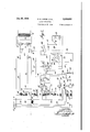
- Fig. 1 is a schematic and diagrammatic representation of the electric circuits and controls of X-ray apparatus constituting a preferred embodiment of this invention.
- Fig. 2 is a schematic representation of the portion of Fig. 1 within the area enclosed by the dotted lines particularly showing in detail the electric circuits and controls of an electronic Ma. S. timer of the embodiment represented by Fig. 1.
- Figs, 3 and 4 are views diagrammatically illustrating certain time-voltage relationships in the timer circuits.
- the objects and advantages of this invention are attained in part by the provision in the circuits for controlling the fiow and magnitude of the current through an X-ray tube, of a manually variable timing device which operates to initiate the flow of current through the X-ray tube and to terminate the current flow after a predetermined time interval.
- This time. intervalv in turn is adapted to be automatically inversely varied in direct proportion to any manually effected change in the magnitude of the current which flows through the tube whereby a preselected Ma. S. factor may be maintained constant regardless of the current employed.
- the timing device is electrically coupled in the circuits of the X-ray apparatus so as to initiate and interrupt the current flow in the primary circuit of the transformer which supplies high voltage current to the X-ray tube.
- an electronic Ma. S. timer generally designated by the numeral I 0, Fig. l, is electrically coupled in the low voltage A. C. circuit formed by the auto-transformer II, the primary coil of the X-ray transformer I2 and the leads I3 and I4, all as best shown in Fig. 2.
- Voltage control in this circuit is effected by means of a pair of switch arms I5 and I6 which connect the leads I3 and I4, respectively, to respective banks of taps I! and IS on the auto transformer II.
- Major and minor control of the voltage is effected by the banks I1 and I8, respectively, through establishment of a predetermined ratio of turns in the auto-transformer.
- PSV peak kilo voltage
- the output of the X-ray transformer I2 is sup-.-
- full-wave rectification of the transformer output is provided for.
- the secondary of the transformer I2 is connected to a bank of rectifier valve tubes, four in number, by leads 2! and 22.
- the valve tubes 20 are connected in the known manner so as to effect full-wave rectification of the input voltage, the output of the valve tubes being delivered through the leads 23 and 26 to the anode 25 and the cathode 26 of the X-ray tube 37.
- the direct current magnitude in the X-ray tube circuit is measured by a milliammeter 28 in the lead 23.
- the magnitude of the current in the X-ray tube circuit is controlled by the temperature of the X-ray tube filament (or filaments) and of the valve tube filaments. As embodied, these filaments are heated by power supplied thereto from suitable filament transformers, the power input to each of which is varied simultaneously to effect the desired milliamperage change in the X-ray tube circuit. As here embodied, the filament of the X-ray tube 21 is supplied with power in the known manner by a filament transformer 23 whose output is delivered to the X-ray tube filament (cathode) by the leads 30 and 3
- the power input to the filament transformer 25 is obtained from the auto-transformer II through leads '32 and 33, the former having in series therewith an 'ammeter 34 a resistor 35 and a switch arm 36.
- the resistor 35 may be continuously or progressively variable.
- the resistor 35 is provided with a series of taps, five in number, adapted to be engaged successively by the switch arm 36 so that clockwise movement of the switch arm from the position shown will increase the filament current.
- the switch arm 36 forms part of one deck of a multi-deck, multi-position switch which, as here embodied, is provided with two additional decks having the switch arms 31 and 38, respectively, mechanically coupled with the switch arm 36 by link mechanism diagrammatically indicated at 36. Equal simultaneous angular movements of the switch arms is effected by rotation of the common switch arm shaft.
- the switch arm 37 functions to control the filament current in the valve tubes 23.
- the leads '33 and 32 are connectedb'y the leads 46 and M, respectively, to filament transformers 42, 43 and '44, as shown.
- the switch arm 31, lead 4!, and re sistor 45 form a circuit.
- the resistor 45 may be continuously, or progressively, variable, the particular form being chosen to conform to that of the companion resistor '35.
- the resistor 45 is provided with a series of taps, five in number, adapted to be engaged successively by the switch arm '31 so that clockwise movement from the position shown will cut out resistance so as to eifect an increase in the valve tube filament temperature simultaneously with an increase in the X-ray tube filament temperature.
- the switch arms 36 and 31 together operate to regulate the milliamperage in the X-ray tube high voltage circuit.
- the switch arm 38 of the multi-deck switch functions to insert in the circuit of the timer ID, as is more fully described hereinafter, a value of timing capacitance which, at each position of the switch arm, is .so correlated tothe milli'amperage determined by the position of the switch arms 36 and 31 as to maintain the same basic Ma. S. factor at all times.
- the switch arm 33 is adapted to engage successively a series of contacts, five in number, respectively connected to one side of respective condenser units C6 to C10 inclusive.
- Variation of the basic Ma. S. factor at each position of the switch arms 36 to 38 inclusive maybe effected, however, by rotation of the numbered dial 46, Fig. 1, which represents a correspondingly numbered switch arm as best appears in Fig. 2 and is more fully described hereinafter.
- a main wall switch 49 couples the leads 4'! and 48 with the auto-transformer I I through leads 50 and 5
- the switch points 53 and 54 are closed by movement of the solenoid plunger '55 when actuated by the fiow of current through the solenoid coil 56.
- the transformer 51 has its secondary-winding in parallel circuit arrangement with a -pair of circuits of which the first is constituted by a heating coil 63, the second being a delayed action circuit constituted by the solenoid coil 56 and leads 64 and 65.
- the circuit through the lead 65 is adapted to be completed by closing of a pair of contacts 66 therein when actuated by a thermo-bar 61 energizedby the heating coil63.
- closing :of the main switch 49 and 'of'tlie switch 62 is not followed by closing of the solenoid switch 52 until delayed closure of the contacts 66 permits current to flow in the solenoid circuit.
- the timer l6 when set in operation functions to initiate the flow of current through the primary coil of the X-ray transformer i2 and-to terminate this flow after the elapse of -a predetermined interval of time which is automatically varied inversely in direct proportion to a change in the magnitude of the milliamperage in the X- ray tube 2'Letfected by the switches 36 and 31.
- the timer comprises essentially-an electronic relay tube circuit energizable to permit the 'flowof alternating current in the primary coil of the X-ray transformer l2, and, an electronic timing circuit by means of which the relay tube circuit is energized for a predetermined time interval.
- the relay circuit comprises a pair of grid controlled gas tubes iii-and H whose grids are normally negatively biased so that on currentflows in the plate-cathode circuit of either.
- a center tapped resistor'T-Z Situated inthe lead it to the primary of the'X-ray transformer i2 is a center tapped resistor'T-Z.
- the plates of the tubes '10 and H are connected to the lead 14 ateither side of this resistor, the plate of tube 16 by the lead l-3, and the plate of tube H by the lead 1 5.
- ] and H is obtained from the D.-C. voltage drop across a section of a continuously variableresistor H5 in the timin circuit as is described more fully hereinafter.
- the cathode heaters of the tubes 19 and H are supplied with power from a filament transformer 15 having a split primary winding connected by leads 16 and 11 to terminals A and B, respectively, of the timer I9.
- the terminal A is connected by a lead 18 to the power lead 59 while the terminal .8 is connected by a lead 19 to a ground.
- a neutralizing transformer 83 has its primary winding shunted across the leads I3 and I4.
- the secondary of the transformer consists of two windings 84 and 85, the former being connected at one terminus by a lead 86 containing a resistor 88 of high value to the grid of the tube 19 and the latter being connected at one terminus by a lead 81 containing a resistor 89 of high value to the grid of the tube 1 I.
- the remaining terminals are connected by leads 99 and 9I to the secondary windings 92 and 93 of a gridbiasing transformer 94 to be more fully described hereinafter. It is essential that the secondary windings 84 and 85 be properly phased to obtain the desired neutralization.
- the grids of tubes 19 and H are normally negatively biased relative to the cathodes by a negative D. C. potential of a fixed value. This poten tial is supplied by the timing circuit. These grids are alternately carried positive by the positive half of the A. C. potential supplied by the respective secondary windings 92 and 93 of the gridbiasing transformer 94 in conjunction with a positive D. C. potential supplied by the timing circuit. The windings 92 and 93 are therefore suitably phased to accomplish this object. Condenser units Cl and C2 of suitable capacity are shunted across the grid-cathode leads of the tubes 19 and H, respectively, to prevent switching surges from momentarily changing the grid to cathode potential of these tubes and allowing them-to fire.
- the timing circuit comprises a rectifier tube 95; grid controlled gas tubes 96 and 91 which function to initiate and terminate, respectively, the timing cycle; a bank or fixed capacity condenser units C6 to C inclusive, for inversely varying the timing interval in direct proportion to the magnitude of a change in the milliamperage of the X-ray tube 21; a variable resistor 98 for selectively varying the charging rate of the condensers C6 to C10 inclusive; together with" the necessary resistors, leads, switches and going elements into an operative and useful timing circuit.
- the rectifier tube is energized in the known manner by a transformer 99 having a center tapped secondary winding I99 whose termini are connected by leads I9I and I92, respectively, to either plate of the tube 95 and whose center tap is adapted to be connected to the cathode of thetube 96 through a lead I93 containing switch points I95 and I91 connectable to each other by a solenoid-operated relay switch arm I94 which simultaneously disconnects other switch points I98 and I99 from each other.
- the filament of the tube 95 is heated by the transformer 99 through a secondary winding II9 connected in series with the filament in the usualfashion.
- the filaments of the heater type gasfilled tubes 96 and 91 are powered by the transformer 99 through secondary windingsll3 and H9, respectively, the filament leads in each case being omitted from the drawings for simplifica tion.
- the low and high potential output leads I93 and H2, respectively, of the rectifier unit have shunted thereacross, a variable resistance unit 5 I5 and a filter condenser C3.
- the resistor I I5 is electrically divided into sections H6 and II1 by a lead I I8 which connects the resistor to the common center tap of the secondary windings 92 and 93.
- a potential drop exists across the section II6 so that the grids of the tubes 19 and II are, in consequence, impressed with a D. C. potential which is negative relative to the lead H2 and, as will appear more fully hereinafter, relative to the cathodes of the tubes 19 and II.
- This negative D. C. potential on the grids is supplemented by the A. C. output potential of the transformer 94.
- the grids become more and less negative in a uniformly varying fashion but the tubes 19 and H remain in a non-conducting state until the tube 96 fires and the grids of these tubes alternately swing positive.
- the tube 96 is adapted to be placed in circuit with the negative and positive output leads I93 and H2, respectively, of the rectifier 95 so as to initiate the timing cycle and cause the relay tubes 19 and H to become conductive, by means of the solenoid operated switch I99.
- the switch I94 is energized by a solenoid winding I29 connected by the leads I2I and I22 in series with the secondary winding of the transformer I23 whose primary winding is connected by the leads I24 and I25 to the terminals C and D, respectively, which are connected in turn by the leads 59 and 59, respectively, to the main A. C. source through the wall switch 49.
- a push button I26 and auxiliary safety timer I21 are placed in series with the lead I22 for closing the circuit through winding I29 so as to move the switch arm I99 into engagement with the switch points I95I91, the switch points I98 and I99 being disengaged from each other at the same time for a purpose described more fully hereinafter.
- the output voltage of the rectifier unit is applied to the gas tube 96 through the negative lead I93, connected to its cathode and its suppressor grid, and through the positive lead H2.
- the latter is connected to the plate of the tube through a pair of series connected plate load resistors I28 and I29 whose common terminal is connected by a lead I39 to the electrically neutral center tap,
- the resistor I29 functions when the tube. 96 is firing to provide a D. C. voltage drop which is utilized partially to cancel the voltage drop across thexresistor section H6.
- the biasing transformer windings 92 and 93 supply the required additional A. C. voltage necessary to carry the grids of tubes I9 and H, respectively, positive when the plate of each of the tubes I9 and 'II is positive;
- Firing of the gas tube 99 is instituted by swinging; its control grid positive relative to its cathode through the medium of a suitable grid biasing. circuit.
- the tube 99 is caused to fire within a range of, for example, about thirty degrees (30) to either side of the start of each cycle of the main voltage wave and continues to fire throughout the cycle in each instance.
- the biasing circuit consists of a transformer I3! whose primary winding is connected to the power leads I2I and I22.
- the secondary winding of the transformer I3I is con.- nected to the tube cathode through a condenser unit C5 by leads I32 and Hi3, as shown, and is connected to the control grid of the tube 96 by means of a lead I33.
- a resistor I34 is shunted across the leads I32 and I33.
- the voltagewave across the resistor I34 is, in consequence, substantially 90 leading in phase with relation to the main A. C. voltage wave.
- a grid condenser C4 which is shunted by a resistor I35 is provided in the lead I33.
- the voltage drop across the resistor I34 is utilized to charge the condenser C4 by grid rectification in the direction indicated.
- The. capacity of the condenser C4 is preferably such that the grid of tube 99 will become positive for a small part only of the positive half cycle of the voltage wave across the resistor I34, as is shown in Fig. 3. Since the resistor voltagewave leads the main A. C. voltage wave by approximately 90, the control grid will be positive and fire the tube 99 at a point on the main A. C. voltage wave within a range of preferably plus or minus 30 from the start of each cycle of the main wave as is shown in Fig. 3.
- the resistor I35- may or may not be required. If it is, its value should be as high as possible and should not be reduced below that at which the tube 96 will fire consistently.
- the current flow in tube 93 produces a voltage drop across resistor I29 which partially cancels the voltage drop across resistor I I6 by which the grids of tubes I9 and II are normally negatively biased.
- This condition is shown in Fig. 4.
- the additional voltage for cancelling the remainder of the drop across resistor H9 and for positively alternately biasing these grids is provided by the respective secondary winding of the transformer 94 whose alternating E. M. F. supplements the drop across I29 in amount and phase relationship so as to cancel the negative bias on the respective grids at the proper moment and thereafter to swing each grid alternately positive so as to initiate firing of these tubes.
- This condition is diagrammatically illustrated in Fig. 4.
- transformer 94 adds an alternating E. M. F. in the grid circuit of each tube I0 and II in such a way as to carry the gridsalternately positive at about the 28 point-of each half cycle when the timing circuit is on.
- the circuit is easily'adjustedfor any reasonable power factor which maybe encountered, by adjusting the slider on resistor M5 to the proper position for the particular condition.
- the output voltage of the rectifier is applied to the series connected resistors I28 and I29 and to one of the condensers C6 to C10 inclusive which charges up at a rate fixed by the setting of the continuously or. progressively variable resistor 98.
- the timing cycle is adapted to be terminated after the elapse of apredetermined time interval the magnitude of which is variablesimultaneously with and in inverse relation to the magnitude of any change in the milliamperage in theX-ray tube current.
- termination of the timing cycle is effected by means of the gas tube 9! and any one of condensers C6 to C10.
- the gas tube 91 is caused tofunction at the proper moment by means of the respective condenser units Cs: to C10 so as to neutralize the positive potential being supplied to the main grids in consequence of the potential drop across the plate loadresistor I29.
- the plate of the tube 91 is connected by the lead. I39 to the positive lead H2 of the rectifier While the cathode and suppressor grid of the tube are connected. to the lead I39;
- the plate' of the tube 9'! is positive relative to its cathode, while the tube 96 is firing, by the voltage drop' across the resistor I29
- the tube 91 ismaintained ina non-conducting state until the selected. time interval has elapsed and, as embodied, this'is accomplished by maintaining the control grid of the tube negative with relation to its cathode during this interval.
- control grid is connected by a lead I31, containing a grid leak I38, to the switch arm 46 which is adapted to be manually rotated in a clockwise direction so as to engage successively a series of taps on the variable resistance 98 which latter is inserted in the high potential lead H2.
- variable resistance 98 may consist of 'a series of timing resistors each preferably of a fixed value. As resistanceis cut into the condenser charging circuit, by counterclockwise movement of switch arm 46, the basic chargingrate of the selected condenser unit of the condenser units C6 to C10 inclusive will be decreased.
- the switch arm 46- isin turn connected by a lead I 39 to one side of each of the condenser units Cs to C10 inclusive, the opposite-side of eachof which is connectedto' one of a series of taps respectivejly adapted to be engaged successively by a;
- switch arm 38 upon rotation in a clockwise direction of the multi-position, multiple-deck milliampere selector switch previously described.
- the switch arm 38 is in turn connected by the lead I40 to the plate end of the resistor I28 and also to the condenser discharge contact III! of the solenoid switch IIl I whose opposed contact IE9 is connected by a lead MI, containing a condenser discharge resistor I42, to the common side of the condensers C6 to C10 inclusive.
- the condenser units Cato C10 inclusive are preferably of a type which will ensure that the capacity of the respective units will remain substantially constant throughout an appreciable range of operating temperatures and over a long period of time. Units of the mica or paper type are therefore to be preferred over units of the electrolytic type since the latter have less constant time-temperature characteristics.
- the capacitance of the respective condenser units C6 to C10 inclusive is chosen so as to reduce progressively the timinginterval as theX-ray tube current is increased so as to preserve a constant current-time relationship.
- the relationship is such that the increase in milliamperage resulting from clockwise movement of the coupled switch arms 36 and 31 from the position shown in Fig. 1 to the next tap on the variable resistor banks 35 and 45, respectively, will be ac integrated automaticallyby a decrease in capacitance resulting from a corresponding movement of thecoupled switch arm 33 from the condenser unit Co, for example, to the condenser unit C7 of lower capacitance.
- theresistor units 35 and 45 arerespectively provided with taps, fivein number, each of which will effect a doubling of the milliamperage obtainable from thenext preceding tap. Forgexample, techniques of 25, 50, 100, 200 and 400 milliamperes may be provided for.
- the condenser units Cato C10 inclusive are respectively of a capacity which is one half that of the next preceding condenser unit.
- values of capacitance of 16, 8, 4, 2 and, mfds., respectively, for the condenser units C6, C1, Ca, Ca and C10, respectively, would provide in conjunction with techniques of 25, 50, 100, 200 and 400, milliamperes, a Ma. S..factor which would be the same in each case. .Thus, for example, if a setting. of the switch arms 36, 31, 38 as in Fig. 1 provided for -8, seconds operation at 25 ma., i. e. an Ma. S, factor of 200, positioning of the switch arms on the last tap of eachdeck would provide for of a second operation at 400 ma., i. e. the same Ma. S. factor of 200.
- This base Ma. S. factor maybe decreased by clockwise movement of the switch arm 46 to the minimum obtainable through decreasing the effective value of. the re sistance 98.
- the tube 91 can be'rep-eated only by discharging the condenser unit which is operative in the circuit. This is eifected by releasing the push button I29. In consequence, the solenoid I94 moves to the position shown in Fig. 2 and the condenser charge is dissipated through the resistor Hi2, I
- the auxiliary safety timer I21 is intended to limit automatically the possible exposure time should the main electronic timer be set to provide a time current condition exceeding the normal safety rating of the X-ray tube.
- the timer I21 comprises a motor driven synchronous timing device or other suitable me,- chanical timing device which will open the circuit throughthe lead I22 should the main electronic timer be set for an Ma. S. factor in excess of the rating, or safety limits of the X-ray tube.
- setting of the auxiliary timer I2'I is accomplished by utilizing the shaft, or an ex tension of the shaft, of the multi-deck, multiposition, milliampere selector switch to pre-set the timer so that as the milliamperes are increased from the lowest rating to the highest rating the shaft will automatically set the motor driven synchronous safety timing device to limits which will be within the ratings of the X-ray tube.
- the switch I46 in its open position, as shown in Fig. 2, permits the timer to control the duration of operation of the relay tubes. Closing of the switch results in the same negative D. 0. potential occasioned by the drop across the resistor section IIB being impressed on the grid and cathode of each of the relay tubes III and II. In consequence, the-alternating E. M. F. supplied by the secondary The system shown in Fig. '1 is placed in opera tion by closing the main wall switch 49 as a first step.
- the relay tubes III and II are preferably gas filled tubes of suitable capacity, such as, for example, type C-6-J tubes and may be lit continuously with no loss in filament emission.
- the switch 62 which controls voltage'to the timer section III, is closed as a next step so as to light the filaments of the tubes 95, 96 and '91.
- the tubes 96 and 91 are gas filled tubes, such as, for example, type 2050 while the rectifier tube is preferably type 523.
- Closureof the switch 62 is followed in a short time, e. g. around 10 seconds, by automatic 010-- sure of the solenoid operated main control switch 52 consequent upon delayed closure of the contacts 65.
- the system is now ready for oper ation either for radiography or for fluoroscopy.
- the PKV decided upon is set by adjustment of the autotransformer. controls I5 and I8.
- the timer is then's'et for theMa. S. factor deemed proper for the particular operation to, be undertaken, moving the switch arm to the selected Ma. S. factor, such as, for example, 200 Ma. S., as shown in the dial window in Fig. .1.
- Any one of the techniques obtainable by a setting of the miniamperage selector switch such as, for example, 25, 50, 100, 200 or 400 milliamperes technique, may then be employed by simultaneous movement of the switch arms 36, .31, 38 to the desired setting.
- the same milliampere-second relationship will obtain upon pressing the push button 1262110 initiate the timing cycle. If the Ma. S. factor employed would exceed the rated capacity of the X-raytube, the auxiliary timing device will operate toopen the timing circuit before the preset timing cycle has been completed.
- the footswitch I45 is closed and the X-ray tube will operate without interruption until the switch is again opened.
- Apparatus fortimingjX-ray exposures comprising means ;for varying the magnitude of the X-ray tube current; and, means forautomatically-interrupting said current upon the elapse'of a selected time interval, said interrupting means including means set by said :current varying means for proportioning the timing .interval with relation to the magnitude of said tube current so as to provide the sametime-current relationship at each yalue 0f the tube current.
- Apparatusfortirrring X-ray exposures comprising means for --varying the magnitude of the X ray tubgcurrent; and, means for automaticallyyinterrupting said current upon the relapse 011a rselected time interval, said interrupting means including :means set y said current varyin means for proportioning the timing interval with relation to the magnitude of said tube cur- ,rent so as to provide the same time-currentrelationship at each value of the tube current; and. means for independently varying said relationship at each value of the tube current.
- Apparatus for timing Xeray exposures comprising means for varying in ya step-wise fashion the magnitude of the X-ra-y tube current; and, means :for automatically interrupting said current upon the elapse ofa selected time interval, said interrupting means includinga bank of con denser un ts .for propertioningthe timing interval with :relation to the magnitude of the tube current :so .as to provide the same timeecurrent relationship at each value :of the tube current, and means actuated by said first mentioned means ;for selecting a condenser unit of the required capacity from said bank with each stepwise variation in the magnitude 50f said current.
- a timing device comprising ,a mu1ti-deck, multi-position switch of which one deck controls the magnitude of the current in a current conducting circuit; acendenser circuit which the value of the capacitance is controlled by another deck of said switch, said value being inversely varied upon .a change in the setting .of said switch in direct proportion to the magnitude of t ruption of said current when said capacitance unit has attained a predetermined charge.
- a timing device comprising a multi-deck, multi-position switch of which one deck controls the magnitude of the current in a current conducting circuit; a condenser circuit in which the value of the capacitance is controlled by another deck ;of said switch, said value being inversely varied upon a change in the setting of said switch in direct proportion to the magnitude of the accompanying change in said current; and, a control tube having a voltage sensitive element connected to said condenser circuit so as to respend to changes in the voltage across the capacitance unit in said circuit and, relay means in circuit with said control tube and said current conducting circuit for interrupting said current when said capacitance unit has attained a predetermined charge.
- a timing device comprising .a multi-deck, multi-position switch of which one deck controls the magnitude of the current in acurrcnt .conducting circuit; a condenser circuit in which the value of the capacitance is controlled by another deck of said switch, said value being ,inversely varied upon a change in the Setting of said switch in direct proportion to themagnitude of the accompanying change in saidcurrent; and, a control tube having a voltage sensitive element connected to said condenser circuit so as to respond to changes in the voltage across the capacitance unit in said circuit; and, relay means in circuit with said control tube and said current conducting circuit for interrupting said current when said capacitance .unit has attained a predetermined charge, said relay means comprising a voltage controlled thermionic valve tube.
- Apparatus for timing .X-ray exposures comprising ta multi-deck, rmulti pos'ition switch of which one deck controls the magnitude of the X- ray tubecurrent; relay means in-the primary circuit of theX-ray transformerrfor interruptingthe flow of current in said circuitupon the elapse of .a selected time interval; and, means for actuating said relay means comprising a control tube having a voltage-sensitive element, and a bank of timing condenser units respectively, selectively connectable to said element by another deck of saidswitch, said condenser unit respectively having a capacity which will provide the same timecurrent relationship for each value oftheIX-ray tubecurrent selected by said switch.
- a paratus for timing X-ray exposures comprising means for varying the magnitude of the X-ray tube current; relay means .for interrupting the flow of said current upon the elapse of .a predetermined time interval; and, means for actuating said relay means upon the elapse of said predetermined interval, said actuating means comprising a timing circuit including a bank .of timing condenser units ofdifferent capacities, means for selectively connecting the respective condenser units in said circuit .so as to obtain the same time-current relationship for each value of the tube-current, and a control tube connected to said relay means, said control tube having a voltage-sensitive element connected to said condensers so as to respond to changes in the voltage across the condenser in circuit whereby said relay means will be actuated when said condenser has acquired a predetermined charge.
- Apparatus for timing 'X-ray exposures comprising means for varying the magnitude of the X-ray tube current; relay means for interrupting the flow of said current upon the elapserofapredetermined time interval; and, means for actuating said relay means upon the elapse of said predetermined interval, said actuating means comprising a timing circuit including a bank of timing condenser units of different capacities, means for selectively connecting the respective condenser units in said circuit so as to obtain the same time-current relationship for each value of the tube-current, and a control tube connected to said relay means, said control tube having a voltage-sensitive element connected to said condensers so as to respond to changes in the voltage across the condenser in circuit whereby said relay means will be actuated when said condenser has acquired a predetermined charge, and means for independently varying the charging rate of said condensers.
- a milliampere-second timing device for timing X-ray exposures comprising a multiple-deck, multi-position switch of which one deck controls the magnitude of the X-ray tube current; a condenser circuit in which the value of the capicitance is controlled by another of said decks so as to provide the same time-current relationship for each value of the X-ray tube current selected by said switch; condenser charging means; relay means; and, a control tube for actuating the relay means, said control tube having a voltage-sensitive element connected to said condenser circuit so as to respond to voltage changes therein, whereby said control tube will become operative and actuate said relay means when said condenser circuit has acquired a predetermined charge.
- Apparatus for timing X-ray exposures comprising thermionic valve tube relay means in the primary circuit of the X-ray transformer; means for negatively biasing said valve tubes so as to render them normally non-conductive; means for neutralizing said negative bias to initiate the timing cycle comprising separate sources of direct current and alternating current bias potential connected to said valve tubes; and, means for neutralizing the positive biasing potential after a predetermined time interval so as to terminate the timing cycle.
- Apparatus for timing X-ray exposures comprising thermionic valve tube relay means in the primary circuit of the X-ray transformer; means for negatively biasing said valve tubes so as to render them normally non-conductive; means for neutralizing said negative bias to initiate the timing cycle comprising separate sources of direct current and alternating current bias potential connected to said valve tubes; and, means for neutralizing the positive biasing potential after a predetermined time interval so a to terminate the timing cycle, said means comprising a timing condenser and a control tube in parallel circuit arrangement with said source of D.
- control tube having a voltage sensitive element connected to said condenser so as to respond to changes in voltage across said condenser whereby said control tube may be caused to fire when said condenser acquires a predetermined charge and thereby neutralize said positive biasing potential.
Landscapes
- Health & Medical Sciences (AREA)
- General Health & Medical Sciences (AREA)
- Toxicology (AREA)
- X-Ray Techniques (AREA)
Description
Jan. 25, 1944. 5, AKERS ETAL 2,339,902
I X-RAY APPARATUS Filed March 18, 1942 a Shee tS-Sheet 1 INVENTOR5= Herbert S. Aker's, JZzmes 0. Humphrl'e Jan. 25, 1944. H. s. AKERS ET AL 2,339,902
X-RAY APPARATUS Filed Manch 18, 1942 3 Sheets-Sheet 2 Jan. 25, 1944. H, SAKER ETAL' 2,339,902
X-RAY APPARATUS Filed March 18, 1942 s Sheets-Sheet 3 k Tube 70 Fires Tube 6 FII'QS prop-7 k Voltage- 93 James f/Um Ohries.
ATTO EY Patented Jan. 25, 1944 UNITED STATES X-RAY APPARATUS Herbert S. Akers and James 0. Humphries, Woodclifi Lake, N. J.
Application March 18, 1942, Serial No. 435,176
12 Claims.
This invention relates to improvements in X-ray apparatus.
The quantity of nergy, in the form of X-rays, radiated per unit of time from the anode of an X-ray tube, i. e. the intensity of radiation, is a function of, among other things, the current which flows through the tube. This current is usually measured in milliamperes so that the product of milliamperage and time in seconds gives an energy factor which is a measure of the total energy radiated and may be expressed as milliampere-seconds. This energy factor, for convenience, is sometimes hereinafter referred to as Ma. S.
In the practical application of this principle, it has already been proposed to employ a Ma. S. timing device in conjunction with X ray apparatus such as device being disclosed, for example, in Patent No. 2,136,116 granted November 8, 1938, on an invention of W. W. Mowry. As there embodied, the timing device permits the utilization, at a given milliamperage, of any one of a group of timing elements allocated for use with that particular milliamperage,
If the milliamperage is changed, as an accompaniment, for example, to a change in radiographic technique, a concurrent shift is automatically made to a difierent group of timing elements respectively more suited to the new milliamperage employed.
There are obvious advantages to be realized in the use of X-ray apparatus which would permit the obtainment, automatically and with exactitude, of equal total amounts of X-ray energy at milliamperages which differ widely or narrowly from each other and it is an object of this invention to provide such apparatus.
Another object of this invention is to provide improved X-ray apparatus.
Another object of this invention is to provide X-ray apparatus with which changes in the current flowing through the X-ray tube can be made without an accompanying chang in the Ma. S. factor to which the apparatus may be set.
Another object of this invention i to provide X-ray apparatus with which a change in the current flowing through the X-ray tube can be effected independently of the Ma. S. energy factor selected.
Another object of this invention is to provide an improved timing device for X-ray apparatus.
Other and further objects of this invention will appear from the accompanying drawings, the following description and the appended claims.
In the accompanying drawings which form part of the instant specification and are to be read in conjunction therewith; and in which like numbers refer to like parts throughout the several views;
Fig. 1 is a schematic and diagrammatic representation of the electric circuits and controls of X-ray apparatus constituting a preferred embodiment of this invention; and,
Fig. 2 is a schematic representation of the portion of Fig. 1 within the area enclosed by the dotted lines particularly showing in detail the electric circuits and controls of an electronic Ma. S. timer of the embodiment represented by Fig. 1.
Figs, 3 and 4 are views diagrammatically illustrating certain time-voltage relationships in the timer circuits.
The objects and advantages of this invention are attained in part by the provision in the circuits for controlling the fiow and magnitude of the current through an X-ray tube, of a manually variable timing device which operates to initiate the flow of current through the X-ray tube and to terminate the current flow after a predetermined time interval. This time. intervalv in turn is adapted to be automatically inversely varied in direct proportion to any manually effected change in the magnitude of the current which flows through the tube whereby a preselected Ma. S. factor may be maintained constant regardless of the current employed.
As embodied, the timing device is electrically coupled in the circuits of the X-ray apparatus so as to initiate and interrupt the current flow in the primary circuit of the transformer which supplies high voltage current to the X-ray tube.
As here embodied, an electronic Ma. S. timer generally designated by the numeral I 0, Fig. l, is electrically coupled in the low voltage A. C. circuit formed by the auto-transformer II, the primary coil of the X-ray transformer I2 and the leads I3 and I4, all as best shown in Fig. 2. Voltage control in this circuit is effected by means of a pair of switch arms I5 and I6 which connect the leads I3 and I4, respectively, to respective banks of taps I! and IS on the auto transformer II. Major and minor control of the voltage is effected by the banks I1 and I8, respectively, through establishment of a predetermined ratio of turns in the auto-transformer.
The peak kilo voltage (PKV) in this circuit is measured by the voltmeter I9 shuntedacross the'leads I3 and I4.
The output of the X-ray transformer I2 is sup-.-
plied, after rectification, to the X-ray tube. As embodied, full-wave rectification of the transformer output is provided for. As here embodied, the secondary of the transformer I2 is connected to a bank of rectifier valve tubes, four in number, by leads 2! and 22. The valve tubes 20 are connected in the known manner so as to effect full-wave rectification of the input voltage, the output of the valve tubes being delivered through the leads 23 and 26 to the anode 25 and the cathode 26 of the X-ray tube 37. The direct current magnitude in the X-ray tube circuit is measured by a milliammeter 28 in the lead 23.
The magnitude of the current in the X-ray tube circuit, for a given PKV, is controlled by the temperature of the X-ray tube filament (or filaments) and of the valve tube filaments. As embodied, these filaments are heated by power supplied thereto from suitable filament transformers, the power input to each of which is varied simultaneously to effect the desired milliamperage change in the X-ray tube circuit. As here embodied, the filament of the X-ray tube 21 is supplied with power in the known manner by a filament transformer 23 whose output is delivered to the X-ray tube filament (cathode) by the leads 30 and 3|, the former being also con.- nected to the high voltage lead 2-6. The power input to the filament transformer 25 is obtained from the auto-transformer II through leads '32 and 33, the former having in series therewith an 'ammeter 34 a resistor 35 and a switch arm 36. -As embodied, the resistor 35 may be continuously or progressively variable. As here embodied, the resistor 35 is provided with a series of taps, five in number, adapted to be engaged successively by the switch arm 36 so that clockwise movement of the switch arm from the position shown will increase the filament current.
The switch arm 36 forms part of one deck of a multi-deck, multi-position switch which, as here embodied, is provided with two additional decks having the switch arms 31 and 38, respectively, mechanically coupled with the switch arm 36 by link mechanism diagrammatically indicated at 36. Equal simultaneous angular movements of the switch arms is effected by rotation of the common switch arm shaft.
The switch arm 37 functions to control the filament current in the valve tubes 23. To the accomplishment of this end the leads '33 and 32 are connectedb'y the leads 46 and M, respectively, to filament transformers 42, 43 and '44, as shown. The switch arm 31, lead 4!, and re sistor 45 form a circuit. As embodied, the resistor 45 may be continuously, or progressively, variable, the particular form being chosen to conform to that of the companion resistor '35. As here embodied, the resistor 45 is provided with a series of taps, five in number, adapted to be engaged successively by the switch arm '31 so that clockwise movement from the position shown will cut out resistance so as to eifect an increase in the valve tube filament temperature simultaneously with an increase in the X-ray tube filament temperature. Thus, the switch arms 36 and 31 together operate to regulate the milliamperage in the X-ray tube high voltage circuit.
The switch arm 38 of the multi-deck switch functions to insert in the circuit of the timer ID, as is more fully described hereinafter, a value of timing capacitance which, at each position of the switch arm, is .so correlated tothe milli'amperage determined by the position of the switch arms 36 and 31 as to maintain the same basic Ma. S. factor at all times. As here embodied, the switch arm 33 is adapted to engage successively a series of contacts, five in number, respectively connected to one side of respective condenser units C6 to C10 inclusive. Variation of the basic Ma. S. factor at each position of the switch arms 36 to 38 inclusive maybe effected, however, by rotation of the numbered dial 46, Fig. 1, which represents a correspondingly numbered switch arm as best appears in Fig. 2 and is more fully described hereinafter.
Power is supplied to the auto-transformer I I and to the Ma. S. timer In from an A. C. source, by the .leads 4! and 48. As here embodied, a main wall switch 49 couples the leads 4'! and 48 with the auto-transformer I I through leads 50 and 5| containing switch points 53 and 54, respectively, of a main control switch 52, having a switch arm 55 constituting a solenoid plunger. The switch points 53 and 54 are closed by movement of the solenoid plunger '55 when actuated by the fiow of current through the solenoid coil 56. Power for the operation of the solenoid'is obtained from a suitable transformer 51 to the primary coil of which power is supplied from the leads 58 and 59 through the leads 63 and 6! when the switch 62 is closed. Leads 58 and 59 connect the leads 5| and 56 with terminals C and A-D, respectively, of the timer ID.
The transformer 51 has its secondary-winding in parallel circuit arrangement with a -pair of circuits of which the first is constituted by a heating coil 63, the second being a delayed action circuit constituted by the solenoid coil 56 and leads 64 and 65. The circuit through the lead 65 is adapted to be completed by closing of a pair of contacts 66 therein when actuated by a thermo-bar 61 energizedby the heating coil63. Thus, closing :of the main switch 49 and 'of'tlie switch 62 is not followed by closing of the solenoid switch 52 until delayed closure of the contacts 66 permits current to flow in the solenoid circuit.
The timer l6 when set in operation functions to initiate the flow of current through the primary coil of the X-ray transformer i2 and-to terminate this flow after the elapse of -a predetermined interval of time which is automatically varied inversely in direct proportion to a change in the magnitude of the milliamperage in the X- ray tube 2'Letfected by the switches 36 and 31. As embodied, the timer comprises essentially-an electronic relay tube circuit energizable to permit the 'flowof alternating current in the primary coil of the X-ray transformer l2, and, an electronic timing circuit by means of which the relay tube circuit is energized for a predetermined time interval.
As here embodied, the relay circuit comprises a pair of grid controlled gas tubes iii-and H whose grids are normally negatively biased so that on currentflows in the plate-cathode circuit of either. Situated inthe lead it to the primary of the'X-ray transformer i2 is a center tapped resistor'T-Z. The plates of the tubes '10 and H are connected to the lead 14 ateither side of this resistor, the plate of tube 16 by the lead l-3, and the plate of tube H by the lead 1 5. This negative bias on the tubes 1|] and H is obtained from the D.-C. voltage drop across a section of a continuously variableresistor H5 in the timin circuit as is described more fully hereinafter. When the tube 10 is positively biased and fires, current flows, during the positive half cycle of voltage thereon from its plate to its cathode and thence via lead 14, to which its cathode is connected, to lead l4. When tube 1I fires, during the other half cycle, current flows from the lead I4 via lead 14 to the plate of tube H and thence via the tube cathode to lead I4. Thus, an alternating current may be made to flow in the primary of the transformer I2 so long as the grids of the tubes 19 and H are alternately positively biased.
The cathode heaters of the tubes 19 and H are supplied with power from a filament transformer 15 having a split primary winding connected by leads 16 and 11 to terminals A and B, respectively, of the timer I9. The terminal A is connected by a lead 18 to the power lead 59 while the terminal .8 is connected by a lead 19 to a ground. Thus, it will be observed that by closing the main wall switch 49 current will flow in the primary coil of the filament transformer 15 whose split secondary has a section 8I connected to the filament of tube 19 and a section 82 connected to the filament of the tube 1 I The resistor 12 has substantially A. C. line voltage impressed across it when the tubes 19 and H are non-conducting, so that the midpoint of the resistor difiers from the cathode potential of aech tube by one half the A. C. line voltage. This A. C. voltage must be neutralized so that any D. C. potential impressed by the timing circuit upon the grids of tubes 19 and H in one direction will make both grids positive, and will make both grids negative if impressed in the other direction. As here embodied a neutralizing transformer 83 has its primary winding shunted across the leads I3 and I4. The secondary of the transformer consists of two windings 84 and 85, the former being connected at one terminus by a lead 86 containing a resistor 88 of high value to the grid of the tube 19 and the latter being connected at one terminus by a lead 81 containing a resistor 89 of high value to the grid of the tube 1 I. The remaining terminals are connected by leads 99 and 9I to the secondary windings 92 and 93 of a gridbiasing transformer 94 to be more fully described hereinafter. It is essential that the secondary windings 84 and 85 be properly phased to obtain the desired neutralization.
The grids of tubes 19 and H are normally negatively biased relative to the cathodes by a negative D. C. potential of a fixed value. This poten tial is supplied by the timing circuit. These grids are alternately carried positive by the positive half of the A. C. potential supplied by the respective secondary windings 92 and 93 of the gridbiasing transformer 94 in conjunction with a positive D. C. potential supplied by the timing circuit. The windings 92 and 93 are therefore suitably phased to accomplish this object. Condenser units Cl and C2 of suitable capacity are shunted across the grid-cathode leads of the tubes 19 and H, respectively, to prevent switching surges from momentarily changing the grid to cathode potential of these tubes and allowing them-to fire.
The timing circuit, as her embodied, comprises a rectifier tube 95; grid controlled gas tubes 96 and 91 which function to initiate and terminate, respectively, the timing cycle; a bank or fixed capacity condenser units C6 to C inclusive, for inversely varying the timing interval in direct proportion to the magnitude of a change in the milliamperage of the X-ray tube 21; a variable resistor 98 for selectively varying the charging rate of the condensers C6 to C10 inclusive; together with" the necessary resistors, leads, switches and going elements into an operative and useful timing circuit. I
The rectifier tube is energized in the known manner by a transformer 99 having a center tapped secondary winding I99 whose termini are connected by leads I9I and I92, respectively, to either plate of the tube 95 and whose center tap is adapted to be connected to the cathode of thetube 96 through a lead I93 containing switch points I95 and I91 connectable to each other by a solenoid-operated relay switch arm I94 which simultaneously disconnects other switch points I98 and I99 from each other.
The filament of the tube 95 is heated by the transformer 99 through a secondary winding II9 connected in series with the filament in the usualfashion. The filaments of the heater type gasfilled tubes 96 and 91 are powered by the transformer 99 through secondary windingsll3 and H9, respectively, the filament leads in each case being omitted from the drawings for simplifica tion.
The low and high potential output leads I93 and H2, respectively, of the rectifier unit have shunted thereacross, a variable resistance unit 5 I5 and a filter condenser C3.
The resistor I I5 is electrically divided into sections H6 and II1 by a lead I I8 which connects the resistor to the common center tap of the secondary windings 92 and 93. A potential dropexists across the section II6 so that the grids of the tubes 19 and II are, in consequence, impressed with a D. C. potential which is negative relative to the lead H2 and, as will appear more fully hereinafter, relative to the cathodes of the tubes 19 and II. This negative D. C. potential on the grids is supplemented by the A. C. output potential of the transformer 94. The grids become more and less negative in a uniformly varying fashion but the tubes 19 and H remain in a non-conducting state until the tube 96 fires and the grids of these tubes alternately swing positive.
The tube 96 is adapted to be placed in circuit with the negative and positive output leads I93 and H2, respectively, of the rectifier 95 so as to initiate the timing cycle and cause the relay tubes 19 and H to become conductive, by means of the solenoid operated switch I99.
The switch I94 is energized by a solenoid winding I29 connected by the leads I2I and I22 in series with the secondary winding of the transformer I23 whose primary winding is connected by the leads I24 and I25 to the terminals C and D, respectively, which are connected in turn by the leads 59 and 59, respectively, to the main A. C. source through the wall switch 49.
A push button I26 and auxiliary safety timer I21 are placed in series with the lead I22 for closing the circuit through winding I29 so as to move the switch arm I99 into engagement with the switch points I95I91, the switch points I98 and I99 being disengaged from each other at the same time for a purpose described more fully hereinafter.
Upon closure of the contacts I95 and I91, the output voltage of the rectifier unit is applied to the gas tube 96 through the negative lead I93, connected to its cathode and its suppressor grid, and through the positive lead H2. The latter is connected to the plate of the tube through a pair of series connected plate load resistors I28 and I29 whose common terminal is connected by a lead I39 to the electrically neutral center tap,
other devices necessary for coordinatingthe foreof-theresistor I2. Thus, until the tube 99, fires, the cathodes of tubes I9. and 'II will be: at the potential of lead I I2, with reference to which the grids are negative, by the voltage drop across I IS.
The resistor I29 functions when the tube. 96 is firing to provide a D. C. voltage drop which is utilized partially to cancel the voltage drop across thexresistor section H6. The biasing transformer windings 92 and 93supply the required additional A. C. voltage necessary to carry the grids of tubes I9 and H, respectively, positive when the plate of each of the tubes I9 and 'II is positive;
Firing of the gas tube 99 is instituted by swinging; its control grid positive relative to its cathode through the medium of a suitable grid biasing. circuit. Preferably, the tube 99 is caused to fire within a range of, for example, about thirty degrees (30) to either side of the start of each cycle of the main voltage wave and continues to fire throughout the cycle in each instance.
As here embodied, the biasing circuit consists of a transformer I3! whose primary winding is connected to the power leads I2I and I22. The secondary winding of the transformer I3I is con.- nected to the tube cathode through a condenser unit C5 by leads I32 and Hi3, as shown, and is connected to the control grid of the tube 96 by means of a lead I33. A resistor I34 is shunted across the leads I32 and I33. The voltagewave across the resistor I34 is, in consequence, substantially 90 leading in phase with relation to the main A. C. voltage wave. A grid condenser C4 which is shunted by a resistor I35 is provided in the lead I33.
The voltage drop across the resistor I34 is utilized to charge the condenser C4 by grid rectification in the direction indicated. The. capacity of the condenser C4 is preferably such that the grid of tube 99 will become positive for a small part only of the positive half cycle of the voltage wave across the resistor I34, as is shown in Fig. 3. Since the resistor voltagewave leads the main A. C. voltage wave by approximately 90, the control grid will be positive and fire the tube 99 at a point on the main A. C. voltage wave within a range of preferably plus or minus 30 from the start of each cycle of the main wave as is shown in Fig. 3.
The resistor I35-may or may not be required. If it is, its value should be as high as possible and should not be reduced below that at which the tube 96 will fire consistently.
The current flow in tube 93 produces a voltage drop across resistor I29 which partially cancels the voltage drop across resistor I I6 by which the grids of tubes I9 and II are normally negatively biased. This condition is shown in Fig. 4. The additional voltage for cancelling the remainder of the drop across resistor H9 and for positively alternately biasing these grids is provided by the respective secondary winding of the transformer 94 whose alternating E. M. F. supplements the drop across I29 in amount and phase relationship so as to cancel the negative bias on the respective grids at the proper moment and thereafter to swing each grid alternately positive so as to initiate firing of these tubes. This condition is diagrammatically illustrated in Fig. 4.
If the grids of the relay tubes were made positive solely by D. C, voltage, any unbalance in current conduction between them would cause a D. C. component to flow through the primary of the X-ray transformer I2 tending to saturate it and aggravate the unbalance. This tendency isovercome in theinstant embodimentby retarding the firingwith the maingrids to apoint at least 2 or 3 later. than the natural zero of the alternating current. Thus, as appears from Fig. 4, firing of the relay tubes I9 and 1| must be restrained throughoutan initial portion of each half cycle of the-main voltage wave. The extent of this restraint will be determined by the power factor of the alternating current, Thus, by way of example, if the power factor ofthis current is firing must be restrained for the firstZB of each half cycle of the main voltage wave. This condition is depicted in Fig. 4 wherein it will be observed that transformer 94 adds an alternating E. M. F. in the grid circuit of each tube I0 and II in such a way as to carry the gridsalternately positive at about the 28 point-of each half cycle when the timing circuit is on. The circuit is easily'adjustedfor any reasonable power factor which maybe encountered, by adjusting the slider on resistor M5 to the proper position for the particular condition.
When the tube 99 fires to initiate the timing cycle, the output voltage of the rectifier is applied to the series connected resistors I28 and I29 and to one of the condensers C6 to C10 inclusive which charges up at a rate fixed by the setting of the continuously or. progressively variable resistor 98.
The timing cycle is adapted to be terminated after the elapse of apredetermined time interval the magnitude of which is variablesimultaneously with and in inverse relation to the magnitude of any change in the milliamperage in theX-ray tube current. As embodied, termination of the timing cycle is effected by means of the gas tube 9! and any one of condensers C6 to C10. The gas tube 91 is caused tofunction at the proper moment by means of the respective condenser units Cs: to C10 so as to neutralize the positive potential being supplied to the main grids in consequence of the potential drop across the plate loadresistor I29.
As here embodied, the plate of the tube 91 is connected by the lead. I39 to the positive lead H2 of the rectifier While the cathode and suppressor grid of the tube are connected. to the lead I39; Thus, the plate' of the tube 9'! is positive relative to its cathode, while the tube 96 is firing, by the voltage drop' across the resistor I29 The tube 91 ismaintained ina non-conducting state until the selected. time interval has elapsed and, as embodied, this'is accomplished by maintaining the control grid of the tube negative with relation to its cathode during this interval. As here embodiedthe control grid is connected by a lead I31, containing a grid leak I38, to the switch arm 46 which is adapted to be manually rotated in a clockwise direction so as to engage successively a series of taps on the variable resistance 98 which latter is inserted in the high potential lead H2.
The variable resistance 98, as here embodied, may consist of 'a series of timing resistors each preferably of a fixed value. As resistanceis cut into the condenser charging circuit, by counterclockwise movement of switch arm 46, the basic chargingrate of the selected condenser unit of the condenser units C6 to C10 inclusive will be decreased.
The switch arm 46- isin turn connected by a lead I 39 to one side of each of the condenser units Cs to C10 inclusive, the opposite-side of eachof which is connectedto' one of a series of taps respectivejly adapted to be engaged successively by a;
switch arm 38 upon rotation in a clockwise direction of the multi-position, multiple-deck milliampere selector switch previously described. The switch arm 38 is in turn connected by the lead I40 to the plate end of the resistor I28 and also to the condenser discharge contact III! of the solenoid switch IIl I whose opposed contact IE9 is connected by a lead MI, containing a condenser discharge resistor I42, to the common side of the condensers C6 to C10 inclusive.
Thus, it will be observed that before the condensers have received any charge the potential drop across the resistor I28 will render the control grid of tube 97 negative relative to its cathode. As current fiows in the condenser circuit, the condenser Cs, for example, whose tap is engaged by the switch arm 38, will charge up at a rate fixed by the value of resistance selected by the setting of the switch arm 49 until the charge on the condenser Cs equals the drop across the resistor I28. At that time the control grid of tube 91 will cease to be negative and will allow tube 91 to conduct. This amounts to shortcircuiting the resistor I ,29, the voltage drop across I29 disappears and tubes 79 and II cease to conduct.
The condenser units Cato C10 inclusive, as embodied, are preferably of a type which will ensure that the capacity of the respective units will remain substantially constant throughout an appreciable range of operating temperatures and over a long period of time. Units of the mica or paper type are therefore to be preferred over units of the electrolytic type since the latter have less constant time-temperature characteristics.
The capacitance of the respective condenser units C6 to C10 inclusive is chosen so as to reduce progressively the timinginterval as theX-ray tube current is increased so as to preserve a constant current-time relationship. As embodied, the relationship is such that the increase in milliamperage resulting from clockwise movement of the coupled switch arms 36 and 31 from the position shown in Fig. 1 to the next tap on the variable resistor banks 35 and 45, respectively, will be ac companied automaticallyby a decrease in capacitance resulting from a corresponding movement of thecoupled switch arm 33 from the condenser unit Co, for example, to the condenser unit C7 of lower capacitance. As here embodied, theresistor units 35 and 45 arerespectively provided with taps, fivein number, each of which will effect a doubling of the milliamperage obtainable from thenext preceding tap. Forgexample, techniques of 25, 50, 100, 200 and 400 milliamperes may be provided for. In conforme ance with the operating principle here involved, the condenser units Cato C10 inclusive, are respectively of a capacity which is one half that of the next preceding condenser unit. For example, values of capacitance of 16, 8, 4, 2 and, mfds., respectively, for the condenser units C6, C1, Ca, Ca and C10, respectively, would provide in conjunction with techniques of 25, 50, 100, 200 and 400, milliamperes, a Ma. S..factor which would be the same in each case. .Thus, for example, if a setting. of the switch arms 36, 31, 38 as in Fig. 1 provided for -8, seconds operation at 25 ma., i. e. an Ma. S, factor of 200, positioning of the switch arms on the last tap of eachdeck would provide for of a second operation at 400 ma., i. e. the same Ma. S. factor of 200. This base Ma. S. factor maybe decreased by clockwise movement of the switch arm 46 to the minimum obtainable through decreasing the effective value of. the re sistance 98.
Once the tube 91 starts to conduct and the timing cycle terminates, it can be'rep-eated only by discharging the condenser unit which is operative in the circuit. This is eifected by releasing the push button I29. In consequence, the solenoid I94 moves to the position shown in Fig. 2 and the condenser charge is dissipated through the resistor Hi2, I
The auxiliary safety timer I21 is intended to limit automatically the possible exposure time should the main electronic timer be set to provide a time current condition exceeding the normal safety rating of the X-ray tube. 'As embodied, the timer I21 comprises a motor driven synchronous timing device or other suitable me,- chanical timing device which will open the circuit throughthe lead I22 should the main electronic timer be set for an Ma. S. factor in excess of the rating, or safety limits of the X-ray tube. As here embodied, setting of the auxiliary timer I2'I is accomplished by utilizing the shaft, or an ex tension of the shaft, of the multi-deck, multiposition, milliampere selector switch to pre-set the timer so that as the milliamperes are increased from the lowest rating to the highest rating the shaft will automatically set the motor driven synchronous safety timing device to limits which will be within the ratings of the X-ray tube.
Provision for extended operation of the relay tubes I9 and 1 I, such as is required in-fiuoroscopy, is made by connecting the leads I I8 and I30 by a lead 35 in which is positioned a switch I 46, preferably foot operated. The switch I46 in its open position, as shown in Fig. 2, permits the timer to control the duration of operation of the relay tubes. Closing of the switch results in the same negative D. 0. potential occasioned by the drop across the resistor section IIB being impressed on the grid and cathode of each of the relay tubes III and II. In consequence, the-alternating E. M. F. supplied by the secondary The system shown in Fig. '1 is placed in opera tion by closing the main wall switch 49 as a first step. This energizes the filament transformer I5 which lights the filaments of the relay tubes if) and II. These filaments should be lit an appreciable time, e. g. forty or more seconds, before the rest of the machine is turned on. The relay tubes III and II, as here embodied, are preferably gas filled tubes of suitable capacity, such as, for example, type C-6-J tubes and may be lit continuously with no loss in filament emission.
The switch 62, which controls voltage'to the timer section III, is closed as a next step so as to light the filaments of the tubes 95, 96 and '91. The tubes 96 and 91 are gas filled tubes, such as, for example, type 2050 while the rectifier tube is preferably type 523. v
Closureof the switch 62 is followed in a short time, e. g. around 10 seconds, by automatic 010-- sure of the solenoid operated main control switch 52 consequent upon delayed closure of the contacts 65. The system is now ready for oper ation either for radiography or for fluoroscopy.
Ifradiography isto be carried out, the PKV decided upon is set by adjustment of the autotransformer. controls I5 and I8. The timer is then's'et for theMa. S. factor deemed proper for the particular operation to, be undertaken, moving the switch arm to the selected Ma. S. factor, such as, for example, 200 Ma. S., as shown in the dial window in Fig. .1. Any one of the techniques obtainable by a setting of the miniamperage selector switch, such as, for example, 25, 50, 100, 200 or 400 milliamperes technique, may then be employed by simultaneous movement of the switch arms 36, .31, 38 to the desired setting. Regardless of the technique selected, however, the same milliampere-second relationship will obtain upon pressing the push button 1262110 initiate the timing cycle. If the Ma. S. factor employed would exceed the rated capacity of the X-raytube, the auxiliary timing device will operate toopen the timing circuit before the preset timing cycle has been completed.
If ifiuoroscpy is to be carried out, the footswitch I45 is closed and the X-ray tube will operate without interruption until the switch is again opened.
The invention in its broader aspects is not limited tothe specific mechanisms shown and described but departures may be made therefrom with-in the scope of the accompanying [claims without departing from :the principles of themvention and without sacrificing its chief advantages.
We;claim:
(1. Apparatus fortimingjX-ray exposures comprising means ;for varying the magnitude of the X-ray tube current; and, means forautomatically-interrupting said current upon the elapse'of a selected time interval, said interrupting means including means set by said :current varying means for proportioning the timing .interval with relation to the magnitude of said tube current so as to provide the sametime-current relationship at each yalue 0f the tube current.
52. .Apparatusfortirrring X-ray exposures comprising means for --varying the magnitude of the X ray tubgcurrent; and, means for automaticallyyinterrupting said current upon the relapse 011a rselected time interval, said interrupting means including :means set y said current varyin means for proportioning the timing interval with relation to the magnitude of said tube cur- ,rent so as to provide the same time-currentrelationship at each value of the tube current; and. means for independently varying said relationship at each value of the tube current.
3. Apparatus for timing Xeray exposures comprising means for varying in ya step-wise fashion the magnitude of the X-ra-y tube current; and, means :for automatically interrupting said current upon the elapse ofa selected time interval, said interrupting means includinga bank of con denser un ts .for propertioningthe timing interval with :relation to the magnitude of the tube current :so .as to provide the same timeecurrent relationship at each value :of the tube current, and means actuated by said first mentioned means ;for selecting a condenser unit of the required capacity from said bank with each stepwise variation in the magnitude 50f said current.
4. A timing device comprising ,a mu1ti-deck, multi-position switch of which one deck controls the magnitude of the current in a current conducting circuit; acendenser circuit which the value of the capacitance is controlled by another deck of said switch, said value being inversely varied upon .a change in the setting .of said switch in direct proportion to the magnitude of t ruption of said current when said capacitance unit has attained a predetermined charge.
:5. A timing device comprising a multi-deck, multi-position switch of which one deck controls the magnitude of the current in a current conducting circuit; a condenser circuit in which the value of the capacitance is controlled by another deck ;of said switch, said value being inversely varied upon a change in the setting of said switch in direct proportion to the magnitude of the accompanying change in said current; and, a control tube having a voltage sensitive element connected to said condenser circuit so as to respend to changes in the voltage across the capacitance unit in said circuit and, relay means in circuit with said control tube and said current conducting circuit for interrupting said current when said capacitance unit has attained a predetermined charge.
6. ,A timing device comprising .a multi-deck, multi-position switch of which one deck controls the magnitude of the current in acurrcnt .conducting circuit; a condenser circuit in which the value of the capacitance is controlled by another deck of said switch, said value being ,inversely varied upon a change in the Setting of said switch in direct proportion to themagnitude of the accompanying change in saidcurrent; and, a control tube having a voltage sensitive element connected to said condenser circuit so as to respond to changes in the voltage across the capacitance unit in said circuit; and, relay means in circuit with said control tube and said current conducting circuit for interrupting said current when said capacitance .unit has attained a predetermined charge, said relay means comprising a voltage controlled thermionic valve tube.
'7. Apparatus for timing .X-ray exposures comprising ta multi-deck, rmulti pos'ition switch of which one deck controls the magnitude of the X- ray tubecurrent; relay means in-the primary circuit of theX-ray transformerrfor interruptingthe flow of current in said circuitupon the elapse of .a selected time interval; and, means for actuating said relay means comprising a control tube having a voltage-sensitive element, and a bank of timing condenser units respectively, selectively connectable to said element by another deck of saidswitch, said condenser unit respectively having a capacity which will provide the same timecurrent relationship for each value oftheIX-ray tubecurrent selected by said switch.
8. A paratus for timing X-ray exposures comprising means for varying the magnitude of the X-ray tube current; relay means .for interrupting the flow of said current upon the elapse of .a predetermined time interval; and, means for actuating said relay means upon the elapse of said predetermined interval, said actuating means comprising a timing circuit including a bank .of timing condenser units ofdifferent capacities, means for selectively connecting the respective condenser units in said circuit .so as to obtain the same time-current relationship for each value of the tube-current, and a control tube connected to said relay means, said control tube having a voltage-sensitive element connected to said condensers so as to respond to changes in the voltage across the condenser in circuit whereby said relay means will be actuated when said condenser has acquired a predetermined charge.
9. Apparatus for timing 'X-ray exposures comprising means for varying the magnitude of the X-ray tube current; relay means for interrupting the flow of said current upon the elapserofapredetermined time interval; and, means for actuating said relay means upon the elapse of said predetermined interval, said actuating means comprising a timing circuit including a bank of timing condenser units of different capacities, means for selectively connecting the respective condenser units in said circuit so as to obtain the same time-current relationship for each value of the tube-current, and a control tube connected to said relay means, said control tube having a voltage-sensitive element connected to said condensers so as to respond to changes in the voltage across the condenser in circuit whereby said relay means will be actuated when said condenser has acquired a predetermined charge, and means for independently varying the charging rate of said condensers.
10. A milliampere-second timing device for timing X-ray exposures comprising a multiple-deck, multi-position switch of which one deck controls the magnitude of the X-ray tube current; a condenser circuit in which the value of the capicitance is controlled by another of said decks so as to provide the same time-current relationship for each value of the X-ray tube current selected by said switch; condenser charging means; relay means; and, a control tube for actuating the relay means, said control tube having a voltage-sensitive element connected to said condenser circuit so as to respond to voltage changes therein, whereby said control tube will become operative and actuate said relay means when said condenser circuit has acquired a predetermined charge.
11. Apparatus for timing X-ray exposures comprising thermionic valve tube relay means in the primary circuit of the X-ray transformer; means for negatively biasing said valve tubes so as to render them normally non-conductive; means for neutralizing said negative bias to initiate the timing cycle comprising separate sources of direct current and alternating current bias potential connected to said valve tubes; and, means for neutralizing the positive biasing potential after a predetermined time interval so as to terminate the timing cycle.
12. Apparatus for timing X-ray exposures comprising thermionic valve tube relay means in the primary circuit of the X-ray transformer; means for negatively biasing said valve tubes so as to render them normally non-conductive; means for neutralizing said negative bias to initiate the timing cycle comprising separate sources of direct current and alternating current bias potential connected to said valve tubes; and, means for neutralizing the positive biasing potential after a predetermined time interval so a to terminate the timing cycle, said means comprising a timing condenser and a control tube in parallel circuit arrangement with said source of D. C. biasing potential, said control tube having a voltage sensitive element connected to said condenser so as to respond to changes in voltage across said condenser whereby said control tube may be caused to fire when said condenser acquires a predetermined charge and thereby neutralize said positive biasing potential.
HERBERT S. AKERS. JAMES O. HUMPHRIES.
Priority Applications (1)
| Application Number | Priority Date | Filing Date | Title |
|---|---|---|---|
| US435176A US2339902A (en) | 1942-03-18 | 1942-03-18 | X-ray apparatus |
Applications Claiming Priority (1)
| Application Number | Priority Date | Filing Date | Title |
|---|---|---|---|
| US435176A US2339902A (en) | 1942-03-18 | 1942-03-18 | X-ray apparatus |
Publications (1)
| Publication Number | Publication Date |
|---|---|
| US2339902A true US2339902A (en) | 1944-01-25 |
Family
ID=23727324
Family Applications (1)
| Application Number | Title | Priority Date | Filing Date |
|---|---|---|---|
| US435176A Expired - Lifetime US2339902A (en) | 1942-03-18 | 1942-03-18 | X-ray apparatus |
Country Status (1)
| Country | Link |
|---|---|
| US (1) | US2339902A (en) |
Cited By (9)
| Publication number | Priority date | Publication date | Assignee | Title |
|---|---|---|---|---|
| US2494218A (en) * | 1947-07-03 | 1950-01-10 | Picker X Ray Corp Waite Mfg | Stabilizer with condenser modulator |
| US2502269A (en) * | 1944-12-21 | 1950-03-28 | Philips Nv | X-ray control apparatus |
| US2572258A (en) * | 1946-07-20 | 1951-10-23 | Picker X Ray Corp Waite Mfg | X-ray tube safety device |
| US2659015A (en) * | 1949-10-19 | 1953-11-10 | Borg George W Corp | X-ray apparatus |
| US2745020A (en) * | 1950-01-06 | 1956-05-08 | Gen Electric | Electrical protective system |
| US2752509A (en) * | 1950-09-02 | 1956-06-26 | F R Machine Works | X-ray apparatus and controls |
| US2785343A (en) * | 1950-12-04 | 1957-03-12 | Westinghouse Electric Corp | X-ray apparatus |
| US2958782A (en) * | 1958-01-13 | 1960-11-01 | Gen Electric | Electronic timer |
| US3931786A (en) * | 1974-02-13 | 1976-01-13 | Riegel Textile Corporation | Apparatus for coating a web of material with a liquid |
-
1942
- 1942-03-18 US US435176A patent/US2339902A/en not_active Expired - Lifetime
Cited By (9)
| Publication number | Priority date | Publication date | Assignee | Title |
|---|---|---|---|---|
| US2502269A (en) * | 1944-12-21 | 1950-03-28 | Philips Nv | X-ray control apparatus |
| US2572258A (en) * | 1946-07-20 | 1951-10-23 | Picker X Ray Corp Waite Mfg | X-ray tube safety device |
| US2494218A (en) * | 1947-07-03 | 1950-01-10 | Picker X Ray Corp Waite Mfg | Stabilizer with condenser modulator |
| US2659015A (en) * | 1949-10-19 | 1953-11-10 | Borg George W Corp | X-ray apparatus |
| US2745020A (en) * | 1950-01-06 | 1956-05-08 | Gen Electric | Electrical protective system |
| US2752509A (en) * | 1950-09-02 | 1956-06-26 | F R Machine Works | X-ray apparatus and controls |
| US2785343A (en) * | 1950-12-04 | 1957-03-12 | Westinghouse Electric Corp | X-ray apparatus |
| US2958782A (en) * | 1958-01-13 | 1960-11-01 | Gen Electric | Electronic timer |
| US3931786A (en) * | 1974-02-13 | 1976-01-13 | Riegel Textile Corporation | Apparatus for coating a web of material with a liquid |
Similar Documents
| Publication | Publication Date | Title |
|---|---|---|
| US1980146A (en) | Time switch device | |
| US2339902A (en) | X-ray apparatus | |
| US2572258A (en) | X-ray tube safety device | |
| US2310335A (en) | Electrical apparatus | |
| US2465838A (en) | Electronic valve apparatus for electrotherapy | |
| US2274992A (en) | Electrical timing circuit | |
| US2252530A (en) | X-ray timing apparatus | |
| US2353980A (en) | Milliampere seconds timer | |
| US2136116A (en) | Integrating x-ray apparatus | |
| US1236051A (en) | X-ray system. | |
| US2785343A (en) | X-ray apparatus | |
| US2809296A (en) | Switching system | |
| US2264067A (en) | Resistance spot welding system | |
| US2511981A (en) | Electronic thermostat | |
| US2092618A (en) | X-ray installation comprising a movable anode x-ray tube | |
| US3130312A (en) | X-ray timer system to produce short duration radiation pulses | |
| US2464061A (en) | Welding current transformer connection | |
| US2883554A (en) | Control means for regulating the output of x-ray apparatus | |
| US2609419A (en) | Impedance testing apparatus | |
| US2412571A (en) | Electronic timing system | |
| US1980816A (en) | Controlling apparatus | |
| US2739281A (en) | Device for controlling the rise and decay of an electric current | |
| US2396497A (en) | Timing control circuit | |
| US2323081A (en) | Vibration amplitude control system | |
| US2573029A (en) | X-ray apparatus |