US2337518A - Unit for dehumidifying, filtering, cooling, and recirculating air - Google Patents
Unit for dehumidifying, filtering, cooling, and recirculating air Download PDFInfo
- Publication number
- US2337518A US2337518A US294586A US29458639A US2337518A US 2337518 A US2337518 A US 2337518A US 294586 A US294586 A US 294586A US 29458639 A US29458639 A US 29458639A US 2337518 A US2337518 A US 2337518A
- Authority
- US
- United States
- Prior art keywords
- unit
- cabinet
- air
- cooling
- filtering
- Prior art date
- Legal status (The legal status is an assumption and is not a legal conclusion. Google has not performed a legal analysis and makes no representation as to the accuracy of the status listed.)
- Expired - Lifetime
Links
- 238000001816 cooling Methods 0.000 title description 5
- 238000001914 filtration Methods 0.000 title description 3
- 230000003134 recirculating effect Effects 0.000 title description 3
- XLYOFNOQVPJJNP-UHFFFAOYSA-N water Substances O XLYOFNOQVPJJNP-UHFFFAOYSA-N 0.000 description 4
- 206010010071 Coma Diseases 0.000 description 2
- 239000002826 coolant Substances 0.000 description 2
- 238000010438 heat treatment Methods 0.000 description 2
- 239000011505 plaster Substances 0.000 description 2
- 210000004243 sweat Anatomy 0.000 description 2
- 230000001154 acute effect Effects 0.000 description 1
- 238000004378 air conditioning Methods 0.000 description 1
- 230000001143 conditioned effect Effects 0.000 description 1
- 238000009434 installation Methods 0.000 description 1
- 239000003507 refrigerant Substances 0.000 description 1
- 230000001105 regulatory effect Effects 0.000 description 1
Images
Classifications
-
- F—MECHANICAL ENGINEERING; LIGHTING; HEATING; WEAPONS; BLASTING
- F24—HEATING; RANGES; VENTILATING
- F24F—AIR-CONDITIONING; AIR-HUMIDIFICATION; VENTILATION; USE OF AIR CURRENTS FOR SCREENING
- F24F13/00—Details common to, or for air-conditioning, air-humidification, ventilation or use of air currents for screening
- F24F13/22—Means for preventing condensation or evacuating condensate
Definitions
- 'I'he present invention relates to air conditioning units which are adapted to be placed in or on the wall or on the floor of the room to be served, particularly small rooms wherein it is desired to filter, condition and dehumidiiy the 5 'Il-I4 on the top of the unit, each fan'having ⁇ air as it is recirculated in the room: an outlet as at I5 which extends through the top
- a motor I1 is cushion supis to accomplish the desired results by means of ported on member I8 by means of resilient coma unit which may be manufactured and shipped position washers I8. y in a complete assembly and placed in the room 10
- Motor shafts I9 extend into the housings of to be served in any desired position.
- a curvilinear arrow indicates the low priced cabinet which will not frost or sweat direction of travel or the fan cage thus the air and cause more or less larmful moisture'on the will be directed downward into the housing as inside and outside surfaces of the cabinet itself. 2o indicated by arrows.
- An object of the present invention in addition We position a filter pad on an acute angle to supplying an easily removed and replaced filter in the housing as clearly illustrated in Figure 1 pad is to provide a narrow passageway for air and provide a lid 26 which covers an opening in around the cooling ⁇ unit and between this unit' panel Ii whereby the filter pad may be conand the cabinet walls thus to prevent chilling of 25 venently removed and replaced.
- the cabinet walls and collection of moisture on In the bottom of panel Ii we position agrille these walls. 2l and immediately in rear of the grille we pref-
- a further object of the present invention is to erably position eliminators 28.
- any mois-l provide a grilled outlet for the conditioned air ture that is released by the cooling coil will be in which may be positioned suitable eliminators.
- 30 trapped and drained into a drip pan 29 which is
- a still lfurther object of the present invention is to provide a unit which, when desired, may be placed in the wall of the room served.v
- Fig. 1 is a transverse sectional view of the pre-- ferred form of our invention, taken on line I--I of Figure 2.
- Fig. 2 is a front elevationa1 view-of the design illustrated in Figure 1, a fraction of the front panel and grille being cut-away so as to illustrate in plana fraction of the filter pad, a fraction of the cooling unit and its supporting means and a fractionfrof the elimlnators.
- Fig. 3 is a fractional view of a wall illustrat ing our unit positioned therein, one oi' the fans being ysectioned transversely so as to illustrate the grille covering for the motor and fans of the device.
- Tubes 30 extend through a multiplicity of closely spaced fins 32 forming a core.
- the tube ends extend through tube plates 33 and theinlet and outlet ends of core A are provided with suitable connections 34-34 .which extend through panel I3 or these connections may be provided with elbows and bends so as to vextend downwardly and through some other part of the cabinet.
- Tube plates 33 at the upper and bottom ends preferably extend slightly outwardly as illustrated in Figure 2. i
- core A will be rigidly and centrally supported within the housing and that a free and isolated passageway for the warm air is provided between the core A and the cabinet walls. Without this air duct 31 the walls of the cabinet adjacent the core would sweat because of the close proximity of :the core.
- the present invention is particularly adaptable for the use of water'as a cooling medium. Therefore, water connections are made to pipes 34 for the purpose and have a suitable inlet valve (not shown) for regulating thequantity of water used. Y
- the coilv may be adapted for the useof steam or hot water for heating theJ air moved through the unit.
- the air passageway 31 will prevent and that any moisture removed from the air will be caught in pan 29 and that the lter may be v easily' removed and replaced;
- FIG. 3 an'd 4 I illustrate the panel Il asbeing ilush with the wall.
- the heating or cooling medium will clearly not aflect the walls of the cabinet and therefore the cabinet may be positioned in the walls as illusv trated with safety.
- a device of the class described comprising ai vertically extending elongated cabinet being reclet grille in the bottom of the frontpanel of said cabinet, a core positioned' in said cabinet and above said grille and being surrounded by a relatively narrow independent air eway, said below the core, the core being; supported directly thereby, said enclosure being secured to the walls of said cabinet by means of narrow brackets the vent the ilow of moisture from said core inclosure to the cabinet walls.
Landscapes
- Engineering & Computer Science (AREA)
- Chemical & Material Sciences (AREA)
- Combustion & Propulsion (AREA)
- Mechanical Engineering (AREA)
- General Engineering & Computer Science (AREA)
- Air Filters, Heat-Exchange Apparatuses, And Housings Of Air-Conditioning Units (AREA)
Description
Dec. 21, 1943. 2,337,518
UNIT FOR DEHUMIDIFYING, FILTERING, COOLING, AND RECIROULATING AIR F. M. YOUNG E-r Al.
Filed Sept. 13, 1939 /fy z/,s/v ro /a FP50 M You/vc,` 6096/1/ KANDEQJE/v .BY my@ 7; ro ,e N
UNITED sTATEs. PATENT yorner.
UNIT FOR DEHUMDIFYING, FILTERING,
COOLING, AND
RECIRCULATING AIR FredM. Young and Soren K.
Wis.: said Andersen assigner Andersen, Racine,
to Young Radiator Company, Racine, Wis. i Application September 13, 1 939, Serial No. 294,586
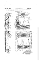
(ci. sz-129) to Figures 1 and 2, the housing of the unit com- 1 Claim.
'I'he present invention relates to air conditioning units which are adapted to be placed in or on the wall or on the floor of the room to be served, particularly small rooms wherein it is desired to filter, condition and dehumidiiy the 5 'Il-I4 on the top of the unit, each fan'having` air as it is recirculated in the room: an outlet as at I5 which extends through the top The principal object of the present invention panel I6 of the unit. A motor I1 is cushion supis to accomplish the desired results by means of ported on member I8 by means of resilient coma unit which may be manufactured and shipped position washers I8. y in a complete assembly and placed in the room 10 Motor shafts I9 extend into the housings of to be served in any desired position. fans I4 to carry on their ends fan cages 20. Thus An object of the present invention is to'proit will be seen that the rotating parts of the fan vide ia unit which will be eiiicient,4 low in cost, do not coma in contact with the fan housing, attractive and easily installed. but are cushion supported on the top ofthe main In devices of the class, when used for cooling housing thus to avoid noises being set up by the and recirculating air, the air is' dehumidiiied vibration of the motor or fan cages.
This is not easily accomplished in a simple and In Figure 1, a curvilinear arrow indicates the low priced cabinet which will not frost or sweat direction of travel or the fan cage thus the air and cause more or less larmful moisture'on the will be directed downward into the housing as inside and outside surfaces of the cabinet itself. 2o indicated by arrows.
An object of the present invention, in addition We position a filter pad on an acute angle to supplying an easily removed and replaced filter in the housing as clearly illustrated in Figure 1 pad is to provide a narrow passageway for air and provide a lid 26 which covers an opening in around the cooling` unit and between this unit' panel Ii whereby the filter pad may be conand the cabinet walls thus to prevent chilling of 25 venently removed and replaced. the cabinet walls and collection of moisture on In the bottom of panel Ii we position agrille these walls. 2l and immediately in rear of the grille we pref- A further object of the present invention is to erably position eliminators 28. Thus any mois-l provide a grilled outlet for the conditioned air ture that is released by the cooling coil will be in which may be positioned suitable eliminators. 30 trapped and drained into a drip pan 29 which is A still lfurther object of the present invention is to provide a unit which, when desired, may be placed in the wall of the room served.v
To these and other useful ends, my invention consists of parts. combinations of parts, or their equivalents. and mode of operation, as hereinafter set forth and claimed and shown in accompanying drawing in which:
Fig. 1 is a transverse sectional view of the pre-- ferred form of our invention, taken on line I--I of Figure 2.
Fig. 2is a front elevationa1 view-of the design illustrated in Figure 1, a fraction of the front panel and grille being cut-away so as to illustrate in plana fraction of the filter pad, a fraction of the cooling unit and its supporting means and a fractionfrof the elimlnators.
Fig. 3 is a fractional view of a wall illustrat ing our unit positioned therein, one oi' the fans being ysectioned transversely so as to illustrate the grille covering for the motor and fans of the device.
Fig. 4 is a frontelevatlon as illustrated in Figst ure 3. f f' @As thus mustrstea and reremng psrueuimy the prises a rear panel Ill, a front panel II and end panels I2 and I3 We position, preferably, two cage type fans positioned in the bottom of trated in Figures 1 and 2. i
We provide a cooling coil which in its entirety the cabinet as illusvis designated by reference character A comprising a number of tubes 30 which are connected at their ends by means of loops 3-I.
We provide end and side plates 35 and 36. These plates are secured together to thereby form narrow air passageways 31 around core A. The
, top and bottom edges of members 35 extend inwardly slightly and contact the upper and lower ends of members 33.' These ends in turn rest onbrackets 38 and 38' which act to maintain the air duct in a central position land prevent these members from contacting members l0, l l, I2 and I3.
Thus it will be seen that core A will be rigidly and centrally supported within the housing and that a free and isolated passageway for the warm air is provided between the core A and the cabinet walls. Without this air duct 31 the walls of the cabinet adjacent the core would sweat because of the close proximity of :the core. The present inventionis particularly adaptable for the use of water'as a cooling medium. Therefore, water connections are made to pipes 34 for the purpose and have a suitable inlet valve (not shown) for regulating thequantity of water used. Y
It will be understood that we may elect to use a. refrigerant in coil A. Furthermore, the coilv may be adapted for the useof steam or hot water for heating theJ air moved through the unit. In any event, the air passageway 31 will prevent and that any moisture removed from the air will be caught in pan 29 and that the lter may be v easily' removed and replaced;
Since the air enters the fans at the top of the cabinet and leaves th cabinet at its bottom,`
the device will be inclined to circulate al1 of the air within a reasonable distance from the cabi net.
be positioned on the oor of the room served.
In Figures 3.and 4 we illustrate our improved unit as positioned within the wall of the room served. 'I'his may be done so as to expose the front .oi' the cabinet or al1-ofthe cabinet may. be set within the wall except the two grilles 21 and 45 arid member 26. v
'In Figures 3 an'd 4 I illustrate the panel Il asbeing ilush with the wall. In view oi' the action of the air duct 31 it will be seen that the heating or cooling medium will clearly not aflect the walls of the cabinet and therefore the cabinet may be positioned in the walls as illusv trated with safety.
clearly the cabinet may be secured to the wanA in any desired position or for that matter. it may In Figure 3, numeral 4U designates a studding, numerals 4| and 42 designate the upper and lower sills, numeral 43 designates the plaster or wall board oi the adjacent room and numeral 44 designates the plaster or wall board of the room served.
It will be noted that in a narrow wall, the fans will project slightly. We preferably supply a wire screen or grille 45 which extends the full length of the cabinet as illustrated in Figure 4 thus to -shield the opening in the wall and improve the appearance of the installation.
A device of the class described, comprising ai vertically extending elongated cabinet being reclet grille in the bottom of the frontpanel of said cabinet, a core positioned' in said cabinet and above said grille and being surrounded by a relatively narrow independent air eway, said below the core, the core being; supported directly thereby, said enclosure being secured to the walls of said cabinet by means of narrow brackets the vent the ilow of moisture from said core inclosure to the cabinet walls.
Priority Applications (1)
| Application Number | Priority Date | Filing Date | Title |
|---|---|---|---|
| US294586A US2337518A (en) | 1939-09-13 | 1939-09-13 | Unit for dehumidifying, filtering, cooling, and recirculating air |
Applications Claiming Priority (1)
| Application Number | Priority Date | Filing Date | Title |
|---|---|---|---|
| US294586A US2337518A (en) | 1939-09-13 | 1939-09-13 | Unit for dehumidifying, filtering, cooling, and recirculating air |
Publications (1)
| Publication Number | Publication Date |
|---|---|
| US2337518A true US2337518A (en) | 1943-12-21 |
Family
ID=23134055
Family Applications (1)
| Application Number | Title | Priority Date | Filing Date |
|---|---|---|---|
| US294586A Expired - Lifetime US2337518A (en) | 1939-09-13 | 1939-09-13 | Unit for dehumidifying, filtering, cooling, and recirculating air |
Country Status (1)
| Country | Link |
|---|---|
| US (1) | US2337518A (en) |
Cited By (13)
| Publication number | Priority date | Publication date | Assignee | Title |
|---|---|---|---|---|
| US2438767A (en) * | 1944-07-01 | 1948-03-30 | Modine Mfg Co | Heating element and support therefor |
| US2471784A (en) * | 1945-11-19 | 1949-05-31 | Seifner | Heat exchange unit |
| US2528650A (en) * | 1949-08-18 | 1950-11-07 | Frank A Graham | Wall type electric air heater and circulator |
| US2542670A (en) * | 1946-08-21 | 1951-02-20 | Elson M Harter | Air conditioning fireplace |
| US2637532A (en) * | 1951-03-31 | 1953-05-05 | Augustus L Baker | Fan type heat exchanger |
| US2680355A (en) * | 1951-06-21 | 1954-06-08 | Colomb Gracie Hebert | Dehumidifying machine |
| US2724044A (en) * | 1953-05-29 | 1955-11-15 | St Joe Machines Inc | Electric heating and air circulating unit |
| US2771963A (en) * | 1953-12-24 | 1956-11-27 | Lennox Ind Inc | Air conditioning unit and air filter therefor |
| US3046758A (en) * | 1960-08-11 | 1962-07-31 | Olin Mathieson | Heat exchangers |
| US3461955A (en) * | 1968-03-25 | 1969-08-19 | Robert S Mckinnon | Heat exchange apparatus |
| US3523180A (en) * | 1967-02-01 | 1970-08-04 | Chester R Kennedy | Electric space heater |
| US4428207A (en) | 1981-10-09 | 1984-01-31 | Martin Industries, Inc. | Dehumidifier |
| US20050276689A1 (en) * | 2004-06-15 | 2005-12-15 | Ing-Jer Chiou | [fan module] |
-
1939
- 1939-09-13 US US294586A patent/US2337518A/en not_active Expired - Lifetime
Cited By (13)
| Publication number | Priority date | Publication date | Assignee | Title |
|---|---|---|---|---|
| US2438767A (en) * | 1944-07-01 | 1948-03-30 | Modine Mfg Co | Heating element and support therefor |
| US2471784A (en) * | 1945-11-19 | 1949-05-31 | Seifner | Heat exchange unit |
| US2542670A (en) * | 1946-08-21 | 1951-02-20 | Elson M Harter | Air conditioning fireplace |
| US2528650A (en) * | 1949-08-18 | 1950-11-07 | Frank A Graham | Wall type electric air heater and circulator |
| US2637532A (en) * | 1951-03-31 | 1953-05-05 | Augustus L Baker | Fan type heat exchanger |
| US2680355A (en) * | 1951-06-21 | 1954-06-08 | Colomb Gracie Hebert | Dehumidifying machine |
| US2724044A (en) * | 1953-05-29 | 1955-11-15 | St Joe Machines Inc | Electric heating and air circulating unit |
| US2771963A (en) * | 1953-12-24 | 1956-11-27 | Lennox Ind Inc | Air conditioning unit and air filter therefor |
| US3046758A (en) * | 1960-08-11 | 1962-07-31 | Olin Mathieson | Heat exchangers |
| US3523180A (en) * | 1967-02-01 | 1970-08-04 | Chester R Kennedy | Electric space heater |
| US3461955A (en) * | 1968-03-25 | 1969-08-19 | Robert S Mckinnon | Heat exchange apparatus |
| US4428207A (en) | 1981-10-09 | 1984-01-31 | Martin Industries, Inc. | Dehumidifier |
| US20050276689A1 (en) * | 2004-06-15 | 2005-12-15 | Ing-Jer Chiou | [fan module] |
Similar Documents
| Publication | Publication Date | Title |
|---|---|---|
| US2337518A (en) | Unit for dehumidifying, filtering, cooling, and recirculating air | |
| US2391859A (en) | Room cooling device | |
| US2116873A (en) | Self-contained air-conditioning unit | |
| US2251649A (en) | Air conditioning dehumidifier | |
| US2054200A (en) | Air conditioning apparatus | |
| US2811840A (en) | Filtered duct in refrigerator | |
| US2112221A (en) | Ventilating and air treating unit | |
| US3290866A (en) | Evaporative cooler | |
| US2932956A (en) | Air-conditioning apparatus of the induction type | |
| US3403725A (en) | Axial flow fan arrangement for fan coil unit | |
| US2680599A (en) | Evaporative condenser | |
| US1884534A (en) | Portable air-conditioning device | |
| US3110286A (en) | Forced air ventilating floor for poultry houses | |
| US2201647A (en) | Air conditioning apparatus | |
| US2053393A (en) | Means for creating uniform temperature conditions in small spaces | |
| US3147319A (en) | Evaporative cooler construction | |
| US2629587A (en) | Apparatus for conditioning air | |
| US2175758A (en) | Air conditioning apparatus | |
| US1835812A (en) | Air washer and humidifier | |
| US1984658A (en) | Air conditioning machine | |
| US2638331A (en) | Humidifier | |
| US1950347A (en) | Air washer and humidifier | |
| US1963412A (en) | Humidifier | |
| US2066817A (en) | Air conditioning, heating, and cooling units | |
| US1866650A (en) | Air treating apparatus |