US2335514A - Cigarette machine - Google Patents
Cigarette machine Download PDFInfo
- Publication number
- US2335514A US2335514A US369872A US36987240A US2335514A US 2335514 A US2335514 A US 2335514A US 369872 A US369872 A US 369872A US 36987240 A US36987240 A US 36987240A US 2335514 A US2335514 A US 2335514A
- Authority
- US
- United States
- Prior art keywords
- barrel
- tube
- tobacco
- paper
- drum
- Prior art date
- Legal status (The legal status is an assumption and is not a legal conclusion. Google has not performed a legal analysis and makes no representation as to the accuracy of the status listed.)
- Expired - Lifetime
Links
Images


Classifications
-
- A—HUMAN NECESSITIES
- A24—TOBACCO; CIGARS; CIGARETTES; SIMULATED SMOKING DEVICES; SMOKERS' REQUISITES
- A24C—MACHINES FOR MAKING CIGARS OR CIGARETTES
- A24C5/00—Making cigarettes; Making tipping materials for, or attaching filters or mouthpieces to, cigars or cigarettes
- A24C5/40—Hand-driven apparatus for making cigarettes
- A24C5/42—Pocket cigarette-fillers
Definitions
- This invention relates to a machine for making cigarettes.
- An object of the present invention is the provision of a small machine for making cigarettes.
- Another object is the provision of a machine for homeV use which is capable of making cigarettes comparable in appearance and structure to the manufactured cigarettes now on the market.
- Another object is the provision of a cigarette machine for home use which is capable of easily and rapidly making the cigarettes.
- a further object is the provision of a cigarette machine which will reduce materially the cost of cigarette smoking.
- a further object is the provision of a cigarette machine fo-r home use with which it is possible to regulate the packing of the tobacco in the cigarettes, the range extending anywhere from a loosely packed to a tightly packed cigarette.
- Yet another object is the provision of a machine for turning out perfect cigarettes made of any tobacco the operator may desire to use.
- a still further object is the provision of a machine for home use inL which pure tobacco may be used to turn out cigarettes with all the advantages as to appearance and structure of manufactured cigarettes, Without the disadvantages thereof occasioned by the addition of foreign substances to the tobacco in these latter cigarettes.
- Yet another object is the provision of a machine for producing cigarettes having the paper spirally wound therearound, thus enabling the tobacco to be packed more tightly than in the common type of cigarette.
- Still another object is the provision of a device of the character described which is neat, compact, relatively simple in construction, and which may be easily operated.
- the present invention consists essentially of a cigarette machine comprising a base, means on the base for forming a spiral tube of cigarette paper, and means for injecting tobacco into the completed tube, as more fully described in the fol# lowing specification and illustrated in the accompanying drawings, in which Figure 1 is a plan view ofthe cigarette machine with the feed hopper removed,
- Figure 2 is a side elevation of the machine
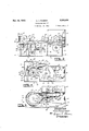
- Figure 3 is a longitudinal section taken on the line 3--3 of Figure 1,
- Figure 4 is a cross sectional view taken on the line 4-4 of Figure 1,
- Figure 5 is a cross sectional view taken on the line 5-5 of Figure 1,
- Figure 6 is a cross section taken on the line 6-6 of Figure 1,
- Figure '7 is a plan view of the feed hopper
- y Figure 8 is an elevation, partly in section, of an alternative worm feed for the machine.
- Figure 9 is an end elevation of the alternative Worm feed.
- I il is a base having a suitable end support I I with side supports I2 and I3 on each side thereof While another support I4 is spaced inwardly from the support II.
- These supports may be in the form of walls projecting upwardly from the base I0, as shown, or they may be any desired form of frame work.
- the end I 5 of the base lil will hereinafter be referred to as the feed end and the end I6 as the discharge end.
- a barrel I'I ie diameter of Which is substantially equal to that of an ordinary cigarette, projects outwardly from the support I4 adjacent the top thereof and extends longitudinally of the base towards but terminating short of the discharge end I6, the outer end of said barrel being indicated by the broken line I8 in Figure 3.
- a worm 26, preferably tapered, has an enlarged head 2l at its larger end which is journalled in a bearing 22 carried by the end support I l near the top thereof, said bearing being in line With the barrel Il.
- This Worm has a contrate gear 23 on its outer end while the opposite end of the spiral projects into the barrel I ⁇ l.r
- the worm 20 is rotated in any suitable manner and in Figure 1, the contrate gear 23 meshes on one side of the Worm with a gear 24 mounted on a stub shaft 25 which is journalled in a bearing 26 carried by the end support Il.
- the gear 24 meshes withv a gear 2lmounted on a shaftuZv extending transversely of the vmachine beneath the worm 20 and J'Ollrnalled in bearings 30 and 3i carried by the side supports I2 and I3, re-v spectively.
- the worm 20 turns inthe same direction as the crank 36is turned.
- a cover'V 3l is removably mounted on the support Il over the gear 23 in any suitable manner, suchas by being internally threaded and screwed on to a threaded collar 38 extending ar-ound said gear.
- a relatively large hopper 42 is removably mounted on the supports II, I2, I3 and I4, the sides of said hopper converging inwardly to a trough 43 extending longitudinally of the device, the bottom of which lies beneath the worm 20.
- the worm lies and operates in the trough 43 so that the worm must'be Withdrawn therefrom before the hopper may be removed.
- the hopper is shown in Figure 2, 3 and 7, but it has been removed in Figure 1 in order that the worm operating mechanism may be seen.
- the worm 2li is provided at its inner end with a light wire finger 44 (see Figure 8) which is offset from the axis of the worrn so that it rotates around said axis when the worm is rotated.
- the worm in this figure is shown with an agitator which may or may not be used in the device, as desired.
- the worm is formed with central, longitudinal passage 45 extending longitudinally thereof, through which a thin rod 46 extends and projects beyond each end thereof.
- the rod is provided with a plurality of resilient fingers or l.
- agitators 41 diverging from said rod, While the opposite end of the rod is connected to one end of a resilient arm 48, the opposite end of which is anchored in any desired manner (not shown).
- the free end of the arm 48 and, consequently the rod 46 with its agitators 41, is reciprocated by one or more cam surfaces i) located on the outer surface of the contrate gear 23.
- An agitator 5I in the form of a blunt blade, is reciprocally mounted in the hopper l2 immediately over the worm 2c at the point where it enters the barrel I1.
- This agitator extends freely through vthe wall of the hopper and is connected by a web 52 lying at right angles thereto, to a pitman arm 53 extending parallel to the agitator and slidably mounted in a bracket 54 carried by a support 55 extending from the end support II to the support I4 at one side of the worm.
- the arm 53 is provided at its outer end with a Vertical slot 56, see Figure 3, in which an eccentric pin 51 operates, said pin projecting outwardly from the gear 33, so that the rotation of this gear causes the pitman arm and the agitator to reciprocate.
- the agitator 5I is of such length that when it is in one extreme position, it clears the hopper 42 in order that the latter may be removed.
- the apparatus described thus far is adapted to feed tobacco into the barrel I1.
- the tobacco is placed in the hopper 42 over the worm in the trough 43. may be provided for pressing the tobacco do-wnwardly or the operator may press it down with his fingers.
- the crank 3S When the crank 3S is turned, the worm turns to move tobacco along the trough into the barrel This tends to pack the tobacco around the comparatively small entrance to the barrel, but the reciprocating agitator 5I assists in break- :lngv up any lump of tobacco which may start to form at said entrance.
- the tobacco forms substantially a funnel leading to the barrel and the opening in this funnel gradually grows smaller as the tobacco builds up.
- An endless belt 51 having at least one turn around the barrel I1 adjacent its outer end, extends across the machine at an angle to both the barrel and the ends of the machine.
- Suitable means is provided for drawing the belt around the barrel, such as, for example, a drum 58 positioned in line with the belt at one side of the barrel, the upper surface of the drum being substantially parallel with the upper surface of the barrel.
- This drum is xedly mounted on a shaft EQ which is journalled in a support Eil and a standard 62 spaced from the support, said support and standard being substantially parallel to the belt 51.
- a ratchetwheel 63 is flxedly mounted on the shart 6B between the support 6I and the standard 6-2.
- the drum 58 is adapted positively to grip the belt and to this end it is provided with a plurality of short pins 64 projecting outwardly from the periphery thereof which stick into the belt as it passes over the drum surface.
- the drum has a vertical flange 55 projecting outwardly from its surface at the side thereof cl-osest to the feed end I5 of the device. This flange prevents the belt from creeping along the barrel towards the end I5 of the device when the drum is rotated.
- the belt 51 passes over a suitable bearing 6G lying in substantially the same plane as the top of the barrel.
- a spring piece 51 extends downwardly from the bearing 65 and its lower or free end tends to spring outwardly so that the belt, which extends over this piece, is kept relatively taut or, in other words, the spring piece 61 takes up any slack in the belt.
- Suitable means is provided for retaining a roll 1U of relatively narrow cigarette paper which has a gummed edge 1I, said roll being held substantially parallel to the belt 51 and in line with the portion of the latter moving over the bearing 66.
- the roll rests loosely in a receptacle 12 made up of a curved strip of resilient metal 13 forming the bottom and outer end of the receptacle, and a plate I4 on one side thereof, the side of the drum 53 and its iiange 65 forming its opposite side.
- the strip of metal 'I3 extends inwardly beneath the barrel I1 where it is bent in an easy curve back o-n itself and anchored at 14 on a brace 15 extending between the supports I4 and 6I above the base i9, see Figures 2 and 5.
- a strip of paper 'I5 is drawn from the roll 10 over the metal strip 13 and then along the lower surface of a guide 1l. This guide, see Figure 5, extends from a point just above the strip 13 towards the side of the machine opposite to that on which the receptacle 12 is located, and then it is bent in a gradual curve upwardly and over beneath the belt 51 to join a table 18 over which the belt is moved, this table extending the full length of the machine, as shown in Figure 1.
- a vertical guide 19 is mounted on the table along side the belt on the side thereof closest to the feed end of the device.
- the paper follows the guide 11 and passes over the table 18 beneath the belt.
- the upper surface of the table may be slotted so that the strip of paper passes through the slot while the belt passes over the surface of the table.
- the belt presses against the paper adjacent this point and it is the movement of the belt that draws the strip of paper from the roll. As the belt progresses, it draws the strip of paper around the barrel ⁇
- the belt applies considerable pressure to the paper since the belt is drawn around the barrel.
- the angle of the belt and the paper to the barrel is'such that the gummed edge of the strip arriving at the barrel' overlaps the opposite or free edge 0'1' that portion of the strip which has already travelled around the barrel.
- Suitable means is provided for moistening the gummed edge of the paper just before it reaches the barrel
- the gummed edge may be continually moistened but it is preferably intermittently moistened in order to avoid the possibility of weakening the paper with too much moisture.
- the moistening means consists of a water reservoir 88, see Figure 5, located adjacent the strip of paper 16 and having a wick 8
- a notch 82, see Figure 1, is cut in the table 18 to enable the wick to be moved upwardly against the gummed edge of the strip of paper.
- the water reservoir is removably supported immediately beneath the table by a, substantially U-shaped spring bracket 83 the lower arm of which is attached to the reservoir at the bottom thereof, and its upper arm, longer than the lower one, slidably flts into a holder 84 mounted on the table 18.
- gripping elements 85 may project upwardly from the top and downwardly from the bottom of the bracket 83 in order to facilitate the removal of the reservoir when it is to be filled with water, there being a covered opening (not shown) formed in the reservoir for this purpose.
- a comparatively long shaft 86 extends beneath the barrel
- This shaft is journalled in a bearing 81 carried by the support
- the drum 58 is rotated in a manner to be described and draws the belt 51 and the strip of paper 16 around the barrel
- the very great pressure of the belt against the paper on the barrel presses the moistened gummed edge of the paper lying therebeneath during at least one turn around the barrel.
- the drum 58 may be rotated in any suitable manner and this rotation is preferably intermittent.
- the means for rotating the drum is shown in conjunction with means for controlling the pressure of the tobacco in the tube 93.
- a clutch disc 94 is fixedly mounted on the shaft 86 beyond the support 6
- This clutch disc consists of spaced discs 95, best seen in Figure 2, having one or more eccentric pins 96, in this case two, extending therebetween equispaced from each other and from the shaft 86.
- An arcuate control arm 91 extends upwardly over and clear of the barrel
- This arm has a downwardly extending radial arm 98 at its inner end, which is freely mounted on the shaft 68 between the support 6
- 88 is mounted on the outer end of the control arm 91 and points inwardly and upwardly towards the clutch disc.
- extends outwardly from the inner end of the tube
- 82 extends from the arm 91 into the outer end of the tube
- 83 is pivotally mounted on the control arm 91 at the radial arm 98, said pawl being adapted to engage the teeth of the ratchet-wheel 63 to turn said wheel 63 to the left in Figure 4 when the outer end of the control arm 91 is raised upwardly, and to move over a deector shelf
- 85 extending upwardly from the base I8, engages the teeth of the ratchet-wheel in order to prevent it from being turned to the right in Figure 4.
- 86 is mounted on the control arm 91 between the ends thereof.
- This nger gauge consists of a vertical rod
- 86 is bent at its upper end over and along the upper edge of the control arm to form a horizontal rod l
- the rod I8 is normally spaced above the control arm but the'horizontal rod is bent downwardly towards the arm until its opposite end touches the control arm where it is connected thereto in any suitable manner.
- the upper edge of the control arm is curved, the natural tendency of the free end of the horizontal rod is to remain above the arm.
- the position of the finger gauge in relation to the control arm may be adjusted by moving the slide arm back andforth over the rod
- 86 rests on the filled spiral tube's3 and holds up the outer end of the control arm '31.
- the control arm is held in such a position that the tip of the pin IBI lies in the path of the pins 955 of the clutch disc Si.
- a pin Q5 cornes around, it engages the tip ⁇ of the pin IIJI and begins to move the latter pin and the outer end of the control arm upwardly.
- the pin 55 continues along its circular course, it rst .moves along the pin ISI Vtowards the control arm, thus magnifying the engagement of the two pins to ensure a positive grip therebetween.
- the pin 96 As the pin 96 further continues its course, it recedes from the control arm and nally disengages the pin I DI to permit the control arm to drop downwardly until the next pin 96 engages .the pin IUI. .
- the ratchet-wheel 53 remains stationary while the pawl Iii moves off the deflector shelf its but during the latter part of said movement, the pawl engages the teeth of the ratchet-wheel to turn the latter, which, in turn, rotates the drum 52.
- the Enger gauge When the pressure of the tobacco in the tube 93 is not suncient, the Enger gauge It presses the wall of the tube downwardly, thus permitting the control arrn to drop downwardly to move the pin IIlI out of the path of the pins 9%. This condition remains until the pressure of the tobacco in the tube is great enough to raise the nger gauge and the control arm upwardly to return the pin II into the path of the iingers B6.
- the ratchet-wheel 23 and the drum 58 remain stationary when. the pressure of the tobacco in the tube 93 is below a predetermined point.
- the desired pressure of this tobacco may be regulated by moving the slide II I along the control arm to raise or lower the linger gauge in relation to said arm, the lower said gauge is the lower the pressure required in the tube 93 to set the drum 58 into motion and vice versa,
- a frame IIS supported at one side above the base by a post II4 and at the other side by a web
- the frame I I3 consists of spaced plates I l5 between which a knife III is pivotally mounted.
- a short tube IIS extends inwardly from the frame
- 22 is formed in the outer plate M6 in line with the tube IIS, the diameter of this opening of said tube where itv joins the frame is only slightly larger than that of an ordinary cigarette.
- the knife II'I consists of a substantially rectangular holder I2 I, see Figures l and 6, pivotally mounted at its upper and outer corner upon a pivot pin
- a blade I 23 is removably held by the holder
- 24 is loosely journalled at its lower end in a long vertical bearing
- this connecting rod is bent over to form a finger
- 21 see Figure 6, is anchored at one end of the frame IIS, atIZS, on the inner surface thereof and extends across the frame beneath the nger
- is cut away to form a recess I il!! adjacent the connecting rod
- the anvil projects outwardly from the rod and extends through the recess
- 34 is pivotally mounted at its upper end at the upper edge of the support 6
- 38 extends outwardly and downwardly trom the upper end of the arm
- An arcuate lever Mll extends outwardly and downwardly irom the end of the control arm 91 adjacent the drum 5s and this arm normally passes over and down beside the anvil
- 31 moves the free or lower end of the arm
- the lever lili) has been moved down past the anvil and it is at this time that the arm
- 42 is mounted on the base It and as this surface lies in the path of the anvil ISI when it is moved downwardly, the surface causes the anvil to pivot back. to its normal position, this being possible since the cam
- the finger 44 on the end of the Worm rotates in the tobacco within the barrel to prevent said tobacco from packing too solidly or in lumps by stirring it up before entering the tube.
- the rod 46 is reciprocated in the worm and consequently the resilient lingers or agitators 41 are also reciprocated.
- the agitators 41 are drawn towards the worm, the pressure of the tobacco causes them to collapse together so that they offer very little resistance to the movement of the tobacco, but when the agitators are moved away from the worm, their free ends spread outwardly and press the tobacco on through the barrel
- These agitators reach the tobacco near the walls of the barrel so that it is moved along with that at the centre of the barrel, said latter tobacco being moved by the worm.
- the turning of the crank 36 also rotates the clutch disc 04 which, when the pressure of the tobacco in the cigarette reaches a predetermined point,vraises the free end of the control arm 91 to cause said arm to rotate the drum 58.
- This drum draws the belt 51 and consequently the strip of paper 16 around the barrel I1 to form the spiral tube 93.
- This tube fills with tobacco and moves on into the tube
- 1 is operated to cut off a desired length of cigarette.
- 23 causes the latter to move both downwardly and across the filled tube 93 which results in a nice clean cut.
- is moved out of its normal position when the drum 58 is in motion. This means that the anvil assumes a position in the path of the lever
- the drum 58 remains stationary if the tobacco in the spiral tube is not packed tight enough. This is due to the fact that the finger gauge
- of the water reservoir 80 moistens the gummed edge of the strip of paper 16 as it passes thereover.
- the setting of the cam 92 is such that the wick is held away from the paper when the crank 36 is at rest in a vertical position, as this is the position the crank is naturally left in when the operator is through with the machine. This prevents the paper from becoming too moist when the machine is at rest.
- This machine is so designed that one rotation of the drum 58 moves the tube 93 forwardly a distance equal to the length of a conventional cigarette. This distance of movement is dependent upon the size of the drum, the width of the paper, and the angle at which the belt 51 is set in relation to the barrel
- crank 36 While a crank 36 has been shown, it is to be understood that a small motor may be connected to the shaft 34 so that the machine would be power driven. This device is primarily designed for home use but, if desired, it may be built any required size for commercial usage.
- the cigarettes turned out by this machine are evenly packed and they have the appearance and structure equal to that of commercially manufactured cigarettes.
- the spiral winding of the tube 93 permits tobacco to be injected thereinto under pressure without bursting open the seams. This is due to the fact that lateral pressure does not press against any seam which would be the case with ordinary cigarettes having one longitudinal seam.
- This machine turns out cigarettes in an easy and rapid manner. It reduces the cost of smoking since it gives the smoker all the advantages of a hand rolled cigarette together with the appearance and structure of a manufactured cigarette. This means that many people will be able to make their own cigarettes who could not roll their own or who were unable to make a decent looking cigarette on their own.
- This machine may be set to produce a fairly loosely packed cigarette or anything up to a tightly packed one, in accordance with the operators desire and any type of tobacco may be used therein. When pure tobacco is used, the cigarettes produced do not include the foreign substances which are intro quizd into manufactured cigarettes. Finally, this machine is neat, compact, relatively simple in construction and it may be very easily operated.
- a cigarette machine comprising a base, a barrel supported above the base, the diameter of said barrel being substantially equal to that of a cigarette, an endless belt having at least one turn around the barrel, means for holding a strip of narrow gummed cigarette paper in the machine, means for moistening the gummed edge of the paper, said paper extending around the barrel at least one complete turn with its gummed edge overlapping the free edge thereof beneath the belt, means for intermittently drawing the belt around the barrel to move the paper therearound under pressure to form a spiral tube, said tube being moved off the barrel, and means for injecting tobacco into the tube during both the moving and stationary periods of the belt.
- a cigarette machine comprising a base, a barrel supported above the base, the diameterof said barrel being substantially equal to that of a cigarette, an endless belt having at least one turn around the barrel, means for holding a strip of narrow gurnmed cigarette paper in the machine, means for moistenng the gummed edge ofthe paper, said paper extending around the barrel at least one complete turn with its gummed edge overlapping the free edge thereof beneath the belt, a drum at one side of the barrel, over which the belt extends, means for intermittently rotating the drum to draw the belt around the barrel to move the paper therearound under pressure to form a spiral tube, said tube being moved o the barrel, and means for injecting tobacco through the barrel into the tube during both the moving and stationary periods of the belt.
- a cigarette machine comprising a base, a barrel supported above the base, the diameter of said barrel being substantially equal to that of a cigarette, an endless belt having at least one turn around Vthe barrel, means for holding a strip of narrow gummed cigarette paper in the machine, means for moistening the gummed edge of the paper, said paper extending around the barrel at least one complete turn with its gummed edge overlapping the free edge thereof beneath ⁇ the belt, a drum at one side of the barrel, a bearing at the other side of the barrel, said belt extending around the drum and the bearing, means o n the drum for positively gripping the belt, means for intermittently rotating the drum to draw the belt around the barrel to move the paper therearound under pressure to form a spiral tube, means for injecting tobacco through the barrel into the tube, and means for cutting the lled tube into desired lengths, said cutting means operating when the drum is at rest.
- a cigarette machine comprising a base, means on the base for holding a strip of narrow gummed cigarette paper, means for forming said paper into a continuous tube and intermittently moving said tube forwardly in the machine, means for injecting tobacco into the tube during both the moving and stationary periodsof the tube, a iinger gauge connected to theY moving means and ladapted to bear against the iilled tube, said gauge causing the moving means to operate when the pressure of the tobacco in the tube reaches a predetermined point and preventing said operation when the pressure drops below said point.
- a device in which the means for intermittently rotating the drum comprises a ratchet-wheel connected to the drum, a pawl adapted to engage theratchet-Wheehand means for reciprocatingr the pawl intermittently to rotate the ratchet-Wheel and the drum.
- a device in which the means for intermittently rotating the drum lcomprises a control arm pivotally mounted at one end thereof on the base, a ratchet-Wheel connected to the drum, a pawl mounted on the control arm adjacent its pivotsaid pawl being adapted to engage the ratchet-wheel, a clutch disc supported adjacent the free end of the control arm, means for rotating the clutch disc, and means on the clutch disc for intermittently raising andreleasing the free end of the control arm to pivot said arm intermittently to rotate the ratchet-wheel and the drum.
- the means for intermittently rotating ythe drum comprises a control arm pivotally mounted at one end thereof f on the lbase, a ratchet-wheel connected to the erom, a patti mounted on theooiitroiafm adjacentl its pivot, said pawl being adapted to engage the ratchet-Wheel, a clutch disc supported adjacent the free end of the control arm, means forrotating the clutch disc, :at least one prin eccentrically mounted on the clutch disc, and apin mounted on the free end of the control arm 'no'rg mally projecting into vthe path of the eccentric pin, said Clutch pin intermittently engaging tijd lpin Of the Control arni to raise theflee 'end there',- of to pivot said ont intermittently to rotate trie ratchet-wheel and the drum.
- a device in which the means for intermittently rotating the drun corn-l prises a control armmounted at one end thereof on the base, a ratchet-Wheel connected to the drum, a pai/vl mounted Oh the Control aIhl adjacent its pivot, said pawl being adaptedt engage the ratchet-Wheel, a clutchV adjacent the free end of the control arm for intermittently raising said end, and a linger gauge mounted 'n the control arm adapted to rest on thfejilled spiral tube, said gauge causing the control arm end to engage the clutch when the pressure of the tobacco in the tube reaches' a predetermined point to raise said eno and to disenga'ge the crutch when the pressure drops belovv ⁇ said point.
- a device in iivhich the means for intermittently rotating the drum come prises a 'control arm nivo-tally Arnou'nted at 'one end thereof onthe base, a ratchet-Wheel c'nnecte'd to the drum, 'a pawl mounted on tlev'co'r'ftrol arm adjacent itsv pivot, said paivl being adapted to "engage the ratchet-Wheel, a clutch disc supported adjacent the 'free end of the 'con trol arm, means for rotating the clutch-disc, at least one pin eccentrically mounted on the clutch disc, a pin mounted 'on the free endof the control jarro extending towards the 'clutch disc, and a linger gauge mounted on lthe control arm adopted to' rest on 'tao nii-ed spiral tub-e, ssijo gauge retaining the control jar'rn in a position With its pinprojecti'ng
- a cigarette machine y.comprising a base, means for moistening the gummed edgeof acontinuous strip oi cigarette paper, means ior forme ing a continuousy spiral tube from the "paper 'and intermittently moving said tube forwardly in the machine, means for injecting tobacco into the tube, a lrnife normally resting adjacentjthe lled tube, andA meansfor moving the blade' of said knifethrough the filled tube at predetermined intervals when the tube is stationary to cut said tube into desired lengths.
- a device including :a drum over Whichvthe belt extends, means flor intermittently rotating ytrie drum to draw the belt and paper around* the barrel, a knife nor,- mally resting adjacent the iilled'tulflye, ⁇ and means operated by the drum rotating means formovig the blade oi said rlcniie through the filled tubea't predetermined interi/on when the tube is stationary to'cut said tube into desired lengths.
- a device Aaccor'd'inig to claim 2 including'a ratchet connected to the drum, a control arm pivotally mounted at one :end adjacent the ratchet, means for reciprocating the arm to operate the ratchet and rotaterthe drumto'dravvtlfe belt and paper around the barrel, a lever mounted on the control arm, anwanvil pvotally mounted near the lever, 'a knife normally resting/,adjacent the lled tube, said knife being connected totheI anvil, a cam mounted on the drum. and means operatedby the cam for moving the anvil into the path of the lever, said lever moving the anvil to move the blade of the knife through the lled tube at predetermined intervals to cut said tube into desired lengths.
- Al cigarette machine comprising a base, means for holding a strip of narrow cigarette paper, said paper being gummed valong an edge thereof, means forforming a continuous spiral tube from the paper, a water reservoir movably mounted on the base adjacent the strip of paper, a wick projecting outwardly from the reservoir, means for intermittently moving the reservoir towards the paper to bring the Wick into contact with the gummed edge thereof before it is formed into the spiral tube, and means for injecting tobacco into the tube.
- a cigarette machine comprising a base, a barrel supported above the base, the diameter of said barrel being substantially equal to that of the cigarette, means for forming a tube of cigarette paper around the barrel and discharging said tube off one end thereof, a hopper mounted on the base adapted to receive tobacco, a trough formed in the bottom of the hopper and communicating with the opposite end of the barrel, a tapered worm mounted in the trough with its smaller end extending into the barrel, means for rotating the Worm to inject tobacco through the barrel into the tube, a central longitudinal passage extending through the worm, a rod extending through said passage beyond each end thereof, a plurality of resilient agitators diverging from the inner end of the rod, and means at the outer end of the rod for reciprocating the latter as the worm is rotated.
- a cigarette machine comprising a base, a barrel supported above the base, the diameter of said barrel being substantially equal to that of a cigarette, means for forming a tube of cigarette paper around the barrel and discharging said Itube off one end thereof, a hopper communicating with the opposite end of the barrel, said hopper being adapted to receive tobacco, a worm mounted in the bottom of the hopper and extending into the barrel, means for rotating the Worm to inject tobacco through the barrel into the tube, an agitator extending into the hopper through one end thereof adjacent the Worm at the barrel entrance, and means for reciprocating the agitator in the hopper in a direction parallel to the axis of the worm to prevent tobacco from jamming in the barrel entrance.
- the means for intermittently rotating the drum comprises a control arm mounted at one end thereof on the base, a ratchet-Wheel connected to the drum, a pawl mounted on the control arm adjacent its pivot, said pawl being adapted to engage the ratchet-wheel, a clutch adjacent the free end of the control arm for intermittently raising said end, a finger gauge mounted on the control arm adapted to rest on the lled spiral tube, and means for adjusting the position of the finger gauge in relation to the control arm, said gauge causing the control arm end to engage the clutch when the pressure of the tobacco in the tube reaches a predetermined point to raise said end and to disengage the clutch when the pressure drops below said point.
- a cigarette machine comprising a base, a barrel supported above the base, the diameter of said barrel being substantially equal to that of a cigarette, an endless belt having at least one turn around the barrel, means for holding a strip of narrow cigarette paper in the machine, said paper being gummed along an edge thereof, a Water reservoir movably mounted on the base adjacent the strip of paper, a wick projecting outwardly from the reservoir, means for intermittently moving the reservoir towards the paper to bring the wick into contact with the gummed edge thereof, said paper extending around the barrel at least one complete turn beneath the belt with its gummed edge overlapping the free edge thereof beneath the belt, a drum at one side of the barrel over Which the belt extends, means for intermittently rotating .the drum to draw the belt around the barrel to move the paper therearound under pressure to form a spiral tube, said tube being moved off the barrel, and means for injecting tobacco through the barrel into the tube.
- a cigarette machine comprising a base, a barrel supported above the base, the diameter of said barrel being substantially equal to that of a cigarette, means on the base for moistening the gummed edge of a narrow continuous strip of cigarette paper, means for forming a continuous spiral tube from the paper around the barrel, means for intermittently moving the tube off the barrel, means for injecting tobacco into the tube, a knife normally resting adjacent the filled tube, and means for moving the knife through the filled ⁇ tube at predetermined intervals when said tube is stationary.
- a cigarette machine comprising a base, a barrel supported above the base, the diameter of said barrel being substantially equal to that of a cigarette, an endless belt. having at least one turn around the barrel, means for holding a strip of narrow gummed cigarette paper in the machine, means for moistening the gummed edge of the paper, said paper extending around the barrel at least one complete turn with its gummed edge overlapping the free edge thereof beneath the belt, a drum at one side of the barrel over which the belt extends, means for intermittently rotating the drum to draw the belt around the barrel to move the paper therearound under pressure to form a spiral tube, said tube being intermittently moved off the barrel, means for injecting tobacco into the tube, a knife normally resting adjacent the lled tube, and means for moving the knife through the lled tube at predetermined intervals when said tube is stationary.
- a cigarette machine comprising a base, a barrel supported above the base, the diameter of said barrel being substantially equal to that, of a cigarette, an endless belt having at least one turn around the barrel, means for holding a. strip of narrow gummed cigarette paper in the machine, means for moistening the gummed edge of the paper, said paper extending around the barrel at least one complete turn with its gummed edge overlapping the free edge thereof beneath the belt, means for intermittently drawing the belt around the barrel to move the paper therearound under pressure to form a spiral tube, said tube being moved off one end of the barrel, a hopper communicating with the opposite end of the barrel, said hopper being adapted to receive tobacco, a worm mounted in the bottom of the hopper and extending into the barrel, means for rotating the worm t0 inject tobacco through the barrel into the tube, an agitator extending into the hopper adjacent the worm at the barrel entrance, and means for reciprocating the agitator in the hopper to prevent tobacco from jamming in the barrel entrance.
- a cigarette machine comprising a base, a barrel supported above the base, the diameter of said 'barrel being substantially equal to that of a, cigarette, an endless belt having at least one turn around the barrel, means for holding a strip .of narrow gummed cigarette paper in the machine, means for moistening the .gummed edge of the paper, said paper extending around the barrel at least one complete turn With its gummed edge overlapping the free edge thereof beneath the belt, means for drawing the belt around the barrel to move the paper vtherearound under pressure to form :a spiral tube, said tube .being moved 01T one end of the barrel, .a hopper communicating with the opposite end ofthe barrel,.said hopper .being kadapted to receive tobacco, a worm mounted in the bottom Aof the hoppervand extending into the barrel, means for rotating th'eworm to inject tobacco through the barrel into the tube: a )central longitudinal passage extending through the worm, a rod vextending through :said passage beyond each end thereof,
Description
Nov. 30, 1943. E. R. Hur-:BERT
CIGARETTE MACHINE 5 sheets-sheet i Filed Dec. 12, 1940 m WM Th www EU V K Nw im ATTORNEY Nov. 30, 1943.
E. R. HlEBl-:RT
CIGARETTE MACHINE Fild Deo. 12, 1940 5 Sheets-Sheet 2 y l B M L?. N d E@ V m mm M..
rl l
ATTORNEY Nov. 30, 1943. l E. R. HIEBERT 2,335,514
CIGARETTE MACHINE Filed DeO. l2, 1940 3 Sheets-Sheet 5 /23 /Z/ (Iza l, f 27 /257 -Y "1i/L [1 Yew E N V E N TO R fra/man udo/p/v //berf NYT@ R N EY Patented Nov. 30, 1943 UNITED CIGARETTE MACHINE Erdman Rudolph Hiebert, Sardis, British Columbia, Canada Application December 12, 1940, Serial No. 369,872
21 Claims.
This invention relates to a machine for making cigarettes.
An object of the present invention is the provision of a small machine for making cigarettes.
Another object is the provision of a machine for homeV use which is capable of making cigarettes comparable in appearance and structure to the manufactured cigarettes now on the market.
Another object is the provision of a cigarette machine for home use which is capable of easily and rapidly making the cigarettes.
A further object is the provision of a cigarette machine which will reduce materially the cost of cigarette smoking. Y
A further object is the provision of a cigarette machine fo-r home use with which it is possible to regulate the packing of the tobacco in the cigarettes, the range extending anywhere from a loosely packed to a tightly packed cigarette.
Yet another object is the provision of a machine for turning out perfect cigarettes made of any tobacco the operator may desire to use.
A still further object is the provision of a machine for home use inL which pure tobacco may be used to turn out cigarettes with all the advantages as to appearance and structure of manufactured cigarettes, Without the disadvantages thereof occasioned by the addition of foreign substances to the tobacco in these latter cigarettes.
Yet another object is the provision of a machine for producing cigarettes having the paper spirally wound therearound, thus enabling the tobacco to be packed more tightly than in the common type of cigarette. f
Still another object is the provision of a device of the character described which is neat, compact, relatively simple in construction, and which may be easily operated.
With these and other objects in view, the present invention consists essentially of a cigarette machine comprising a base, means on the base for forming a spiral tube of cigarette paper, and means for injecting tobacco into the completed tube, as more fully described in the fol# lowing specification and illustrated in the accompanying drawings, in which Figure 1 is a plan view ofthe cigarette machine with the feed hopper removed,
Figure 2 is a side elevation of the machine,
Figure 3 is a longitudinal section taken on the line 3--3 of Figure 1,
Figure 4 is a cross sectional view taken on the line 4-4 of Figure 1,
Figure 5 is a cross sectional view taken on the line 5-5 of Figure 1,
Figure 6 is a cross section taken on the line 6-6 of Figure 1,
Figure '7 is a plan view of the feed hopper,
yFigure 8 is an elevation, partly in section, of an alternative worm feed for the machine, and
Figure 9 is an end elevation of the alternative Worm feed.
Referring more particularly to the drawings, I il is a base having a suitable end support I I with side supports I2 and I3 on each side thereof While another support I4 is spaced inwardly from the support II. These supports may be in the form of walls projecting upwardly from the base I0, as shown, or they may be any desired form of frame work. For the sake of convenience, the end I 5 of the base lil will hereinafter be referred to as the feed end and the end I6 as the discharge end.
A barrel I'I, ie diameter of Which is substantially equal to that of an ordinary cigarette, projects outwardly from the support I4 adjacent the top thereof and extends longitudinally of the base towards but terminating short of the discharge end I6, the outer end of said barrel being indicated by the broken line I8 in Figure 3. A worm 26, preferably tapered, has an enlarged head 2l at its larger end which is journalled in a bearing 22 carried by the end support I l near the top thereof, said bearing being in line With the barrel Il. This Worm has a contrate gear 23 on its outer end while the opposite end of the spiral projects into the barrel I`l.r
The worm 20 is rotated in any suitable manner and in Figure 1, the contrate gear 23 meshes on one side of the Worm with a gear 24 mounted on a stub shaft 25 which is journalled in a bearing 26 carried by the end support Il. The gear 24 meshes withv a gear 2lmounted on a shaftuZv extending transversely of the vmachine beneath the worm 20 and J'Ollrnalled in bearings 30 and 3i carried by the side supports I2 and I3, re-v spectively. Another gear 32 mounted on the shaft Non the opposite side of the worm, meshes with a gear 33 mounted on a shaft 34 mounted in a bearing 35 carried by the end support II, said shaft extending freely through the side support i2 and having a crank 36 on its outer end. With this arrangement', the worm 20 turns inthe same direction as the crank 36is turned. A cover'V 3l is removably mounted on the support Il over the gear 23 in any suitable manner, suchas by being internally threaded and screwed on to a threaded collar 38 extending ar-ound said gear.
A relatively large hopper 42 is removably mounted on the supports II, I2, I3 and I4, the sides of said hopper converging inwardly to a trough 43 extending longitudinally of the device, the bottom of which lies beneath the worm 20. Actually, the worm lies and operates in the trough 43 so that the worm must'be Withdrawn therefrom before the hopper may be removed. The hopper is shown in Figure 2, 3 and 7, but it has been removed in Figure 1 in order that the worm operating mechanism may be seen.
The worm 2li is provided at its inner end with a light wire finger 44 (see Figure 8) which is offset from the axis of the worrn so that it rotates around said axis when the worm is rotated. The worm in this figure is shown with an agitator which may or may not be used in the device, as desired. In this alternative, the worm is formed with central, longitudinal passage 45 extending longitudinally thereof, through which a thin rod 46 extends and projects beyond each end thereof. At the inner or smaller end of the'worm, the rod is provided with a plurality of resilient fingers or l.
agitators 41 diverging from said rod, While the opposite end of the rod is connected to one end of a resilient arm 48, the opposite end of which is anchored in any desired manner (not shown). The free end of the arm 48 and, consequently the rod 46 with its agitators 41, is reciprocated by one or more cam surfaces i) located on the outer surface of the contrate gear 23.
An agitator 5I, in the form of a blunt blade, is reciprocally mounted in the hopper l2 immediately over the worm 2c at the point where it enters the barrel I1. This agitator extends freely through vthe wall of the hopper and is connected by a web 52 lying at right angles thereto, to a pitman arm 53 extending parallel to the agitator and slidably mounted in a bracket 54 carried by a support 55 extending from the end support II to the support I4 at one side of the worm. The arm 53 is provided at its outer end with a Vertical slot 56, see Figure 3, in which an eccentric pin 51 operates, said pin projecting outwardly from the gear 33, so that the rotation of this gear causes the pitman arm and the agitator to reciprocate. The agitator 5I is of such length that when it is in one extreme position, it clears the hopper 42 in order that the latter may be removed.
The apparatus described thus far is adapted to feed tobacco into the barrel I1. To this end, the tobacco is placed in the hopper 42 over the worm in the trough 43. may be provided for pressing the tobacco do-wnwardly or the operator may press it down with his fingers. When the crank 3S is turned, the worm turns to move tobacco along the trough into the barrel This tends to pack the tobacco around the comparatively small entrance to the barrel, but the reciprocating agitator 5I assists in break- :lngv up any lump of tobacco which may start to form at said entrance. As the worm continues to work, the tobacco forms substantially a funnel leading to the barrel and the opening in this funnel gradually grows smaller as the tobacco builds up. As the mass of tobacco consists of numerous interwoven strings of tobacco, the turning movement of the worm tends to stretch the strings at one point when the tobacco starts to become a lump at the barrel entrance and nally these stretched strings break suddenly, releasing a mass of tobacco which flies upwardly a little way in the hopper. In other words, the
Suitable means, not shown,
tobacco seems to build up at the barrel entrance into a somewhat solid mass but the greater part of the mass is hurled away therefrom as described, thus continually freeing the entrance to permit more tobacco to move therethrough.
An endless belt 51, see Figures 1 and 5, having at least one turn around the barrel I1 adjacent its outer end, extends across the machine at an angle to both the barrel and the ends of the machine. Suitable means is provided for drawing the belt around the barrel, such as, for example, a drum 58 positioned in line with the belt at one side of the barrel, the upper surface of the drum being substantially parallel with the upper surface of the barrel. This drum is xedly mounted on a shaft EQ which is journalled in a support Eil and a standard 62 spaced from the support, said support and standard being substantially parallel to the belt 51. A ratchetwheel 63 is flxedly mounted on the shart 6B between the support 6I and the standard 6-2. The drum 58 is adapted positively to grip the belt and to this end it is provided with a plurality of short pins 64 projecting outwardly from the periphery thereof which stick into the belt as it passes over the drum surface. The drum has a vertical flange 55 projecting outwardly from its surface at the side thereof cl-osest to the feed end I5 of the device. This flange prevents the belt from creeping along the barrel towards the end I5 of the device when the drum is rotated.
At the opposite side of the barrel I1, the belt 51 passes over a suitable bearing 6G lying in substantially the same plane as the top of the barrel. A spring piece 51 extends downwardly from the bearing 65 and its lower or free end tends to spring outwardly so that the belt, which extends over this piece, is kept relatively taut or, in other words, the spring piece 61 takes up any slack in the belt.
As the upper part of the belt 51 on one side of the barrel is not in line with that on the other side thereof, owing to the twist or snub about the barrel, it is necessary to have two spaced vertical pins 63, see Figures 2 and 5, extending upwardly from the base I0, one being in line with the drum 53 and the other in line with the bearing 66 and the spring piece 61. In travelling from the drum to the lower end of the spring piece, the belt moves around one side of the pin in line with the drum and around the opposite side of the other pin.
Suitable means is provided for retaining a roll 1U of relatively narrow cigarette paper which has a gummed edge 1I, said roll being held substantially parallel to the belt 51 and in line with the portion of the latter moving over the bearing 66. In the drawings, the roll rests loosely in a receptacle 12 made up of a curved strip of resilient metal 13 forming the bottom and outer end of the receptacle, and a plate I4 on one side thereof, the side of the drum 53 and its iiange 65 forming its opposite side. The strip of metal 'I3 extends inwardly beneath the barrel I1 where it is bent in an easy curve back o-n itself and anchored at 14 on a brace 15 extending between the supports I4 and 6I above the base i9, see Figures 2 and 5. A strip of paper 'I5 is drawn from the roll 10 over the metal strip 13 and then along the lower surface of a guide 1l. This guide, see Figure 5, extends from a point just above the strip 13 towards the side of the machine opposite to that on which the receptacle 12 is located, and then it is bent in a gradual curve upwardly and over beneath the belt 51 to join a table 18 over which the belt is moved, this table extending the full length of the machine, as shown in Figure 1. A vertical guide 19 is mounted on the table along side the belt on the side thereof closest to the feed end of the device. The paper follows the guide 11 and passes over the table 18 beneath the belt. If desired, the upper surface of the table may be slotted so that the strip of paper passes through the slot while the belt passes over the surface of the table. The belt presses against the paper adjacent this point and it is the movement of the belt that draws the strip of paper from the roll. As the belt progresses, it draws the strip of paper around the barrel `|1 in a spiral, the paper making at least one complete turn around said barrel. The belt applies considerable pressure to the paper since the belt is drawn around the barrel. The angle of the belt and the paper to the barrel is'such that the gummed edge of the strip arriving at the barrel' overlaps the opposite or free edge 0'1' that portion of the strip which has already travelled around the barrel.
Suitable means is provided for moistening the gummed edge of the paper just before it reaches the barrel |1. The gummed edge may be continually moistened but it is preferably intermittently moistened in order to avoid the possibility of weakening the paper with too much moisture. In the illustrated form of the invention, the moistening means consists of a water reservoir 88, see Figure 5, located adjacent the strip of paper 16 and having a wick 8| projecting upwardly therefrom. A notch 82, see Figure 1, is cut in the table 18 to enable the wick to be moved upwardly against the gummed edge of the strip of paper. The water reservoir is removably supported immediately beneath the table by a, substantially U-shaped spring bracket 83 the lower arm of which is attached to the reservoir at the bottom thereof, and its upper arm, longer than the lower one, slidably flts into a holder 84 mounted on the table 18. If desired, gripping elements 85 may project upwardly from the top and downwardly from the bottom of the bracket 83 in order to facilitate the removal of the reservoir when it is to be filled with water, there being a covered opening (not shown) formed in the reservoir for this purpose.
A comparatively long shaft 86 extends beneath the barrel |1 at approximately right angles to the belt 51. This shaft is journalled in a bearing 81 carried by the support |4 and has a bevel gear 88 at one end meshing with another bevel gear 98 iixedly mounted on the shaft 28,
see Figure 1, while the opposite end of the shaft 86 extends through a bearing in the support 6|. A spring finger 9| extends downwardly and inwardly from the reservoir 80 adjacent its outer end, over the shaft 86, and a cam 92 mounted on said shaft,is adapted intermittently to urge the spring finger 9|, and consequently, the free end of the reservoir upwardly. This moves the Wick 8| upwardly into contact with the gummed edge of the strip of paper 16, the resiliency of the finger 9| preventing the wick from striking the paper too hard.
The drum 58 is rotated in a manner to be described and draws the belt 51 and the strip of paper 16 around the barrel |1. The very great pressure of the belt against the paper on the barrel presses the moistened gummed edge of the paper lying therebeneath during at least one turn around the barrel. This forms a continual spirally-wound tube 93 of cigarette paper, hereinafter called a spiral tube, which is moved off ZJI the end of the barrel by the new paper being continually fed thereto. The tobacco which is moved into the barrel, as previously described, passes therethrough and is injected into the spiral tube 93-as it is formed.
The drum 58 may be rotated in any suitable manner and this rotation is preferably intermittent. The means for rotating the drum is shown in conjunction with means for controlling the pressure of the tobacco in the tube 93.
A clutch disc 94 is fixedly mounted on the shaft 86 beyond the support 6| and in the plane of rotation of the ratchet-wheel 63, see Figure 4. This clutch disc consists of spaced discs 95, best seen in Figure 2, having one or more eccentric pins 96, in this case two, extending therebetween equispaced from each other and from the shaft 86. An arcuate control arm 91 extends upwardly over and clear of the barrel |'1 at substantially the same angle thereto as the belt 51. This arm has a downwardly extending radial arm 98 at its inner end, which is freely mounted on the shaft 68 between the support 6| and the ratchet-wheel 63, and at its opposite end the control arm curves over and around the outer edge of the clutch disc 94 but it is spaced from said edge and terminates adjacent the bottom of the disc. A slightly tapered tube |88 is mounted on the outer end of the control arm 91 and points inwardly and upwardly towards the clutch disc. A pointed pin |l|| extends outwardly from the inner end of the tube |88 into the space between the discs 95 and terminates at a point adjacent the bottom of the circular path of the pins 96. A curved spring |82 extends from the arm 91 into the outer end of the tube |88 to press the pin |8| into its extreme outermost position. A pawl |83 is pivotally mounted on the control arm 91 at the radial arm 98, said pawl being adapted to engage the teeth of the ratchet-wheel 63 to turn said wheel 63 to the left in Figure 4 when the outer end of the control arm 91 is raised upwardly, and to move over a deector shelf |84 projecting outwardly from the support 6| over the ratchet-wheel, when the outer end of the control arm is dropped downwardly. Another pawl |85 extending upwardly from the base I8, engages the teeth of the ratchet-wheel in order to prevent it from being turned to the right in Figure 4.
A finger gauge |86 is mounted on the control arm 91 between the ends thereof. This nger gauge consists of a vertical rod |01 having a head |08 at its lower end. The rod |86 is bent at its upper end over and along the upper edge of the control arm to form a horizontal rod l |51. Just as the rod |81, the rod I8 is normally spaced above the control arm but the'horizontal rod is bent downwardly towards the arm until its opposite end touches the control arm where it is connected thereto in any suitable manner. As the upper edge of the control arm is curved, the natural tendency of the free end of the horizontal rod is to remain above the arm. A slide operating on tracks ||2 on each side of the control arm at the upper edge thereof, lies over the control rod ||8 and when this slide is moved towards the free end of the horizontal rod, the latter is drawn or bent downwardly and, consequently, the vertical rod |81 and its head |08 are moved downwardly. In other words, the position of the finger gauge in relation to the control arm may be adjusted by moving the slide arm back andforth over the rod |||J.
- The finger gauge' |86 rests on the filled spiral tube's3 and holds up the outer end of the control arm '31. When the pressure of the tobacco in the tube reaches the required pointfthe control arm is held in such a position that the tip of the pin IBI lies in the path of the pins 955 of the clutch disc Si. When a pin Q5 cornes around, it engages the tip` of the pin IIJI and begins to move the latter pin and the outer end of the control arm upwardly. As the pin 55 continues along its circular course, it rst .moves along the pin ISI Vtowards the control arm, thus magnifying the engagement of the two pins to ensure a positive grip therebetween. As the pin 96 further continues its course, it recedes from the control arm and nally disengages the pin I DI to permit the control arm to drop downwardly until the next pin 96 engages .the pin IUI. .During the rst part of the upward movement of the control arm, the ratchet-wheel 53 remains stationary while the pawl Iii moves off the deflector shelf its but during the latter part of said movement, the pawl engages the teeth of the ratchet-wheel to turn the latter, which, in turn, rotates the drum 52.
When the pressure of the tobacco in the tube 93 is not suncient, the Enger gauge It presses the wall of the tube downwardly, thus permitting the control arrn to drop downwardly to move the pin IIlI out of the path of the pins 9%. This condition remains until the pressure of the tobacco in the tube is great enough to raise the nger gauge and the control arm upwardly to return the pin II into the path of the iingers B6. The ratchet-wheel 23 and the drum 58 remain stationary when. the pressure of the tobacco in the tube 93 is below a predetermined point. The desired pressure of this tobacco may be regulated by moving the slide II I along the control arm to raise or lower the linger gauge in relation to said arm, the lower said gauge is the lower the pressure required in the tube 93 to set the drum 58 into motion and vice versa,
At a point spaced from the discharge end of the barrel Il and at the discharge end of the base I, there is a frame IIS supported at one side above the base by a post II4 and at the other side by a web |l5 which is connected to the support 6 I. The frame I I3 consists of spaced plates I l5 between which a knife III is pivotally mounted. A short tube IIS extends inwardly from the frame ||3 in line with the barrel I'I, said tube ilaring outwardly towards its free end, as at IIS. A circular opening |22 is formed in the outer plate M6 in line with the tube IIS, the diameter of this opening of said tube where itv joins the frame is only slightly larger than that of an ordinary cigarette. The knife II'I consists of a substantially rectangular holder I2 I, see Figures l and 6, pivotally mounted at its upper and outer corner upon a pivot pin |22 which removably extends through the frame ||3 at the upper corner thereof on the same side of the machine as the drum 5S. A blade I 23 is removably held by the holder |2| and extends outwardly from the bottom thereof at right angles thereto. This blade is preferably very thin and sharp and it may be a portion of a razor blade. A Vertical connecting rod |24 is loosely journalled at its lower end in a long vertical bearing |25 mounted on the base I0. The upper end of this connecting rod is bent over to form a finger |26 which extends through the holder I2I at the top thereof and at a point spaced inwardly from the pivot pin |22. A Wire spring |21, see Figure 6, is anchored at one end of the frame IIS, atIZS, on the inner surface thereof and extends across the frame beneath the nger |26. This spring holds the connecting rod |24 in its uppermost position and it normally retains the blade |23 at an angle above the opening |20 and the point where the tube II8 connects with the frame IIS, as shown in broken lines in Fig'- ure 6.
The support 6| is cut away to form a recess I il!! adjacent the connecting rod |24, see Figure 4, and an anvil ISI loosely mounted on said connecting rod, rests on a shoulder |32 formed on the rod. The anvil projects outwardly from the rod and extends through the recess |30 just beyond the support 6I, where it is provided with a loop |33. An arm |34 is pivotally mounted at its upper end at the upper edge of the support 6| on the side thereof adjacent the drum 58 and this arm is pressed by a spring |35 against a cam surface |55 formed on the side of the drum 58, see Figure 5, said surface having a cam |31 proiecting outwardly therefrom. A Very light wire spring |38 extends outwardly and downwardly trom the upper end of the arm |34 and passes through the loop |33 of the anvil 13|. An arcuate lever Mll extends outwardly and downwardly irom the end of the control arm 91 adjacent the drum 5s and this arm normally passes over and down beside the anvil |3I, see Figure 4. When the cam |31 moves the free or lower end of the arm |31! outwardly, the light spring |38 causes the anvil Iiil to pivot into a position in the path of the lever IMI. Actually, at the time the drinn 58 is rotated by the control arm 91, the lever lili) has been moved down past the anvil and it is at this time that the arm |34 causes the anvil to pivot. Therefore, the anvil swings against the lever but the pressure of the spring i558 is not suiiicient to interfere with the movement of the lever and then the anvil pivots into the path of the lever when the latter is out of the way. In the meantime, the cam retains the arm |34 out of its normal position until the next movement of the drum which takes place when the control arm is next raised. This time the lever strikes the anvil and pushes it and the connecting rod |24 downwardly. This move# ment draws the blade |23 of the knife I I'I downwardly so that the blade cuts through that part of the filled spiral tube E53 which is extending through the tube IIB and the frame I|3. A standard I 4| having a sloping upper surface |42, is mounted on the base It and as this surface lies in the path of the anvil ISI when it is moved downwardly, the surface causes the anvil to pivot back. to its normal position, this being possible since the cam |37 has by this time released the arm |34.
v In use, tobacco is placed in the hopper 42 and the crank 36 is turned to the right. The wormlr 2|) injects tobacco into the barrel I'I in the man# ner described and this tobacco is pressed on through the barrel into the spiral tube 33. It will be noted that the knife IIl is spaced from the end of the barrel. This is done so that there is suiicient tobacco in the tube to set up enough resistance to prevent said tobacco from being pushed right through the tube. The worm 29 turns in the same direction as the tube 93, thus neutralizing any tendency the tobacco may have of packing in the tube in a spiral. As the worm is tapered, the pressure is exerted by it against the tobacco gradually diminishes as the latter moves through the barrel. Toward the end of the worm, the tobacco is moved more or less only 4stood that the machine may be designed to turn. y
at the centre of the barrel so that pressure is built up from the centre outwardly towards the sides.
The finger 44 on the end of the Worm, rotates in the tobacco within the barrel to prevent said tobacco from packing too solidly or in lumps by stirring it up before entering the tube. If the agitator shown in Figure 8 is used, the rod 46 is reciprocated in the worm and consequently the resilient lingers or agitators 41 are also reciprocated. When the agitators 41 are drawn towards the worm, the pressure of the tobacco causes them to collapse together so that they offer very little resistance to the movement of the tobacco, but when the agitators are moved away from the worm, their free ends spread outwardly and press the tobacco on through the barrel |1. These agitators reach the tobacco near the walls of the barrel so that it is moved along with that at the centre of the barrel, said latter tobacco being moved by the worm.
The turning of the crank 36 also rotates the clutch disc 04 which, when the pressure of the tobacco in the cigarette reaches a predetermined point,vraises the free end of the control arm 91 to cause said arm to rotate the drum 58. This drum, in turn, draws the belt 51 and consequently the strip of paper 16 around the barrel I1 to form the spiral tube 93. This tube fills with tobacco and moves on into the tube |18 of the frame I3. At predetermined intervals, the knife ||1 is operated to cut off a desired length of cigarette. The mounting of the blade |23 causes the latter to move both downwardly and across the filled tube 93 which results in a nice clean cut.
It is pointed out that the anvil |3| is moved out of its normal position when the drum 58 is in motion. This means that the anvil assumes a position in the path of the lever |40 when the control arm 91 is in its lowermost position. As soon as the free end of the arm is raised again, the lever presses the anvil downwardly and this causes the knife |1 to cut through the lled tube 93, but the drum 58 does not rotate during the first part of the movement of said arm, since the pawl |03 must move off the deflector shelf |04, and therefore, the tube 93 is stationary when the knife cuts through it.
As the crank 36 is turned, the drum 58 remains stationary if the tobacco in the spiral tube is not packed tight enough. This is due to the fact that the finger gauge |06 has permitted the free end of the control arm to drop down so far that the pin clears the eccentric pins 96. This condition remains until the tobacco in the spiral tube builds up sufficient pressure to raise the linger gauge sufciently to move the point of the pin |0| into the path of the pins 96.
The wick 8| of the water reservoir 80 moistens the gummed edge of the strip of paper 16 as it passes thereover. The setting of the cam 92 is such that the wick is held away from the paper when the crank 36 is at rest in a vertical position, as this is the position the crank is naturally left in when the operator is through with the machine. This prevents the paper from becoming too moist when the machine is at rest.
This machine is so designed that one rotation of the drum 58 moves the tube 93 forwardly a distance equal to the length of a conventional cigarette. This distance of movement is dependent upon the size of the drum, the width of the paper, and the angle at which the belt 51 is set in relation to the barrel |1. It is to be underout cigarettes of any desired length. Furthermore, the knife ||1 and its associated elements might be omitted altogether and the cigarettes cut olf from the spiral tube in any desirable manner by the operator of the machine.
The mechanism shown in the drawings may be enclosed within a suitable casing, but this has been omitted for the sake of clarity.
While a crank 36 has been shown, it is to be understood that a small motor may be connected to the shaft 34 so that the machine would be power driven. This device is primarily designed for home use but, if desired, it may be built any required size for commercial usage.
The cigarettes turned out by this machine are evenly packed and they have the appearance and structure equal to that of commercially manufactured cigarettes. The spiral winding of the tube 93 permits tobacco to be injected thereinto under pressure without bursting open the seams. This is due to the fact that lateral pressure does not press against any seam which would be the case with ordinary cigarettes having one longitudinal seam.
This machine turns out cigarettes in an easy and rapid manner. It reduces the cost of smoking since it gives the smoker all the advantages of a hand rolled cigarette together with the appearance and structure of a manufactured cigarette. This means that many people will be able to make their own cigarettes who could not roll their own or who were unable to make a decent looking cigarette on their own. There are numerous devices on the market for assisting in making hand-made cigarettes, but cigarettes made in this manner never look well made and they obviously look home made. This machine may be set to produce a fairly loosely packed cigarette or anything up to a tightly packed one, in accordance with the operators desire and any type of tobacco may be used therein. When pure tobacco is used, the cigarettes produced do not include the foreign substances which are intro duced into manufactured cigarettes. Finally, this machine is neat, compact, relatively simple in construction and it may be very easily operated.
Various modifications may be made in this invention without departing from the spirit thereof or the scope of the claims and, therefore, the exact forms shown are to be taken as illustrative only and not in a limiting sense, and it is desired that only such limitations shall be placed thereon as are disclosed in the prior art or are set forth in the accompanying claims.
What I claim as my invention is:
1. A cigarette machine comprising a base, a barrel supported above the base, the diameter of said barrel being substantially equal to that of a cigarette, an endless belt having at least one turn around the barrel, means for holding a strip of narrow gummed cigarette paper in the machine, means for moistening the gummed edge of the paper, said paper extending around the barrel at least one complete turn with its gummed edge overlapping the free edge thereof beneath the belt, means for intermittently drawing the belt around the barrel to move the paper therearound under pressure to form a spiral tube, said tube being moved off the barrel, and means for injecting tobacco into the tube during both the moving and stationary periods of the belt.
' 2. A cigarette machine comprising a base, a barrel supported above the base, the diameterof said barrel being substantially equal to that of a cigarette, an endless belt having at least one turn around the barrel, means for holding a strip of narrow gurnmed cigarette paper in the machine, means for moistenng the gummed edge ofthe paper, said paper extending around the barrel at least one complete turn with its gummed edge overlapping the free edge thereof beneath the belt, a drum at one side of the barrel, over which the belt extends, means for intermittently rotating the drum to draw the belt around the barrel to move the paper therearound under pressure to form a spiral tube, said tube being moved o the barrel, and means for injecting tobacco through the barrel into the tube during both the moving and stationary periods of the belt.
3. A cigarette machine comprising a base, a barrel supported above the base, the diameter of said barrel being substantially equal to that of a cigarette, an endless belt having at least one turn around Vthe barrel, means for holding a strip of narrow gummed cigarette paper in the machine, means for moistening the gummed edge of the paper, said paper extending around the barrel at least one complete turn with its gummed edge overlapping the free edge thereof beneath` the belt, a drum at one side of the barrel, a bearing at the other side of the barrel, said belt extending around the drum and the bearing, means o n the drum for positively gripping the belt, means for intermittently rotating the drum to draw the belt around the barrel to move the paper therearound under pressure to form a spiral tube, means for injecting tobacco through the barrel into the tube, and means for cutting the lled tube into desired lengths, said cutting means operating when the drum is at rest.
4. A cigarette machine comprising a base, means on the base for holding a strip of narrow gummed cigarette paper, means for forming said paper into a continuous tube and intermittently moving said tube forwardly in the machine, means for injecting tobacco into the tube during both the moving and stationary periodsof the tube, a iinger gauge connected to theY moving means and ladapted to bear against the iilled tube, said gauge causing the moving means to operate when the pressure of the tobacco in the tube reaches a predetermined point and preventing said operation when the pressure drops below said point.
5. A device according to claim 2 in which the means for intermittently rotating the drum comprises a ratchet-wheel connected to the drum, a pawl adapted to engage theratchet-Wheehand means for reciprocatingr the pawl intermittently to rotate the ratchet-Wheel and the drum.
v6. A device according to claim 2 in which the means for intermittently rotating the drum lcomprises a control arm pivotally mounted at one end thereof on the base, a ratchet-Wheel connected to the drum, a pawl mounted on the control arm adjacent its pivotsaid pawl being adapted to engage the ratchet-wheel, a clutch disc supported adjacent the free end of the control arm, means for rotating the clutch disc, and means on the clutch disc for intermittently raising andreleasing the free end of the control arm to pivot said arm intermittently to rotate the ratchet-wheel and the drum.
7. rA device according to claim 2 in which the means for intermittently rotating ythe drum comprisesa control arm pivotally mounted at one end thereof f on the lbase, a ratchet-wheel connected to the erom, a patti mounted on theooiitroiafm adjacentl its pivot, said pawl being adapted to engage the ratchet-Wheel, a clutch disc supported adjacent the free end of the control arm, means forrotating the clutch disc, :at least one prin eccentrically mounted on the clutch disc, and apin mounted on the free end of the control arm 'no'rg mally projecting into vthe path of the eccentric pin, said Clutch pin intermittently engaging tijd lpin Of the Control arni to raise theflee 'end there',- of to pivot said ont intermittently to rotate trie ratchet-wheel and the drum.
8. A device according to claim 2 in which the means for intermittently rotating the drun corn-l prises a control armmounted at one end thereof on the base, a ratchet-Wheel connected to the drum, a pai/vl mounted Oh the Control aIhl adjacent its pivot, said pawl being adaptedt engage the ratchet-Wheel, a clutchV adjacent the free end of the control arm for intermittently raising said end, and a linger gauge mounted 'n the control arm adapted to rest on thfejilled spiral tube, said gauge causing the control arm end to engage the clutch when the pressure of the tobacco in the tube reaches' a predetermined point to raise said eno and to disenga'ge the crutch when the pressure drops belovv` said point.
9. A device according to claim v2l in iivhich the means for intermittently rotating the drum come prises a 'control arm nivo-tally Arnou'nted at 'one end thereof onthe base, a ratchet-Wheel c'nnecte'd to the drum, 'a pawl mounted on tlev'co'r'ftrol arm adjacent itsv pivot, said paivl being adapted to "engage the ratchet-Wheel, a clutch disc supported adjacent the 'free end of the 'con trol arm, means for rotating the clutch-disc, at least one pin eccentrically mounted on the clutch disc, a pin mounted 'on the free endof the control jarro extending towards the 'clutch disc, and a linger gauge mounted on lthe control arm adopted to' rest on 'tao nii-ed spiral tub-e, ssijo gauge retaining the control jar'rn in a position With its pinprojecti'ng into the path of the clutch pinV when the pressure of the tobacco in the tube reaches a predetermined point and causing the arm to move itsv 'pin out 'of said path When the pressure drops below vsaid point. l l0. A cigarette machine y.comprising a base, means for moistening the gummed edgeof acontinuous strip oi cigarette paper, means ior forme ing a continuousy spiral tube from the "paper 'and intermittently moving said tube forwardly in the machine, means for injecting tobacco into the tube, a lrnife normally resting adjacentjthe lled tube, andA meansfor moving the blade' of said knifethrough the filled tube at predetermined intervals when the tube is stationary to cut said tube into desired lengths. Y Y
l1. A device according to claimV l, including :a drum over Whichvthe belt extends, means flor intermittently rotating ytrie drum to draw the belt and paper around* the barrel, a knife nor,- mally resting adjacent the iilled'tulflye,` and means operated by the drum rotating means formovig the blade oi said rlcniie through the filled tubea't predetermined interi/on when the tube is stationary to'cut said tube into desired lengths.
l2. A device Aaccor'd'inig to claim 2, including'a ratchet connected to the drum, a control arm pivotally mounted at one :end adjacent the ratchet, means for reciprocating the arm to operate the ratchet and rotaterthe drumto'dravvtlfe belt and paper around the barrel, a lever mounted on the control arm, anwanvil pvotally mounted near the lever, 'a knife normally resting/,adjacent the lled tube, said knife being connected totheI anvil, a cam mounted on the drum. and means operatedby the cam for moving the anvil into the path of the lever, said lever moving the anvil to move the blade of the knife through the lled tube at predetermined intervals to cut said tube into desired lengths.
13. Al cigarette machine comprising a base, means for holding a strip of narrow cigarette paper, said paper being gummed valong an edge thereof, means forforming a continuous spiral tube from the paper, a water reservoir movably mounted on the base adjacent the strip of paper, a wick projecting outwardly from the reservoir, means for intermittently moving the reservoir towards the paper to bring the Wick into contact with the gummed edge thereof before it is formed into the spiral tube, and means for injecting tobacco into the tube.
14. A cigarette machine comprising a base, a barrel supported above the base, the diameter of said barrel being substantially equal to that of the cigarette, means for forming a tube of cigarette paper around the barrel and discharging said tube off one end thereof, a hopper mounted on the base adapted to receive tobacco, a trough formed in the bottom of the hopper and communicating with the opposite end of the barrel, a tapered worm mounted in the trough with its smaller end extending into the barrel, means for rotating the Worm to inject tobacco through the barrel into the tube, a central longitudinal passage extending through the worm, a rod extending through said passage beyond each end thereof, a plurality of resilient agitators diverging from the inner end of the rod, and means at the outer end of the rod for reciprocating the latter as the worm is rotated.
15. A cigarette machine comprising a base, a barrel supported above the base, the diameter of said barrel being substantially equal to that of a cigarette, means for forming a tube of cigarette paper around the barrel and discharging said Itube off one end thereof, a hopper communicating with the opposite end of the barrel, said hopper being adapted to receive tobacco, a worm mounted in the bottom of the hopper and extending into the barrel, means for rotating the Worm to inject tobacco through the barrel into the tube, an agitator extending into the hopper through one end thereof adjacent the Worm at the barrel entrance, and means for reciprocating the agitator in the hopper in a direction parallel to the axis of the worm to prevent tobacco from jamming in the barrel entrance.
16. A device according to claim 2 in which the means for intermittently rotating the drum comprises a control arm mounted at one end thereof on the base, a ratchet-Wheel connected to the drum, a pawl mounted on the control arm adjacent its pivot, said pawl being adapted to engage the ratchet-wheel, a clutch adjacent the free end of the control arm for intermittently raising said end, a finger gauge mounted on the control arm adapted to rest on the lled spiral tube, and means for adjusting the position of the finger gauge in relation to the control arm, said gauge causing the control arm end to engage the clutch when the pressure of the tobacco in the tube reaches a predetermined point to raise said end and to disengage the clutch when the pressure drops below said point.
1'7. A cigarette machine comprising a base, a barrel supported above the base, the diameter of said barrel being substantially equal to that of a cigarette, an endless belt having at least one turn around the barrel, means for holding a strip of narrow cigarette paper in the machine, said paper being gummed along an edge thereof, a Water reservoir movably mounted on the base adjacent the strip of paper, a wick projecting outwardly from the reservoir, means for intermittently moving the reservoir towards the paper to bring the wick into contact with the gummed edge thereof, said paper extending around the barrel at least one complete turn beneath the belt with its gummed edge overlapping the free edge thereof beneath the belt, a drum at one side of the barrel over Which the belt extends, means for intermittently rotating .the drum to draw the belt around the barrel to move the paper therearound under pressure to form a spiral tube, said tube being moved off the barrel, and means for injecting tobacco through the barrel into the tube.
18. A cigarette machine comprising a base, a barrel supported above the base, the diameter of said barrel being substantially equal to that of a cigarette, means on the base for moistening the gummed edge of a narrow continuous strip of cigarette paper, means for forming a continuous spiral tube from the paper around the barrel, means for intermittently moving the tube off the barrel, means for injecting tobacco into the tube, a knife normally resting adjacent the filled tube, and means for moving the knife through the filled `tube at predetermined intervals when said tube is stationary.
19. A cigarette machine comprising a base, a barrel supported above the base, the diameter of said barrel being substantially equal to that of a cigarette, an endless belt. having at least one turn around the barrel, means for holding a strip of narrow gummed cigarette paper in the machine, means for moistening the gummed edge of the paper, said paper extending around the barrel at least one complete turn with its gummed edge overlapping the free edge thereof beneath the belt, a drum at one side of the barrel over which the belt extends, means for intermittently rotating the drum to draw the belt around the barrel to move the paper therearound under pressure to form a spiral tube, said tube being intermittently moved off the barrel, means for injecting tobacco into the tube, a knife normally resting adjacent the lled tube, and means for moving the knife through the lled tube at predetermined intervals when said tube is stationary.
20. A cigarette machine comprising a base, a barrel supported above the base, the diameter of said barrel being substantially equal to that, of a cigarette, an endless belt having at least one turn around the barrel, means for holding a. strip of narrow gummed cigarette paper in the machine, means for moistening the gummed edge of the paper, said paper extending around the barrel at least one complete turn with its gummed edge overlapping the free edge thereof beneath the belt, means for intermittently drawing the belt around the barrel to move the paper therearound under pressure to form a spiral tube, said tube being moved off one end of the barrel, a hopper communicating with the opposite end of the barrel, said hopper being adapted to receive tobacco, a worm mounted in the bottom of the hopper and extending into the barrel, means for rotating the worm t0 inject tobacco through the barrel into the tube, an agitator extending into the hopper adjacent the worm at the barrel entrance, and means for reciprocating the agitator in the hopper to prevent tobacco from jamming in the barrel entrance.
V21. A cigarette machine comprising a base, a barrel supported above the base, the diameter of said 'barrel being substantially equal to that of a, cigarette, an endless belt having at least one turn around the barrel, means for holding a strip .of narrow gummed cigarette paper in the machine, means for moistening the .gummed edge of the paper, said paper extending around the barrel at least one complete turn With its gummed edge overlapping the free edge thereof beneath the belt, means for drawing the belt around the barrel to move the paper vtherearound under pressure to form :a spiral tube, said tube .being moved 01T one end of the barrel, .a hopper communicating with the opposite end ofthe barrel,.said hopper .being kadapted to receive tobacco, a worm mounted in the bottom Aof the hoppervand extending into the barrel, means for rotating th'eworm to inject tobacco through the barrel into the tube: a )central longitudinal passage extending through the worm, a rod vextending through :said passage beyond each end thereof, la resilient agitator projecting vbey-ond the ,inner end of the rod, and means at the outer end of the rod for kreciprocating the latter as the Worm is rotated.
ERDMAN .RUDOLPH HIEBERT.
Priority Applications (1)
| Application Number | Priority Date | Filing Date | Title |
|---|---|---|---|
| US369872A US2335514A (en) | 1940-11-12 | 1940-12-12 | Cigarette machine |
Applications Claiming Priority (2)
| Application Number | Priority Date | Filing Date | Title |
|---|---|---|---|
| CA555087X | 1940-11-12 | ||
| US369872A US2335514A (en) | 1940-11-12 | 1940-12-12 | Cigarette machine |
Publications (1)
| Publication Number | Publication Date |
|---|---|
| US2335514A true US2335514A (en) | 1943-11-30 |
Family
ID=25682898
Family Applications (1)
| Application Number | Title | Priority Date | Filing Date |
|---|---|---|---|
| US369872A Expired - Lifetime US2335514A (en) | 1940-11-12 | 1940-12-12 | Cigarette machine |
Country Status (1)
| Country | Link |
|---|---|
| US (1) | US2335514A (en) |
Cited By (3)
| Publication number | Priority date | Publication date | Assignee | Title |
|---|---|---|---|---|
| US2873745A (en) * | 1955-06-20 | 1959-02-17 | Jr Thomas A Banning | Cigarette machines and the like |
| US3058474A (en) * | 1959-02-11 | 1962-10-16 | Jr Thomas A Banning | Cigarette making machines and the like |
| US3349777A (en) * | 1967-03-14 | 1967-10-31 | American Mach & Foundry | High speed spiral wrapper machine and method |
-
1940
- 1940-12-12 US US369872A patent/US2335514A/en not_active Expired - Lifetime
Cited By (3)
| Publication number | Priority date | Publication date | Assignee | Title |
|---|---|---|---|---|
| US2873745A (en) * | 1955-06-20 | 1959-02-17 | Jr Thomas A Banning | Cigarette machines and the like |
| US3058474A (en) * | 1959-02-11 | 1962-10-16 | Jr Thomas A Banning | Cigarette making machines and the like |
| US3349777A (en) * | 1967-03-14 | 1967-10-31 | American Mach & Foundry | High speed spiral wrapper machine and method |
Similar Documents
| Publication | Publication Date | Title |
|---|---|---|
| US2335514A (en) | Cigarette machine | |
| US1417609A (en) | Machine for applying mouthpiece-forming sheets to cigarette-paper strips | |
| US963823A (en) | Press for baling fibrous material. | |
| US3111950A (en) | Cigar | |
| US601618A (en) | Device for making cigarettes | |
| US3646942A (en) | Cigarette machine and method of manufacturing cigarettes | |
| US2764860A (en) | Plug for test tubes and the like, and method and machine for making and inserting plugs | |
| US1987197A (en) | Strip serving device | |
| US2161479A (en) | Wrapper tube forming machine | |
| US2998013A (en) | Glue line moistener for cigarette making machines | |
| US2283394A (en) | Cigarette machine | |
| US2672196A (en) | Trimming and wrapping machine | |
| US3208458A (en) | Machine for making individual sealed cigarettes | |
| US2147278A (en) | Machine for the manufacture of filters for cigarettes | |
| GB555087A (en) | Improvements in and relating to cigarette making machines | |
| US2125351A (en) | Cigarette forming device | |
| US1703089A (en) | Cigarette-making machine | |
| US1998736A (en) | Gummed tape moistening, ejecting, and severing device | |
| US1070818A (en) | Cigar-machine. | |
| DK177367B1 (en) | Cigarette filling machine | |
| US764024A (en) | Cigar-maker's machine. | |
| US2197397A (en) | Tying machine | |
| US1775189A (en) | Butter-dividing machine | |
| US1395654A (en) | Means for dispensing ice-cream | |
| US595474A (en) | hayden |