US2334603A - Automatic fuel control - Google Patents
Automatic fuel control Download PDFInfo
- Publication number
- US2334603A US2334603A US305200A US30520039A US2334603A US 2334603 A US2334603 A US 2334603A US 305200 A US305200 A US 305200A US 30520039 A US30520039 A US 30520039A US 2334603 A US2334603 A US 2334603A
- Authority
- US
- United States
- Prior art keywords
- burner
- auxiliary
- main
- fuel
- valve
- Prior art date
- Legal status (The legal status is an assumption and is not a legal conclusion. Google has not performed a legal analysis and makes no representation as to the accuracy of the status listed.)
- Expired - Lifetime
Links
- 239000000446 fuel Substances 0.000 title description 64
- 241000287828 Gallus gallus Species 0.000 description 32
- 238000010411 cooking Methods 0.000 description 23
- 238000010438 heat treatment Methods 0.000 description 13
- 238000010276 construction Methods 0.000 description 5
- 230000000153 supplemental effect Effects 0.000 description 5
- 238000013459 approach Methods 0.000 description 3
- 239000000463 material Substances 0.000 description 3
- 230000002452 interceptive effect Effects 0.000 description 2
- 230000015556 catabolic process Effects 0.000 description 1
- 230000001419 dependent effect Effects 0.000 description 1
- 238000009434 installation Methods 0.000 description 1
- 238000004519 manufacturing process Methods 0.000 description 1
- 239000011435 rock Substances 0.000 description 1
Images

Classifications
-
- F—MECHANICAL ENGINEERING; LIGHTING; HEATING; WEAPONS; BLASTING
- F24—HEATING; RANGES; VENTILATING
- F24C—DOMESTIC STOVES OR RANGES ; DETAILS OF DOMESTIC STOVES OR RANGES, OF GENERAL APPLICATION
- F24C3/00—Stoves or ranges for gaseous fuels
- F24C3/10—Arrangement or mounting of ignition devices
Definitions
- the present invention pertains to a safety fuel control valve in combination with an automatic ignition means for a gaseous fuel burner and pertains even more particularly and specifically to an automatic ignition means for the oven or broiler burner of 'a gas cooking range.
- one of the primary objects of the present invention is that of providing an automatic lighter or ignition means, including a safety fuel control valve, for oven and broiler burners which overcomes any possibility of poor, inefiicient or faulty operation by reason of interference from the flame burned at the oven or broiler burner.
- the present invention has also as an object the provision of a device of the character described which is comparatively cheap of manufacture and cheap and simple of application to a range and a device which because of its simplicity and construction is not only highly eflicient in operation but will operate over long periods of time with the minimum of likelihood of any break-down which would cause failure of operation or the necessity of replacement of parts.
- Fig. 1 is a fragmentary view in front elevation of a gas cooking range having applied thereto the present invention.
- Fig. 2 is a perspective view which more clearly illustrates the respective positioning of the main light burners.
- A designates any conventional type of gas cooking range having therein a broiler chamber which lies behind .a suitable door I.
- a broiler burner B Remotely positioned in respect to the broiler burner there is a safety fuel control valve designated as an entirety at C.
- An auxiliary burner is designated as an entirety at D. This burner D is separated from the main broiler burner B but a constant burning pilot light E is positioned between the broiler burner B and the auxiliary burner D as will be described hereinafter.
- the thermal member F is closely associated with the auxiliary burner D.
- this burner is of rectangular form and has its burner orifices 2 disposed in a manner to direct the flames 3 of the burner downwardly and outwardly.
- One leg 4 of the burner is pro vided .with an extension 5 to which is connected the burner intake manifold pipe 6 which extends downwardly at right angles to the burner and is of considerable length so that its lower end I is disposed a considerable distance below the burner.
- the intake and lower end 1 of the pipe is provided with the usual primary air inlet 8 under the control of an adjustable shutter 9.
- a second leg I! of the burner is provided with an outwardly extending supplemental stub leg I l which is provided with suitable burner orifices so as to support the flames 12 (see Fig. 2) when gas is delivered to th broiler burner. It will be observed that the stub leg I I removes the flames of the main burner B proper from the flames of the auxiliary burner D.
- the safety fuel control valve C lies in approximately the same horizontal plane with the lower end 1 of the broiler burner intake manifold pipe 6 and by reference to Figure 3 of the drawings it will be seen that it comprises a housing having therein an inlet chamber I3 which communicates with the supplemental outlet chamber l4 through a valve seat IS.
- the communicating passageway through the valve seat is under the control of a valve I6 which is normally urged towards a closed position by the bias of a coil spring l1.
- the inlet chamber of the housing is provided with an internally threaded inlet opening to which is attached a gas supply pipe I9 which has connection with the main gas supply manifold pipe 2
- the supplemental and outlet chamber l4 of the housing is provided with an internally threaded outlet opening 23 to which is connected a short length of conduit 24 carrying at its end (see Fig. 2 of the drawings). an outlet nozzle 25 which is disposed within the bell shaped lower inlet end 1 of the broiler burner intake manifold pipe 6-.
- One wall of the safety control valve housing is provided with a hollow internally threaded boss 26 which threadedly receives one end of a tube 21.
- This tube is of considerable length and has its upper threaded end 28 terminating at a point about even -with or slightly below the top of the broiler burner B.
- the tube 21 has sufficient strength and rigidity to serve as a support for the auxiliary burner D.
- the auxiliary burner D comprises a carrier designated as an entirety at 29 which is of a U shape in side elevation configuration to provide two oppositely positioned legs 30 and 3
- the upper threaded end 28 of the tube 21 is threadedly received within the internally threaded opening 32 of the carrier leg 3 I.
- the auxiliary burner proper comprises a pair of oppositely disposed and spaced burner jets 33 and 34 which are threadedly mounted in the base or bottom 35 of the carrier and have communication with the gas conduit 36 which is also positioned in the carrier base and extends downwardly. therefrom into an externally threaded pipe-like extension '31 with which one end 38 of a fuel pipe 39 has communication.
- the opposite end of the fuel pipe 39 (see Fig- 1 of the drawings) has connection as at 40 with the 'main broiler burner fuel conduit 20 at a point well in front of the safety control valve C.
- the conduit 39 is provided with a manually controlled valve 41 which can readily be of the needle valve type and by which the size of the flames 42 burned at the auxiliary burner jets 33 and 34 may be controlled. It will be understood that whenever the manual valve 22 is moved to an open position for the purpose of obtaining fuel delivery to the main' broiler burner B fuel will also be delivered through the conduit 39 to the auxiliary burner jets 33 and 34. Fuel will of a certainty reach the auxiliary burner but as to whether or not the fuel will reach the main broiler burner B will depend upon whether the safety fuel control valve I6 is in an open or a closed position.
- Primary air is supplied to the fuel for the auxiliary burner through an air inlet opening 43 in the conduit extension 31.
- the amount of air admitted through this opening can be adjusted by setting of the nut 44 which is locked in its set position by a lock nut 45.
- the thermal element F can be either a rod or a tube and is composed of a material having a high coeflicient of thermal expansion.
- One end of the thermal member is supported in a suitable socket-46 provided in the carrier leg 30 while its other end 41 passes loosely through an opening 48 in the opposite leg 3
- the rod 50 has the same coefiicient of heat expansion as its carrier tube 21.
- the thermal rod or tube F is disposed in separated parallel relationship to the bottom 35 of the carrier 23 and passes between the auxiliary burner jets 33 and 34 so that the flames 42 of these jets play upwardly along and around the thermal element.
- the rod 50 is of a length substantially less than the length of the tube 21 and its lower end is provided with a tongue 5
- This second thermal element might be well called a compensator and is included within the apparatus to assure that the safety control valve does not approach too near its seat, and thereby reduce the fuel flow to the main broiler burner, when the broiler burner chamber reaches the high temperature which commonly prevails in broiling operations.
- the carrier 29 is composed of a negative material, that is to say, of a material having a low coeflicient of thermalexpansion but by reason of the fact that the broiler chamber does reach an extremely high temperature this carrier will expand to some extent which would, in the absence of the compensator or booster thermal element 53, permit the safety control valve to approach its seat and thus reduce the flame of the broiler burner which is of course not desirable.
- the compensator or booster thermal element 53 has a high coefficient of thermal expansion and when the temperature within the broiler chamber approaches or arrives at a point so as to cause expansion of the main thermal element carrier 25 this high temperature will cause the compensator or booster thermal element to have expanded.
- the coeflicient of thermal expansion of the booster thermal element 53 is greater than the coefficient of thermal expansion of the tube 21 and rod 50 but can be of a lower coefficient of thermal expansion than that inherent in the main thermal element F.
- the booster thermal element 53 extends to the lower end of the tube 21 and has operative engagement with a pin 54 which pin extends into the chamber 14 of the safety control valve housing for operative engagement with a lever 55 at a point intermediate its ends but closely adjacent the end 56 of said lever.
- This lever is fulcrummed on a pin 51 carried by a screw 58 which is adjustable within a boss 59 of the housing.
- the screw is provided with a curf 60 to provide convenient adjusting means and as an assistance in determining the setting of the fulcrum the screw carries a pointer 51 movable over a suitable dial 62.
- the pilot burner or light E is suitably secured to the auxiliary burner leg 3
- the other auxiliary burner jet will be ignited from the first auxiliary burner jet.
- the pilot light flame is also positioned sufficiently close to the burner orifices in the supplemental or stub leg ll of the main broiler .burner as to cause ignition of the gas issuing therefrom and ignition of this gas in the supplemental or ignition leg ll of the broiler burner will cause the entire burner to be ignited.
- the pilot burner flame 61 is positioned or interposed between the main broiler burner B proper and the auxiliary burner flames 33 and 34 and that the flame burned by the pilot burner proper prevents the flames burned by the broiler burner reaching or interfering in any way with the auxiliary burner flames.
- the extremity of the stub leg may be near the pilot flame as shown in Fig. 4, or the leg may be somewhat shortened as shown in Fig. 2 so long as the pilot flame prevents the main burner flame from interfering with the auxiliary flame.
- auxiliary flame is to cause the expansion of the member F and the operation, of the safety valve l6 to cause said valve I6 to permit the proper amount of fuel to flow to the main burner to maintain the desired heat produced by the main burner B.
- the pilot burner E is constantly burning. It receives its gas from the main range gas manifold 2
- a valve or the like provides a means for adjusting the size of the pilot light flame.
- Primary air for the pilot light burner is supplied through an air inlet opening I I
- the pilot light is constantly burning and assuming it is desired to broil something in the broiling oven the manual valve 22 is opened.
- the opening of this valve delivers gas to the intake chamber l3 of the safety control valve and simultaneously delivers gas to the auxiliary burner.
- the auxiliary burner is immediately ignited by the constant burning pilot light but the gas admitted to the intake chamber l3 can not reach the main broiler burner because at this time the safety control valve I6 is held closed by the coil spring l'l. There will be a short lapse of time between the opening of the manual valve 22 and the lighting of the broiler burner. This time lapse will be dependent upon the size of the flame burned at the auxiliary burner.
- the auxiliary burner has heated the thermal element F to a point where it has expanded to cause movement of the lever 55 and the opening of the valve I6 against the tension of its bias. Immediately this valve is opened gas flows to the broiler burner and is ignited by the constant burning pilot light.
- the arrangement makes it possible to place the auxiliary burner closely adjacent the main burn er and use a single pilot light as an ignition means for both of said burners.
- the device can be used with burners other than broiler burners and the invention is to be limited only by the hereinafter appended claims.
- a closed cooking chamber having therein a main the auxiliary burner, said main burner being dislight burner disposed wholly within said cooking chamber, a fuel supply line to said m'ainburner having a manually operable valve therein and and said thermal member as to prevent the I flames burned at all but one of the ports of said main burner from themselves heating said thermal element or intermingling with the flames of the auxiliary burner, said main burner however having a burner lighter port positioned suflicient- 1y close to said auxiliary burner and said thermal element as to cause likelihood of the flame burned at said lighter port to interfere with the operation of the auxiliary burner and to affect said thermal element, the lighter port of said main burner being positioned to be ignited by said pilot light, and the position of the pilot light being such that the flame of said pilot light extends and forms a curtain between the flame burned at said main burner lighter port and said thermal element and the flames burned by said auxiliary 'burner.
- a closed cooking chamber having therein a main burner, an auxiliary burner and a constant pilot light burner disposed wholly within said cooking chamber, a fuel supply line to said main burner having a manually operable valve therein and a normally closed Valve operable to an open position by a thermal responsive member, a fuel supply line to said auxiliary burner and through which fuel passes to said auxiliary burner upon the opening of said manually operable valve, a fuel line for constantly supplying fuel to said pilot burner, a thermal element positioned in said cooking chamber and adapted to open said normally closed valve and being disposed to be heated by said auxiliary burner, said auxiliary burner havinga burner port at which a flame burns directed to and on said thermal element and a second port at which a flame burns in a direction towards the pilot light burner and the main burner, said pilot burner being disposed to ignite posed sufficiently'remote to the auxiliary burner and said thermal member as to prevent the flames burned at all but one of the ports of said main burner from themselves heating said' thermal
- a closed broiling oven having therein a main burner disposed in substantially a horizontal plane and adapted to burn a plurality of flames directed downwardly and outwardly, one of the burner ports of said main burner being a lighter port, an auxiliary burner located adjacent the lighter port of said main burner and wholly within said oven, a fuel'supply line to said main burner having therein a manually operable valve and a normally closed valve operable to an open position by a thermal responsive member, a fuel line to said auxiliary burner and through which fuel passes to said auxiliary burner upon the opening of said manually operable valve, a constant burning pilot light disposed between the lighter port of the main burner and said auxiliary burner, a thermal responsive member positioned within the oven and adapted to operate said normally closed valve and being disposed to be heated by a flame burned by said auxiliary burner, and the position of the pilot light being such that the flame burned by said pilot light burner extends and forms a curtain between the flame burned at the lighter port of said main burner and the
- a closed cooking oven having therein a main burner, a gas supply line to said burner having therein a manually operable valve and a normally closed valve operable to an open position by a thermally responsive member
- said main burner having a burner port operating as a lighter port I for the remaining ports of said burner, a thermally responsive member disposed adjacent the said lighter port of the main burner and having operable connection with said normally closed valve and adapted when heated to open the same, an auxiliary burner receiving its fuel from the fuel supply line to the main burner but subject to the control only of said manually operable valve, said auxiliary burner having a pair of burner ports disposed at opposite sides of said thermal member whereby burning flames are directed along and about said member, one of said burner ports being positioned between said thermal member and the lighter port of said main burner, aconstant burning pilot light positioned between said last named auxiliary burner burner port and the lighter port of said main burner, a third burner port of said auxiliary burner being adapted to burn a flame directed toward said constant
- a closed cooking chamber having therein a main burner, an auxiliary burner and a constant pilot light burner disposed wholly within said cooking chamber, a fuel supply line to said main burner having a manually operable valve therein and a normally closed valve operable to an open position by a thermal responsive member, a fuel supply line to said auxiliary burner and through which fuel passes to said auxiliary burner upon 5 the opening of said manually operable valve, a fuel line for constantly supplying fuel to said pilot burner, said auxiliary burner comprising a housing having apair of burner ports at opposite sides thereof, a thermal element mounted on said auxiliary burner housing and being disposed between said auxiliary burner ports, said auxiliary burner acting to heat said thermal element and said element upon being heated adapted to open said normally closed valve, said pilot burner being disposed to ignite the auxiliary burner, said main burner being disposed sufliciently remote to the auxiliary burner and said thermal member as to prevent the flames burned by said main burner from themselves heating said thermal element or intermingling with the flames
- a closed cooking chamber a main burner therein, a small constant burning pilot light in said chamber, a thermal member, an auxiliary burner for initially heating said thermal member, a fuel 40 control valve operable by said thermal member -for controlling the flow of fuel to said main burner, said pilot light being positioned to ignite said main and auxiliary burners, and said thermal member being in said chamber and responsive to the heat generated therein by said main burner to cause a further opening of said burner fuel control valve as the heat in said chamber increases due to the operation of said main burner.
- a closed broiling chamber a horizontally disposed gas burner'in the upper end of said chamber for heating the chamber and being provided below its top with burner orifices disposed to burn downwardly and outwardly projecting flames, a fuel supply line for said burner, a normally closed valve in said fuel line positioned in the lower end of said chamber, said valve acting only to control the flow of fuel to said chamber 'heating burner, an elongated support extending from vsaid valve and carrying a thermal element posi- .tioned in the upper end of said chamber adjacent said main burner, said thermal element adapted to operate said fuel valve, an auxiliary burner positioned in said broiling chamber closely adjacent said thermal element and adapted to heat the same, and a constant burning pilot light positioned intermediate the main burner and said auxiliary burner and adapted to light both of said burners when gas is supplied to the same.
- thermo element is in the form of an elongated rod member disposed in a vertical burner ports disposed to burn flames at opposite sides of said thermal element and upwardly along and about the same.
- auxiliary burner is localized to the immediate vicinity of said thermal element and is entirely within said closed cooking chamber and is of small gas consumption by reason of having a minimum number of burner orifices.
- a closed cooking oven having therein a main burner, a gas supply line to said burner having therein a manually operable valve and a normally closed valve operable to an open position by a thermally responsive member, said main burner having a burner port operating as a lighter port for the remaining ports of said burner, a thermally re'sponsivemember disposed adjacent the said lighter port of the main mumer and having operable connection with said normally closed valve and adapted when heated to open the same,
- an auxiliary burner receiving its fuel from the fuel supply line to the main burner but subject to the coritrol only of said manually operable valve, said auxiliary burner having a pair of ports the first of which burns a flame directed along and about said thermal member, a constant burning pilot light positioned between said auxiliary first burner port and the lighter port of said main burner, said auxiliary burner second burner port being positioned between the first named auxiliary burner port and said constant burning pilot light, said constant pilot light burner acting when said manually operable and thermally operable valves are open to ignite the fuel issuing from the main burner lighter port and from the second port of said auxiliary burner, and fuel issuing from the first named auxiliary lighter port being ignited from the flame burned at the second port of said auxiliary burner.
- a closed chamber having a horizontally disposed heating burner therein, a fuel supply line to said burner having therein a normally closed valve, a thermal responsive member adapted upon being heated to open said valve, said thermal element comprising an elongated rodhaving a high coefficient'of heat expansion and an elongated carrier therefor having a lower coefficient of heat expansion, said rod and carrier being positioned at one side and adjacent said burner and disposed in a vertical plane, an auxiliary burner lovided and is positioned to automatically ignite fuel delivered to either or both the heating burn er and auxiliary burner.
- thermo responsive member adapted upon being heated to open said valve, said thermal element comprising an elongated rod, having a high 00- efficient of heat expansion and an elongated carrier therefor having a lower coeflicient of heat expansion, said rod and carrier being positioned at one side and adjacent said burner and disposed in a vertical plane, an auxiliary burner and 'a fuel supply line therefor, said auxiliary burner provided with a pair of burner ports, and said burner ports-being positioned at opposite sides of said thermo responsive member andbeing disposed to direct their flames inwardly toward and upwardly along and around said member.
- a cooking chamber a main burner horizontally disposed therein and provided below its top with burner orifices disposed to burn downwardly and outwardly projecting flames, a normally closed fuel control valve disposed in said chamber and adapted to control the flow of fuel to said main burner, a thermal member in said chamber and cated substantially along side of said main burnlocated closely adjacent but in spaced relationship to said main burner, said thermal member being operatively connected with said normally closed fuel control valve and upon being heated operating to open said valve, a constant burning pilot light in said chamber positioned in the space between said main burner and said thermal member and provided with a burner.
- an auxiliary burner located wholly within said chamber for heating said thermal member and provided with a burner orifice positioned to burn a flame at a point intermediate the thermal member and said constant burning pilot light flame, the disposition of the burner orifices of said main burner, pilot light burner and auxiliary burner being such that the flames burned at said orifices are all located substantially in the same horizontal plane, and the burner orifice of the pilot light burner being further so positioned that the flame of said pilot light forms a cur tain between the flame of the auxiliary burner and the nearest flame of the main burner, for the purpose described.
Landscapes
- Engineering & Computer Science (AREA)
- Chemical & Material Sciences (AREA)
- Combustion & Propulsion (AREA)
- Mechanical Engineering (AREA)
- General Engineering & Computer Science (AREA)
- Feeding And Controlling Fuel (AREA)
Description
Nov. 16, 1943. I 1. v. BRUMBAUGH ETAL 2,334,603
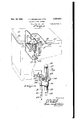
AUTOMATIC FUEL CONTROL- Filed Nov. 18, 1959 2 Sheets-Sheet 1 r in; 01.71
Nov. 16, 1943. 1. v. BRUMBAUGH ETAL AUTOMATIC FUEL CONTROL Filed Nov. 18, 1939 2 Sheets-Sheet 2 Patented Nov. 16, 1943 AUTOMATIC FUEL coN'rnoL Isaac V. Brumbaugh, Lester S. Kauifman, and Harold C. Reinhart, St. Louis, Mo., assignors to American Stove Company, St. Louis, Mo., a corporation of New Jersey Application November 18, 1939, Serial No. 305,200-
Claims.
The present invention pertains to a safety fuel control valve in combination with an automatic ignition means for a gaseous fuel burner and pertains even more particularly and specifically to an automatic ignition means for the oven or broiler burner of 'a gas cooking range.
In respect to automatic lighters or automatic ignition installations for cooking range burners, and especially burners used for broiling, it has been found that the flame of the broiler burner interferes with the flame of that burner of the ignition means that is used to heat the thermal member of the ignition means and that this interference may cause the valve of 'the safety fuel control to throttle, and, in extreme cases, to close. Such interference is therefore highly undesirable in that it interferes with the proper operation of the range in that throttling or closing of the safety fuel control valve either reduces or entirely cuts off the flow of gas to the oven broiler burner at a time not intended or desired.
Therefore one of the primary objects of the present invention is that of providing an automatic lighter or ignition means, including a safety fuel control valve, for oven and broiler burners which overcomes any possibility of poor, inefiicient or faulty operation by reason of interference from the flame burned at the oven or broiler burner.
In the accomplishment of the foregoing object and improved result, other specific objects are obtained and specific novel features of construction and arrangement are utilized the exact nalowing description when read in the light of the accompanying drawings.
The present invention has also as an object the provision of a device of the character described which is comparatively cheap of manufacture and cheap and simple of application to a range and a device which because of its simplicity and construction is not only highly eflicient in operation but will operate over long periods of time with the minimum of likelihood of any break-down which would cause failure of operation or the necessity of replacement of parts. y
In the drawings the invention is illustrated as being embodied in a gas cooking range, and
Fig. 1 is a fragmentary view in front elevation of a gas cooking range having applied thereto the present invention.
Fig. 2 is a perspective view which more clearly illustrates the respective positioning of the main light burners.
Describing the invention first in broad terms, A designates any conventional type of gas cooking range having therein a broiler chamber which lies behind .a suitable door I. In accordance with customary and accepted practice there is in the upper end of the broiler chamber a broiler burner B. Remotely positioned in respect to the broiler burner there is a safety fuel control valve designated as an entirety at C. An auxiliary burner is designated as an entirety at D. This burner D is separated from the main broiler burner B but a constant burning pilot light E is positioned between the broiler burner B and the auxiliary burner D as will be described hereinafter. The thermal member F is closely associated with the auxiliary burner D.
Describing the invention in detail but first having reference to the broiler burner B, it will be seen that this burner is of rectangular form and has its burner orifices 2 disposed in a manner to direct the flames 3 of the burner downwardly and outwardly. One leg 4 of the burner is pro vided .with an extension 5 to which is connected the burner intake manifold pipe 6 which extends downwardly at right angles to the burner and is of considerable length so that its lower end I is disposed a considerable distance below the burner. The intake and lower end 1 of the pipe is provided with the usual primary air inlet 8 under the control of an adjustable shutter 9. A second leg I!) of the burner is provided with an outwardly extending supplemental stub leg I l which is provided with suitable burner orifices so as to support the flames 12 (see Fig. 2) when gas is delivered to th broiler burner. It will be observed that the stub leg I I removes the flames of the main burner B proper from the flames of the auxiliary burner D.
The safety fuel control valve C lies in approximately the same horizontal plane with the lower end 1 of the broiler burner intake manifold pipe 6 and by reference to Figure 3 of the drawings it will be seen that it comprises a housing having therein an inlet chamber I3 which communicates with the supplemental outlet chamber l4 through a valve seat IS. The communicating passageway through the valve seat is under the control of a valve I6 which is normally urged towards a closed position by the bias of a coil spring l1. The inlet chamber of the housing is provided with an internally threaded inlet opening to which is attached a gas supply pipe I9 which has connection with the main gas supply manifold pipe 2| of the range through a manual operable valve 22. The supplemental and outlet chamber l4 of the housing is provided with an internally threaded outlet opening 23 to which is connected a short length of conduit 24 carrying at its end (see Fig. 2 of the drawings). an outlet nozzle 25 which is disposed within the bell shaped lower inlet end 1 of the broiler burner intake manifold pipe 6-.
One wall of the safety control valve housing is provided with a hollow internally threaded boss 26 which threadedly receives one end of a tube 21. This tube is of considerable length and has its upper threaded end 28 terminating at a point about even -with or slightly below the top of the broiler burner B.
The tube 21 has sufficient strength and rigidity to serve as a support for the auxiliary burner D. The auxiliary burner D comprises a carrier designated as an entirety at 29 which is of a U shape in side elevation configuration to provide two oppositely positioned legs 30 and 3|. The upper threaded end 28 of the tube 21 is threadedly received within the internally threaded opening 32 of the carrier leg 3 I. The auxiliary burner proper comprises a pair of oppositely disposed and spaced burner jets 33 and 34 which are threadedly mounted in the base or bottom 35 of the carrier and have communication with the gas conduit 36 which is also positioned in the carrier base and extends downwardly. therefrom into an externally threaded pipe-like extension '31 with which one end 38 of a fuel pipe 39 has communication. The opposite end of the fuel pipe 39 (see Fig- 1 of the drawings) has connection as at 40 with the 'main broiler burner fuel conduit 20 at a point well in front of the safety control valve C. The conduit 39 is provided with a manually controlled valve 41 which can readily be of the needle valve type and by which the size of the flames 42 burned at the auxiliary burner jets 33 and 34 may be controlled. It will be understood that whenever the manual valve 22 is moved to an open position for the purpose of obtaining fuel delivery to the main' broiler burner B fuel will also be delivered through the conduit 39 to the auxiliary burner jets 33 and 34. Fuel will of a certainty reach the auxiliary burner but as to whether or not the fuel will reach the main broiler burner B will depend upon whether the safety fuel control valve I6 is in an open or a closed position.
Primary air is supplied to the fuel for the auxiliary burner through an air inlet opening 43 in the conduit extension 31. The amount of air admitted through this opening can be adjusted by setting of the nut 44 which is locked in its set position by a lock nut 45.
The thermal element F can be either a rod or a tube and is composed of a material having a high coeflicient of thermal expansion. One end of the thermal member is supported in a suitable socket-46 provided in the carrier leg 30 while its other end 41 passes loosely through an opening 48 in the opposite leg 3| of the carrier and has abutment within the chamber 32 of this leg with the end of a rod 50 within the aforementioned tube 21. The rod 50 has the same coefiicient of heat expansion as its carrier tube 21. The thermal rod or tube F is disposed in separated parallel relationship to the bottom 35 of the carrier 23 and passes between the auxiliary burner jets 33 and 34 so that the flames 42 of these jets play upwardly along and around the thermal element.
The rod 50 is of a length substantially less than the length of the tube 21 and its lower end is provided with a tongue 5| which interlocks with the upper forked end 52 of a second thermal element 53. This second thermal element might be well called a compensator and is included within the apparatus to assure that the safety control valve does not approach too near its seat, and thereby reduce the fuel flow to the main broiler burner, when the broiler burner chamber reaches the high temperature which commonly prevails in broiling operations. The carrier 29 is composed of a negative material, that is to say, of a material having a low coeflicient of thermalexpansion but by reason of the fact that the broiler chamber does reach an extremely high temperature this carrier will expand to some extent which would, in the absence of the compensator or booster thermal element 53, permit the safety control valve to approach its seat and thus reduce the flame of the broiler burner which is of course not desirable. The compensator or booster thermal element 53 has a high coefficient of thermal expansion and when the temperature within the broiler chamber approaches or arrives at a point so as to cause expansion of the main thermal element carrier 25 this high temperature will cause the compensator or booster thermal element to have expanded. The coeflicient of thermal expansion of the booster thermal element 53 is greater than the coefficient of thermal expansion of the tube 21 and rod 50 but can be of a lower coefficient of thermal expansion than that inherent in the main thermal element F.
The booster thermal element 53 extends to the lower end of the tube 21 and has operative engagement with a pin 54 which pin extends into the chamber 14 of the safety control valve housing for operative engagement with a lever 55 at a point intermediate its ends but closely adjacent the end 56 of said lever. This lever is fulcrummed on a pin 51 carried by a screw 58 which is adjustable within a boss 59 of the housing. Externally of the housing the screw is provided with a curf 60 to provide convenient adjusting means and as an assistance in determining the setting of the fulcrum the screw carries a pointer 51 movable over a suitable dial 62.
Expansion of the thermal elements will rock the lever 55 on its fulcrum and move its forked end 63 in a direction towards the valve i6. A guide pin 64 extends through the forked end of the lever. A sleeve 65 is reciprocable on said guide pin and interposed between the lever and the valve to constitute an operating connection between the valve and lever so that when the lever is actuated by the thermal elements it will force the valve off of its seat against the pressure of the coil spring 11.
The pilot burner or light E is suitably secured to the auxiliary burner leg 3| such as by a clamp 86 and the flame 61 burned by the pilot is sufficiently close to one of the auxiliary burner jets as to ignite that jet when fuel is delivered to the auxiliary burner. The other auxiliary burner jet will be ignited from the first auxiliary burner jet. The pilot light flame is also positioned sufficiently close to the burner orifices in the supplemental or stub leg ll of the main broiler .burner as to cause ignition of the gas issuing therefrom and ignition of this gas in the supplemental or ignition leg ll of the broiler burner will cause the entire burner to be ignited.
Most important of all it is to be noted that the pilot burner flame 61 is positioned or interposed between the main broiler burner B proper and the auxiliary burner flames 33 and 34 and that the flame burned by the pilot burner proper prevents the flames burned by the broiler burner reaching or interfering in any way with the auxiliary burner flames. The extremity of the stub leg may be near the pilot flame as shown in Fig. 4, or the leg may be somewhat shortened as shown in Fig. 2 so long as the pilot flame prevents the main burner flame from interfering with the auxiliary flame. It is of course understood that the principal function of the auxiliary flame is to cause the expansion of the member F and the operation, of the safety valve l6 to cause said valve I6 to permit the proper amount of fuel to flow to the main burner to maintain the desired heat produced by the main burner B.
The pilot burner E is constantly burning. It receives its gas from the main range gas manifold 2| independent of any of the heretofore described apparatus through a pipe 68 which has independent connection at 69 with the main fuel conduit 2|. A valve or the like provides a means for adjusting the size of the pilot light flame. Primary air for the pilot light burner is supplied through an air inlet opening I I In operation, the pilot light is constantly burning and assuming it is desired to broil something in the broiling oven the manual valve 22 is opened. The opening of this valve delivers gas to the intake chamber l3 of the safety control valve and simultaneously delivers gas to the auxiliary burner. The auxiliary burner is immediately ignited by the constant burning pilot light but the gas admitted to the intake chamber l3 can not reach the main broiler burner because at this time the safety control valve I6 is held closed by the coil spring l'l. There will be a short lapse of time between the opening of the manual valve 22 and the lighting of the broiler burner. This time lapse will be dependent upon the size of the flame burned at the auxiliary burner.
Within a comparatively shorttime the auxiliary burner has heated the thermal element F to a point where it has expanded to cause movement of the lever 55 and the opening of the valve I6 against the tension of its bias. Immediately this valve is opened gas flows to the broiler burner and is ignited by the constant burning pilot light.
No fuel can reach the main burner unless the pilot light burner is ignited. If the pilot burner is not ignited the auxiliary burner will not be ignited and the safety fuel control valve \will be closed to the passage of any fuel to the'main burner.
By reason of the constant pilot playing no part in the heating of the thermal element a very small flame can be maintained with a resultant small fuel consumption and cheap operation.
The arrangement makes it possible to place the auxiliary burner closely adjacent the main burn er and use a single pilot light as an ignition means for both of said burners.
The device can be used with burners other than broiler burners and the invention is to be limited only by the hereinafter appended claims.
We claim:
1. In a gas fired cooking range or the like, a closed cooking chamber having therein a main the auxiliary burner, said main burner being dislight burner disposed wholly within said cooking chamber, a fuel supply line to said m'ainburner having a manually operable valve therein and and said thermal member as to prevent the I flames burned at all but one of the ports of said main burner from themselves heating said thermal element or intermingling with the flames of the auxiliary burner, said main burner however having a burner lighter port positioned suflicient- 1y close to said auxiliary burner and said thermal element as to cause likelihood of the flame burned at said lighter port to interfere with the operation of the auxiliary burner and to affect said thermal element, the lighter port of said main burner being positioned to be ignited by said pilot light, and the position of the pilot light being such that the flame of said pilot light extends and forms a curtain between the flame burned at said main burner lighter port and said thermal element and the flames burned by said auxiliary 'burner.
2. In a gas fired cooking range or the like, a closed cooking chamber having therein a main burner, an auxiliary burner and a constant pilot light burner disposed wholly within said cooking chamber, a fuel supply line to said main burner having a manually operable valve therein and a normally closed Valve operable to an open position by a thermal responsive member, a fuel supply line to said auxiliary burner and through which fuel passes to said auxiliary burner upon the opening of said manually operable valve, a fuel line for constantly supplying fuel to said pilot burner, a thermal element positioned in said cooking chamber and adapted to open said normally closed valve and being disposed to be heated by said auxiliary burner, said auxiliary burner havinga burner port at which a flame burns directed to and on said thermal element and a second port at which a flame burns in a direction towards the pilot light burner and the main burner, said pilot burner being disposed to ignite posed sufficiently'remote to the auxiliary burner and said thermal member as to prevent the flames burned at all but one of the ports of said main burner from themselves heating said' thermal element or intermingling with the flames of the auxiliary burner, said main burner however having a burner lighter port positioned sufliciently close to said auxiliary burner and said thermal element as to cause likelihood of the flame burned at said lighter port to interfere with the operation of the auxiliary burner and to affect said thermal element, the lighter port of saidv main burner being positioned to be ignited by said pilot light, and the position of the pilot light being such that the flame of said pilot light extends and forms a curtain between the flame burned at said main burner lighter port and said thermal burner, an auxiliary burner and a consta'r'i tpilot element and the flames burned by said auxiliary burner.
3. In a gas fired cooking range or the like, a closed broiling oven having therein a main burner disposed in substantially a horizontal plane and adapted to burn a plurality of flames directed downwardly and outwardly, one of the burner ports of said main burner being a lighter port, an auxiliary burner located adjacent the lighter port of said main burner and wholly within said oven, a fuel'supply line to said main burner having therein a manually operable valve and a normally closed valve operable to an open position by a thermal responsive member, a fuel line to said auxiliary burner and through which fuel passes to said auxiliary burner upon the opening of said manually operable valve, a constant burning pilot light disposed between the lighter port of the main burner and said auxiliary burner, a thermal responsive member positioned within the oven and adapted to operate said normally closed valve and being disposed to be heated by a flame burned by said auxiliary burner, and the position of the pilot light being such that the flame burned by said pilot light burner extends and forms a curtain between the flame burned at the lighter port of said main burner and the flames burned by said auxiliary burner and serves as a means to ignite both of said main and auxiliary burners, whereby the flame of the main burner is prevented from intermingling with or detrimentally affecting the thermal responsive element heating flame burned by the auxiliary burner.
4. In a gas fired cooking range or'the like, a closed cooking oven having therein a main burner, a gas supply line to said burner having therein a manually operable valve and a normally closed valve operable to an open position by a thermally responsive member, said main burner having a burner port operating as a lighter port I for the remaining ports of said burner, a thermally responsive member disposed adjacent the said lighter port of the main burner and having operable connection with said normally closed valve and adapted when heated to open the same, an auxiliary burner receiving its fuel from the fuel supply line to the main burner but subject to the control only of said manually operable valve, said auxiliary burner having a pair of burner ports disposed at opposite sides of said thermal member whereby burning flames are directed along and about said member, one of said burner ports being positioned between said thermal member and the lighter port of said main burner, aconstant burning pilot light positioned between said last named auxiliary burner burner port and the lighter port of said main burner, a third burner port of said auxiliary burner being adapted to burn a flame directed toward said constant pilot light burner, said constant pilot light burner acting to ignite the fuel jissuing from the main burner light port and from the third port of said auxiliary burner, and the remaining two ports of said auxiliary burner being adapted to be ignited from the flame burned at said third auxiliary burner port, whereby an automatic safety ignition means of the type described is provided.
5. In a gas fired cooking range or the like, a closed cooking chamber having therein a main burner, an auxiliary burner and a constant pilot light burner disposed wholly within said cooking chamber, a fuel supply line to said main burner having a manually operable valve therein and a normally closed valve operable to an open position by a thermal responsive member, a fuel supply line to said auxiliary burner and through which fuel passes to said auxiliary burner upon 5 the opening of said manually operable valve, a fuel line for constantly supplying fuel to said pilot burner, said auxiliary burner comprising a housing having apair of burner ports at opposite sides thereof, a thermal element mounted on said auxiliary burner housing and being disposed between said auxiliary burner ports, said auxiliary burner acting to heat said thermal element and said element upon being heated adapted to open said normally closed valve, said pilot burner being disposed to ignite the auxiliary burner, said main burner being disposed sufliciently remote to the auxiliary burner and said thermal member as to prevent the flames burned by said main burner from themselves heating said thermal element or intermingling with the flames of the auxiliary burner, said main burner however having a burner lighter port positioned sufficiently close to said auxiliary burner and said thermal element as to cause likelihood of the flame burned at said lighter port to interfere with the operation of the auxiliary burner and to affect said thermal element, the lighter port of said main burner being positioned to be ignited by said pilot light, and ,the position of the pilot light being such that the flame of said pilot light extends and forms a curtain between the flame burned at said main lighter port and said thermal element and the flames burned by said auxiliary burner.
6. In a device of the character described, a closed cooking chamber, a main burner therein, a small constant burning pilot light in said chamber, a thermal member, an auxiliary burner for initially heating said thermal member, a fuel 40 control valve operable by said thermal member -for controlling the flow of fuel to said main burner, said pilot light being positioned to ignite said main and auxiliary burners, and said thermal member being in said chamber and responsive to the heat generated therein by said main burner to cause a further opening of said burner fuel control valve as the heat in said chamber increases due to the operation of said main burner.
7. In a device of the character described, a closed broiling chamber, a horizontally disposed gas burner'in the upper end of said chamber for heating the chamber and being provided below its top with burner orifices disposed to burn downwardly and outwardly projecting flames, a fuel supply line for said burner, a normally closed valve in said fuel line positioned in the lower end of said chamber, said valve acting only to control the flow of fuel to said chamber 'heating burner, an elongated support extending from vsaid valve and carrying a thermal element posi- .tioned in the upper end of said chamber adjacent said main burner, said thermal element adapted to operate said fuel valve, an auxiliary burner positioned in said broiling chamber closely adjacent said thermal element and adapted to heat the same, and a constant burning pilot light positioned intermediate the main burner and said auxiliary burner and adapted to light both of said burners when gas is supplied to the same.
8. A construction such as defined in claim 7 wherein, the thermal element is in the form of an elongated rod member disposed in a vertical burner ports disposed to burn flames at opposite sides of said thermal element and upwardly along and about the same.
9. A construction such as defined in claim 6 wherein, said auxiliary burner is localized to the immediate vicinity of said thermal element and is entirely within said closed cooking chamber and is of small gas consumption by reason of having a minimum number of burner orifices.
10. In a gas fired cooking range or the like, a closed cooking oven having therein a main burner, a gas supply line to said burner having therein a manually operable valve and a normally closed valve operable to an open position by a thermally responsive member, said main burner having a burner port operating as a lighter port for the remaining ports of said burner, a thermally re'sponsivemember disposed adjacent the said lighter port of the main mumer and having operable connection with said normally closed valve and adapted when heated to open the same,
an auxiliary burner receiving its fuel from the fuel supply line to the main burner but subject to the coritrol only of said manually operable valve, said auxiliary burner having a pair of ports the first of which burns a flame directed along and about said thermal member, a constant burning pilot light positioned between said auxiliary first burner port and the lighter port of said main burner, said auxiliary burner second burner port being positioned between the first named auxiliary burner port and said constant burning pilot light, said constant pilot light burner acting when said manually operable and thermally operable valves are open to ignite the fuel issuing from the main burner lighter port and from the second port of said auxiliary burner, and fuel issuing from the first named auxiliary lighter port being ignited from the flame burned at the second port of said auxiliary burner.
11. In a device of the character described, a closed chamber having a horizontally disposed heating burner therein, a fuel supply line to said burner having therein a normally closed valve, a thermal responsive member adapted upon being heated to open said valve, said thermal element comprising an elongated rodhaving a high coefficient'of heat expansion and an elongated carrier therefor having a lower coefficient of heat expansion, said rod and carrier being positioned at one side and adjacent said burner and disposed in a vertical plane, an auxiliary burner lovided and is positioned to automatically ignite fuel delivered to either or both the heating burn er and auxiliary burner.
13. In a device of the character described, a'
chamber having a horizontally disposed heating burner therein, a fuel supply line to said burner having therein a normally closed valve, a thermal responsive member adapted upon being heated to open said valve, said thermal element comprising an elongated rod, having a high 00- efficient of heat expansion and an elongated carrier therefor having a lower coeflicient of heat expansion, said rod and carrier being positioned at one side and adjacent said burner and disposed in a vertical plane, an auxiliary burner and 'a fuel supply line therefor, said auxiliary burner provided with a pair of burner ports, and said burner ports-being positioned at opposite sides of said thermo responsive member andbeing disposed to direct their flames inwardly toward and upwardly along and around said member.
14. A construction such as defined in claim 11 wherein, a constant burning pilot light is provided and is positioned to automatically ignite fuel delivered to either or both the heating burner and auxiliary burner.
15. In a device of the character described, a cooking chamber, a main burner horizontally disposed therein and provided below its top with burner orifices disposed to burn downwardly and outwardly projecting flames, a normally closed fuel control valve disposed in said chamber and adapted to control the flow of fuel to said main burner, a thermal member in said chamber and cated substantially along side of said main burnlocated closely adjacent but in spaced relationship to said main burner, said thermal member being operatively connected with said normally closed fuel control valve and upon being heated operating to open said valve, a constant burning pilot light in said chamber positioned in the space between said main burner and said thermal member and provided with a burner. orifice, an auxiliary burner located wholly within said chamber for heating said thermal member and provided with a burner orifice positioned to burn a flame at a point intermediate the thermal member and said constant burning pilot light flame, the disposition of the burner orifices of said main burner, pilot light burner and auxiliary burner being such that the flames burned at said orifices are all located substantially in the same horizontal plane, and the burner orifice of the pilot light burner being further so positioned that the flame of said pilot light forms a cur tain between the flame of the auxiliary burner and the nearest flame of the main burner, for the purpose described.
. ISAAC V. BRUMBAUGH. LESTER S. KAUFFMAN. HAROLD C. REINHART.
Priority Applications (1)
| Application Number | Priority Date | Filing Date | Title |
|---|---|---|---|
| US305200A US2334603A (en) | 1939-11-18 | 1939-11-18 | Automatic fuel control |
Applications Claiming Priority (1)
| Application Number | Priority Date | Filing Date | Title |
|---|---|---|---|
| US305200A US2334603A (en) | 1939-11-18 | 1939-11-18 | Automatic fuel control |
Publications (1)
| Publication Number | Publication Date |
|---|---|
| US2334603A true US2334603A (en) | 1943-11-16 |
Family
ID=23179761
Family Applications (1)
| Application Number | Title | Priority Date | Filing Date |
|---|---|---|---|
| US305200A Expired - Lifetime US2334603A (en) | 1939-11-18 | 1939-11-18 | Automatic fuel control |
Country Status (1)
| Country | Link |
|---|---|
| US (1) | US2334603A (en) |
Cited By (5)
| Publication number | Priority date | Publication date | Assignee | Title |
|---|---|---|---|---|
| US2517782A (en) * | 1944-02-05 | 1950-08-08 | Frank A Gauger | Flash tube for ignition of gas burners |
| US2696877A (en) * | 1950-11-24 | 1954-12-14 | Roper Corp Geo D | Burner igniter and safety control |
| US2726653A (en) * | 1951-07-07 | 1955-12-13 | Robertshaw Fulton Controls Co | Control and ignition system for gaseous fuel burners |
| US3213922A (en) * | 1965-10-26 | Control apparatus for fuel burning apxliances | ||
| US3237296A (en) * | 1958-09-29 | 1966-03-01 | Robertshaw Controls Co | Method of making a thermostatic control device |
-
1939
- 1939-11-18 US US305200A patent/US2334603A/en not_active Expired - Lifetime
Cited By (5)
| Publication number | Priority date | Publication date | Assignee | Title |
|---|---|---|---|---|
| US3213922A (en) * | 1965-10-26 | Control apparatus for fuel burning apxliances | ||
| US2517782A (en) * | 1944-02-05 | 1950-08-08 | Frank A Gauger | Flash tube for ignition of gas burners |
| US2696877A (en) * | 1950-11-24 | 1954-12-14 | Roper Corp Geo D | Burner igniter and safety control |
| US2726653A (en) * | 1951-07-07 | 1955-12-13 | Robertshaw Fulton Controls Co | Control and ignition system for gaseous fuel burners |
| US3237296A (en) * | 1958-09-29 | 1966-03-01 | Robertshaw Controls Co | Method of making a thermostatic control device |
Similar Documents
| Publication | Publication Date | Title |
|---|---|---|
| GB1115999A (en) | Pilot burner apparatus | |
| US2098192A (en) | Ignition and control device for oven burners | |
| US2072034A (en) | Gas range lighter and control | |
| US2334603A (en) | Automatic fuel control | |
| US2048065A (en) | Gas range and automatic lighter therefor | |
| US2011090A (en) | Ignition device | |
| US1977150A (en) | Automatic lighter and gas cut-off | |
| US2490729A (en) | Flash ignition and safety control | |
| US2164887A (en) | Safety control and ignition means for multiple gas burners | |
| US1926218A (en) | Ignztek and control device fos | |
| US2258924A (en) | Automatic fuel control | |
| US2520542A (en) | Automatic gas burner control | |
| US2011111A (en) | Safety lighting device | |
| US2365102A (en) | Pilot fob gas burners | |
| US2898979A (en) | Gas-fueled burner | |
| US1956052A (en) | Gaseous fuel control system | |
| US2032045A (en) | Compensated pilot-controlled thermostat | |
| US1968319A (en) | Thermostat control of pilot flames | |
| US2040011A (en) | Gas range or similar appliance | |
| US1974319A (en) | Zjghting device | |
| US2696877A (en) | Burner igniter and safety control | |
| US1842331A (en) | Gaseous fuel control system | |
| US2916088A (en) | Fuel burner control apparatus | |
| US2104298A (en) | Automatic oven lighter | |
| US1340843A (en) | Delayed cut-off for bunsen gas-burners |