US2331663A - Oil burner - Google Patents
Oil burner Download PDFInfo
- Publication number
- US2331663A US2331663A US329039A US32903940A US2331663A US 2331663 A US2331663 A US 2331663A US 329039 A US329039 A US 329039A US 32903940 A US32903940 A US 32903940A US 2331663 A US2331663 A US 2331663A
- Authority
- US
- United States
- Prior art keywords
- pipe
- gates
- discharge end
- burner
- head
- Prior art date
- Legal status (The legal status is an assumption and is not a legal conclusion. Google has not performed a legal analysis and makes no representation as to the accuracy of the status listed.)
- Expired - Lifetime
Links
Images
Classifications
-
- F—MECHANICAL ENGINEERING; LIGHTING; HEATING; WEAPONS; BLASTING
- F23—COMBUSTION APPARATUS; COMBUSTION PROCESSES
- F23D—BURNERS
- F23D11/00—Burners using a direct spraying action of liquid droplets or vaporised liquid into the combustion space
- F23D11/36—Details
Definitions
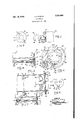
- FIG. 1 is an assembly view showing my improved burner as installed in a furnace
- FIG. 2 is an end view of the burner with parts broken away;
- Fig. 3 is a longitudinal sectional .view through the forward end portion of theburner;
- Fig. 4 is a detailed sectional view taken as along the line :34 of Fig. 2';
- Fig. 5 is anenlarged planview showing a part employed; l I I Fig. 6 is an elevational view showinga pair of gates employed; and
- Fig. 7 is a view similar to Fig.4fbut showing amodification.
- g p e Referring in detail to the drawing at: E is shown a portion of a furnace including 'a front I wall E3 in which is mounted the discharge portion of an oil burner air blast pipe l4 forming part of a burner generally designated i and located atthe forward side of i5 is a gunetype burner. is concernedwith the air blast pipe and particularly with the discharge end thereof.
- Said pipe includes a flange iii "which extends beyond the inner and outer surfaces of the pipe and provides a hat end surface for a purpose to be described. At one point saidfiange is enlarged or thickened providing a boss I7.
- the inner end of the pipe sectio M is provided with lugs 58 which are secured by bolts It? to the corresponding lugs 28 of a pipe section 2i.
- Withinthe pipe M and extending longitudinally thereof is an oil supply tube 22 provided at its forward end with an oil spray nozzle 23 located immediately adjacent the flange 5 6.
- an air whirler generally designated Hand preferably ofthe type disclosed in my Patent 2,146,250
- the burner l 5 includes a pumpandfanor blower 5s which the gate also be turned and wherebya stream of air is forced throughthe pipe [4 to take'up and mix ture therewith.
- This invention is of theflame of the burner; Disposed against the outer side of" the flange l6 and shaped to follow the contour of the outer edge thereof is a frame or spacer means 25; the inneredges of which comprise lateral guides for a pair of gates 26 and 2'! respectively.
- These gates (see Fig; 6) comprise a pair of flat plate-like members of 2B is provided in one edge with a recess or cut-out 28 while the gate-21, iSprovidedwith a corresponding recess 29.
- gate 26 The upper and lower edges of gate 26 are guided by the edges of the'fraine 25 and such gate includes an extension 3D, the inner edge of which is a guidefor the lower edge of gate 27, while the upper edge of such gate 21 is guided by the inner upper edge'of the frame 25.
- completes the discharge end of the air blast pipe and comprises a short pipe-like section 32 and a flange 33 which latteroverlies portionsof the gates Ziiand 21 whereby to retain them within the frame 25.
- curing means 34 pass through the flange 33; the frame25, and the flange IE whereby the piece 8
- a washer-like member 42 Disposed under the head 35 is a washer-like member 42 having a. flattened edge portion 43 engaging. a correspondingly, shaped portion of r the boss. I! whereby the washer may not rotate about the bar 48.
- a sleeve or tubular piece. 44 is disposed about theforwardportion of bar and threaded into the boss I! and into engagement with the rear side of the washer 42.
- Bar 40 is provided with a flattened or squared portion to be engaged by a wrench or the like and tube 44 is provided with a similarly shaped portion 46 for the same purpose.
- An inspection of Fig. 1 will show that such portions 45 and 48 are at the forward side of the furnace so that engaged by a wrench after the burner is completely installed and sealed in place.
- the expertmaking the installation rotatesthe bar, 40 so asto'movethe gates toward and from one another until the flame desired for the particular installation is obtained.
- the operator applies a wrench to the tube portion 46 and threads the latter: up causing its inner end to force the washer "against the head 35 and the latter against the gates locking the parts inadjusted position.
- The; described turningof the sleeve 44 does undesult in the dis turbing of anyadjustments of the gates since the sleeve bears against the washer 42 and, owing tothe'flat sidedconstruct-ion of the latter at 43, it may not rotate and. thus turning movement of thesleeve,isnotimpartedto the head.
- the gates 26 and 21 are adjustable to adapt the burner for different capacities of fuel consumption.
- the use of the present structure eliminates the necessity for the four sizes of choke rings heretofore provided and of which the one best suited to any particular installation has heretofore been necessary. For example, heretofore one size of choke ring was used where a given capacity per hour was desired; a different size choke ring when a different capacity per hour is desired, etc.
- an air blast pipe an oil supply tube in said pipe, a nozzle on said tube adjacent the discharge end of said pipe, an inwardly directed flange on the discharge end of said pipe, gates at the outer side of said flange, means mounting said gates adjacent said flange for movement toward and from one another to vary the efiective diameter of the pipe outlet, and means outside of said pipe and extending longitudinally thereof'andoperable to adjust said gates and secure them in adjusted positions.
- an air blast pipe an oil supply tube in said pipe, a nozzle on said tube adjacent but inwardly of the discharge end of said pipe, an inwardly directed flange on the discharge endof said pipe, gates, means mounting said gates on said flange for movement toward and from one another to vary the effec- I tive diameter of the pipe outlet, means for adjusting said gates, said flange having an opening therethrough immediately above the lower internal surface of said pipe, one of said gates having a slot therein registering with said opening, and a drain nipple disposed in said opening and slot and extending to the outer side of said gates for draining oil'from the interior of said pipe.
- an air blast pipe an oil supply tube in said pipe, a nozzle on said tube adjacent the discharge end of the pipe, gates at the discharge end of the pipe, means mounting the gates on the pipe for movement toward and from one another to vary the effective diameter of the discharge end of the pipe, each of said gates having a slot therein, a head rotatably mounted adjacent the discharge end of the pipe, laterally spaced pins on said head eccentric to the axis thereof and entering said slots whereby on turning of the head the gates are moved toward or from each other, means outside said pipe and operable to turn said head, and other means outside said pipe and operable to force said head against said gates and thereby lock the latter in their adjusted positions.
- an air blast pipe an oil supply tube in said pipe, a nozzle on said tube adjacent the discharge end of said pipe, gates at the discharge end of the pipe, means mounting the gates on the pipe formovement toward and from one another to vary the effective diameter of the discharge end of the gates having a slot therein, a head rotatably mounted adjacent the discharge end of the pipe, laterally spaced pins on said head eccentric to the axis thereof and entering said slots whereby on turning of the head the gates are moved toward or from each other, means outside said pipe and operable to turn said head, a washer under said head, means holding said washer against turning movement, and turnable means engaging said washer and operable to force the same against said head and the latter against positions.
- an air blast pipe In an oil burner, an air blast pipe, an oil supply tube in said pipe, a nozzle on the tube adjacent the discharge end of the pipe, gates at the discharge end of the pipe, means mounting said gates on the pipe for movement toward and from one another to vary the eflective diameter of the discharge end of the pipe, each of said pipe, each of said gates in their adjusted.
- said head eccentric to laterally spaced pins on the axis thereof and entering said slots whereby on turning of the head the gates are moved toward or from each other, means outside said pipe and operable to turn said head, and a stiif spring associated with said means and urging it in a direction maintaining said head pressed against said gates whereby the latter are held against casual movement.
- an air blast pipe an oil supply tube in said pipe, a nozzle on said tube adjacent and substantially concentric with the discharge end of the pipe for spraying oil into the air stream moving from said pipe, plate-like gates mounted in the same plane on the discharge end of the pipe for relative sliding movement to and from abutting relation, said gates recessed in their opposing edges whereby when they are moved to abutting relation an opening substantially concentric with the discharge end of the pipe is defined by said gates, and means operable from the exterior of said pipe to adjust said gates toward and from one another.
- an air blast pipe an oil supply tube in said pipe, a nozzle on the end of said tube and located substantially at the discharge end of said pipe for spraying oil into the air stream moving from said pipe, flat plate like gates, means mounting said gates on the discharge end of said pipe for sliding movement toward and from one another in directions transversely ofsaid pipe, operating means extending rearwardly from said discharge end of the pipe, means mounting said ment relative to said pipe, and connections between said operating means and said gates whereby on predetermined movements of said operating means said gates may be moved transversely of the end of said pipe toward and from one another to partly close the discharge end of the pipe when moved toward one another.
Landscapes
- Engineering & Computer Science (AREA)
- Chemical & Material Sciences (AREA)
- Combustion & Propulsion (AREA)
- Mechanical Engineering (AREA)
- General Engineering & Computer Science (AREA)
- Nozzles For Spraying Of Liquid Fuel (AREA)
Description
J: A. DELlA Oct. 12, 1943.
OIL BURNER Filed April 11',
INVENTOR J sEPH A. D'EUA This invention relates to .provements in oil burners andhas Patented Oct. 12, 1943 OIL BURNER 1 Joseph A. DElia, Bridgeport, Conn. Application April 11, 1940, Serial No. 329,039
8 Claims. (01. 158-45) new and useful imparticular relation to an adjustable means for controlling the flame of a gun type of.oil burner. j
The objects andadvantages of the invention will become apparent from a consideration of the following detailed description taken in connection with the accompanying drawing whereina satisfactory embodiment of the invention isv shown. However, it is to be understoodthat the invention is not limited to the details disclosed but includes all such variations and modifications as fall within the spirit-of the invention and the scope of the appended claims.
In the drawing Fig. 1 is an assembly view showing my improved burner as installed in a furnace;
- Fig. 2 is an end view of the burner with parts broken away;
Fig. 3 is a longitudinal sectional .view through the forward end portion of theburner; Fig. 4 is a detailed sectional view taken as along the line :34 of Fig. 2';
Fig. 5 is anenlarged planview showing a part employed; l I I Fig. 6 is an elevational view showinga pair of gates employed; and
Fig. 7 is a view similar to Fig.4fbut showing amodification. g p e Referring in detail to the drawing at: E is shown a portion of a furnace including 'a front I wall E3 in which is mounted the discharge portion of an oil burner air blast pipe l4 forming part of a burner generally designated i and located atthe forward side of i5 is a gunetype burner. is concernedwith the air blast pipe and particularly with the discharge end thereof.
Said pipe includes a flange iii "which extends beyond the inner and outer surfaces of the pipe and provides a hat end surface for a purpose to be described. At one point saidfiange is enlarged or thickened providing a boss I7. The inner end of the pipe sectio M is provided with lugs 58 which are secured by bolts It? to the corresponding lugs 28 of a pipe section 2i. Withinthe pipe M and extending longitudinally thereof is an oil supply tube 22 provided at its forward end with an oil spray nozzle 23 located immediately adjacent the flange 5 6. Disposed aboutthe forward end of pipe 22 is an air whirler generally designated Hand preferably ofthe type disclosed in my Patent 2,146,250
of February '7, 1 939. It will be understood that the furnace. Burner The present invention the burner l 5 includes a pumpandfanor blower 5s which the gate also be turned and wherebya stream of air is forced throughthe pipe [4 to take'up and mix ture therewith.
This invention is of theflame of the burner; Disposed against the outer side of" the flange l6 and shaped to follow the contour of the outer edge thereof is a frame or spacer means 25; the inneredges of which comprise lateral guides for a pair of gates 26 and 2'! respectively. These gates (see Fig; 6) comprise a pair of flat plate-like members of 2B is provided in one edge with a recess or cut-out 28 while the gate-21, iSprovidedwith a corresponding recess 29.
The upper and lower edges of gate 26 are guided by the edges of the'fraine 25 and such gate includes an extension 3D, the inner edge of which is a guidefor the lower edge of gate 27, while the upper edge of such gate 21 is guided by the inner upper edge'of the frame 25. An endpiece 3| completes the discharge end of the air blast pipe and comprises a short pipe-like section 32 and a flange 33 which latteroverlies portionsof the gates Ziiand 21 whereby to retain them within the frame 25. curing means 34 pass through the flange 33; the frame25, and the flange IE whereby the piece 8| and the-frame 25 are secured to the section It and serve to secure: the gates 26 and 21 in place but in such manner that said gates may be adjusted relative to one'another and to the other mentioned parts. i
In the forward portion of the boss 51', immediately under the free end of gate extension and the lowerpart of gate 21 'lsahead 35 in the'formof a disc and this head isprovided with forwardly projecting pins 36 and 3! entering slots 38 and 39 in the gate 21 and extension 30 respectively. Head 35 is rigid or integral with a rearwardly extending bar 40, the rear end of which has bearingin a lug 45 formed with the outerwall of the pipe I 4. t
Disposed under the head 35 isa washer-like member 42 having a. flattened edge portion 43 engaging. a correspondingly, shaped portion of r the boss. I! whereby the washer may not rotate about the bar 48. A sleeve or tubular piece. 44 is disposed about theforwardportion of bar and threaded into the boss I! and into engagement with the rear side of the washer 42. With the described constructionit will be clear that on the; bar 46, being turned, thehead '35 'will 7 due-to its pin'and slot connec n i ht es tes and t la te v with the oil sprayed from the nozzle 23 and form a combustible mixconcerned with the control [Bolts or othersethe parts may be rings have been provided outermost positions and when they are so locatedthe opening through the flange i6 is substantially fully exposed. The dotted lines in Fig. 2 show the gates in their innermost position and it will be seen that when the gates are in such position, with their forward opposing edges abutting, the effective size of the discharge opening beyond the nozzle 23 is very materially reduced.
Heretofore various sizes of so-called reducer for installation in the but these are difficult to install after set up and in addition, there pipe 14 the burner is once is no adjustment except as provided by the difi'erent-sizes of rings. With the present. arrangement the ,gatesmay be minutely-adjusted toward and-from one another 'until'the exact flame desired is obtained. Ifjthe gates are nearly closed and the burner ofrelatively large capacity, a
hard long flame is obtained and the operator then makes an adjustment to-open the gates an additional'amount.
When the. exact desired flame is obtained, the operator applies a wrench to the tube portion 46 and threads the latter: up causing its inner end to force the washer "against the head 35 and the latter against the gates locking the parts inadjusted position. The; described turningof the sleeve 44 does notresult in the dis turbing of anyadjustments of the gates since the sleeve bears against the washer 42 and, owing tothe'flat sidedconstruct-ion of the latter at 43, it may not rotate and. thus turning movement of thesleeve,isnotimpartedto the head.
Cutting ofiqof the drops of oil leaking from-the nozzle 2-3 and if so they do not drop from the forward tip-oi the nozzle but run down the end thereof and drop fromthe lowest point of the nozzle. Thus, these drops 'do' not fall into the space. in which the gates move and will not carbonize and cause any binding or locking of the latter although it isnotedthat once these gates have been adjusted atthe time of installation, itis not planned that the adjustment should be changed by anyone other than an expert on burners.
To remove any drops of oil falling from the nozzle as above described, 1 form a depression '41 in thebott'om wall oi pipe Man'dprovide an opening in the flange i6 aligning with said depression and then provide a slot 48 in the extension 30 of the gate 25-. In this opening and slot '1 mounta short-nipple 48 through which any drops of oil falling from the nozzle: may pass. InFigl-iithe' nipple 49 will discharge onto thepipe-like portion 110i the part 31 from which the oil may drain orbe evaporated and on the burner next-being operated.
with the disclosed construction; I find that burner may result in a few with one size of burner I can take care of all requirements of the domestic trade where heretofore it has been necessary to manufacture and stock three different sizes of burners. The gates 26 and 21 are adjustable to adapt the burner for different capacities of fuel consumption. The use of the present structure eliminates the necessity for the four sizes of choke rings heretofore provided and of which the one best suited to any particular installation has heretofore been necessary. For example, heretofore one size of choke ring was used where a given capacity per hour was desired; a different size choke ring when a different capacity per hour is desired, etc.
Referring to the modification of Fig. 7, it is noted that a somewhat simpler construction is provided in that the tube 44 and washer 42 have been dispensed with thus eliminating the necessity for the threading of the opening in the boss ll; However, the bar 40a including the wrench engaging-portion 4% has been provided with a reduced end portion 50, about which is disposed a coil spring 5! partially entering a socket 52 in the enlargement 4i and bearing against the shoulder 53 of the rod or bar 400.; Spring 51 is a heavy stiff spring and constantly presses rod 49a. in a direc tion to press the head 35 against the gates 5 and 27 whereby there will be no casual movement of the parts. To adjust the gates a wrench is applied to part45b andthe rod 400. is turned and the stiff spring 5! keeps, the parts in their adjusted positions.
Having thus set forth the nature of my invention, what I- claim is:
1. In an oil burner, an air blast pipe, an oil supply tube in said pipe, a nozzle on said tube adjacent the discharge end of said pipe, an inwardly directed flange on the discharge end of said pipe, gates at the outer side of said flange, means mounting said gates adjacent said flange for movement toward and from one another to vary the efiective diameter of the pipe outlet, and means outside of said pipe and extending longitudinally thereof'andoperable to adjust said gates and secure them in adjusted positions.
2. In an oil burner, an air blast pipe, an oil supply tube in said pipe, a nozzle on said tube adjacent but inwardly of the discharge end of said pipe, an inwardly directed flange on the discharge endof said pipe, gates, means mounting said gates on said flange for movement toward and from one another to vary the effec- I tive diameter of the pipe outlet, means for adjusting said gates, said flange having an opening therethrough immediately above the lower internal surface of said pipe, one of said gates having a slot therein registering with said opening, and a drain nipple disposed in said opening and slot and extending to the outer side of said gates for draining oil'from the interior of said pipe.
3.In an oil burner, an air blast pipe, an oil supply tube in said pipe, a nozzle on said tube adjacent the discharge end of the pipe, gates at the discharge end of the pipe, means mounting said gates on the pipe for movement toward and from one another to vary the effective diameter of the discharge end of the pipe, each of said gates having a slot therein, a head rotataioly mounted adjacent the discharge end of the pipe, laterally spaced pins on said head eccentric tothe axis thereof" and entering said slots whereby on turning of the head the gates are moved toward or from each other, and means outside said pipe and operableto-tum said head,
the gates to secure the 4. In an oil burner, an air blast pipe, an oil supply tube in said pipe, a nozzle on said tube adjacent the discharge end of the pipe, gates at the discharge end of the pipe, means mounting the gates on the pipe for movement toward and from one another to vary the effective diameter of the discharge end of the pipe, each of said gates having a slot therein, a head rotatably mounted adjacent the discharge end of the pipe, laterally spaced pins on said head eccentric to the axis thereof and entering said slots whereby on turning of the head the gates are moved toward or from each other, means outside said pipe and operable to turn said head, and other means outside said pipe and operable to force said head against said gates and thereby lock the latter in their adjusted positions.
5. In an oil burner, an air blast pipe, an oil supply tube in said pipe, a nozzle on said tube adjacent the discharge end of said pipe, gates at the discharge end of the pipe, means mounting the gates on the pipe formovement toward and from one another to vary the effective diameter of the discharge end of the gates having a slot therein, a head rotatably mounted adjacent the discharge end of the pipe, laterally spaced pins on said head eccentric to the axis thereof and entering said slots whereby on turning of the head the gates are moved toward or from each other, means outside said pipe and operable to turn said head, a washer under said head, means holding said washer against turning movement, and turnable means engaging said washer and operable to force the same against said head and the latter against positions.
6. In an oil burner, an air blast pipe, an oil supply tube in said pipe, a nozzle on the tube adjacent the discharge end of the pipe, gates at the discharge end of the pipe, means mounting said gates on the pipe for movement toward and from one another to vary the eflective diameter of the discharge end of the pipe, each of said pipe, each of said gates in their adjusted.
gates having a slot therein, a head rotatably mounted adjacent the discharge end of the pipe,
said head eccentric to laterally spaced pins on the axis thereof and entering said slots whereby on turning of the head the gates are moved toward or from each other, means outside said pipe and operable to turn said head, and a stiif spring associated with said means and urging it in a direction maintaining said head pressed against said gates whereby the latter are held against casual movement.
7. In an oil burner, an air blast pipe, an oil supply tube in said pipe, a nozzle on said tube adjacent and substantially concentric with the discharge end of the pipe for spraying oil into the air stream moving from said pipe, plate-like gates mounted in the same plane on the discharge end of the pipe for relative sliding movement to and from abutting relation, said gates recessed in their opposing edges whereby when they are moved to abutting relation an opening substantially concentric with the discharge end of the pipe is defined by said gates, and means operable from the exterior of said pipe to adjust said gates toward and from one another.
8. In an oil burner, an air blast pipe, an oil supply tube in said pipe, a nozzle on the end of said tube and located substantially at the discharge end of said pipe for spraying oil into the air stream moving from said pipe, flat plate like gates, means mounting said gates on the discharge end of said pipe for sliding movement toward and from one another in directions transversely ofsaid pipe, operating means extending rearwardly from said discharge end of the pipe, means mounting said ment relative to said pipe, and connections between said operating means and said gates whereby on predetermined movements of said operating means said gates may be moved transversely of the end of said pipe toward and from one another to partly close the discharge end of the pipe when moved toward one another.
' JOSEPH A. DELIA.
operating means for move-
Priority Applications (1)
| Application Number | Priority Date | Filing Date | Title |
|---|---|---|---|
| US329039A US2331663A (en) | 1940-04-11 | 1940-04-11 | Oil burner |
Applications Claiming Priority (1)
| Application Number | Priority Date | Filing Date | Title |
|---|---|---|---|
| US329039A US2331663A (en) | 1940-04-11 | 1940-04-11 | Oil burner |
Publications (1)
| Publication Number | Publication Date |
|---|---|
| US2331663A true US2331663A (en) | 1943-10-12 |
Family
ID=23283606
Family Applications (1)
| Application Number | Title | Priority Date | Filing Date |
|---|---|---|---|
| US329039A Expired - Lifetime US2331663A (en) | 1940-04-11 | 1940-04-11 | Oil burner |
Country Status (1)
| Country | Link |
|---|---|
| US (1) | US2331663A (en) |
Cited By (2)
| Publication number | Priority date | Publication date | Assignee | Title |
|---|---|---|---|---|
| US2599153A (en) * | 1948-05-01 | 1952-06-03 | Reginald W Beckett | Oil burner of the atomizing type |
| US3138193A (en) * | 1960-11-23 | 1964-06-23 | James L Hagerman | Combustion of liquid fuel |
-
1940
- 1940-04-11 US US329039A patent/US2331663A/en not_active Expired - Lifetime
Cited By (2)
| Publication number | Priority date | Publication date | Assignee | Title |
|---|---|---|---|---|
| US2599153A (en) * | 1948-05-01 | 1952-06-03 | Reginald W Beckett | Oil burner of the atomizing type |
| US3138193A (en) * | 1960-11-23 | 1964-06-23 | James L Hagerman | Combustion of liquid fuel |
Similar Documents
| Publication | Publication Date | Title |
|---|---|---|
| US2259215A (en) | Spray gun | |
| US2501657A (en) | Fluid mixture and volume control valve | |
| US2723102A (en) | Valve for controlling gas | |
| US1940268A (en) | Spray gun | |
| US2331663A (en) | Oil burner | |
| US2987078A (en) | Gas valve | |
| US2852310A (en) | Hose nozzles | |
| US2504592A (en) | Pilot burner mount | |
| US1786330A (en) | Valve device | |
| US1439320A (en) | Nebulizer of liquids | |
| US2448159A (en) | Spray gun | |
| US2097397A (en) | Soldering torch valve | |
| US2751974A (en) | Venturi type proportional mixer with means for adjusting the effective cross sectional areas of the adjacent small extremities of the outwardly flared exhaust and inwardl tapered intake passages thereof | |
| US976221A (en) | Liquid-fuel burner. | |
| US2592056A (en) | Valve with adjustable flow control | |
| US2210476A (en) | Adjustable air register | |
| US2248932A (en) | Gas burner | |
| US2554470A (en) | Valve for controlling gas | |
| US1882600A (en) | Blow-off valve | |
| US1739428A (en) | Spray head | |
| US1482798A (en) | Valve | |
| US2554200A (en) | Nozzle | |
| US1843411A (en) | Liquid-fuel burner | |
| US2284995A (en) | Floor furnace valve | |
| US2744542A (en) | Mixing faucet for showers and the like |