US2324924A - Electrode holder - Google Patents
Electrode holder Download PDFInfo
- Publication number
- US2324924A US2324924A US475841A US47584143A US2324924A US 2324924 A US2324924 A US 2324924A US 475841 A US475841 A US 475841A US 47584143 A US47584143 A US 47584143A US 2324924 A US2324924 A US 2324924A
- Authority
- US
- United States
- Prior art keywords
- jaw
- bolt
- nut
- jaws
- friction surface
- Prior art date
- Legal status (The legal status is an assumption and is not a legal conclusion. Google has not performed a legal analysis and makes no representation as to the accuracy of the status listed.)
- Expired - Lifetime
Links
- 238000010276 construction Methods 0.000 description 12
- 238000003466 welding Methods 0.000 description 12
- 239000012212 insulator Substances 0.000 description 9
- 239000002184 metal Substances 0.000 description 5
- 229910052751 metal Inorganic materials 0.000 description 5
- 239000011810 insulating material Substances 0.000 description 4
- 230000000295 complement effect Effects 0.000 description 3
- XEEYBQQBJWHFJM-UHFFFAOYSA-N Iron Chemical compound [Fe] XEEYBQQBJWHFJM-UHFFFAOYSA-N 0.000 description 2
- 230000000284 resting effect Effects 0.000 description 2
- 229920001875 Ebonite Polymers 0.000 description 1
- 230000009471 action Effects 0.000 description 1
- 239000004020 conductor Substances 0.000 description 1
- 230000000694 effects Effects 0.000 description 1
- 239000000835 fiber Substances 0.000 description 1
- 229910052742 iron Inorganic materials 0.000 description 1
- 239000000463 material Substances 0.000 description 1
- 238000000034 method Methods 0.000 description 1
- 230000004048 modification Effects 0.000 description 1
- 238000012986 modification Methods 0.000 description 1
- 230000008569 process Effects 0.000 description 1
Images

Classifications
-
- B—PERFORMING OPERATIONS; TRANSPORTING
- B23—MACHINE TOOLS; METAL-WORKING NOT OTHERWISE PROVIDED FOR
- B23K—SOLDERING OR UNSOLDERING; WELDING; CLADDING OR PLATING BY SOLDERING OR WELDING; CUTTING BY APPLYING HEAT LOCALLY, e.g. FLAME CUTTING; WORKING BY LASER BEAM
- B23K9/00—Arc welding or cutting
- B23K9/24—Features related to electrodes
- B23K9/28—Supporting devices for electrodes
- B23K9/282—Electrode holders not supplying shielding means to the electrode
Definitions
- Arc welding is very extensively employed in industry wherevertwo pieces of metal are to be joined.
- an electrode formed from iron or other metal to be employed in the welding operation is supported from a suitable holder and moved along the seam to be welded.
- the material to be welded and the electrode are connected to opposite poles-of a suitable electric supply.
- One object of this invention is to produce an electrode holder of such construction that it shall not require any special wrenches for its operation.
- a further object is to produce an electrode holder of comparatively light weight and of such simple construction that it can be manufactured at a low price.
- a further object is to produce an electrode holder that will not readily heat up during the operation
- a still further object is to produce an electrode holder in which the electrode can be adjusted about a pivot so as to bring it into the most desirable position for either sidewise or up and down-motion, and which can also be adjusted to the most desirable angle for welding parts supported on a table or forrnipefa horizontal surface.
- Another object is to produce an electrode holder in which an increased contact area is provided between the cable and the-handle so as to reduce the resistance at this point and thereby also reduce the heat generated.
- a sill further object is to produce an electrode holder of such construction that it can be completely insulated both electrically and against the conduction of heat.
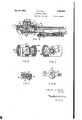
- Figure 1 is a top plan view of the electrode holder looking in the direction of arrow I, Figure 2;
- Figure 2 is a side elevation looking in the direction of arrow 2, Figure 1;
- Figure 3 is a bottom plan view looking in the direction of arrow 3, Figure 2;
- Figure 4 is a section taken on line 4-4, Figure 1;
- Figure 5 is a view partly in section and partly in plan looking in the direction of arrows 5 Figure 4;
- Figure 6 is a section taken on line 66, Figure 4;
- Figure? is a transverse section taken on line 1-1, Figure 4;
- Figure 8 is a bottom plan view of the clamping nut, a portion thereof being broken away to better disclose the construction.
- reference numeral l0 designates the metal portion of the handle. This portion is tubular and serves to receive the end H of the conductor that carries the welding current. A plurality of screws l2 pass through threaded openings in the wall of the handle and manner shown quite clearly in Figure 4.
- the other end of the handle is provided with a flattened portion l3, whose upper surface has been designated by reference numeral [4 and will be referred to as a friction surface.
- a pivot bolt 15 extends through an opening in the flattened end l3 and projects perpendicularly from the friction surface. This bolt is threaded as indicated at I.
- the clampinghead which has been designated in its entirety by reference number I1, comprises a lower jaw II and an upper jaw I9.
- these jaws are integrally connected at 2
- Jaw I 8 is provided with an opening 2
- Pivot bolt l5 extends upwardly a considerable distance above the upper surface of jaw is and a clamping nut 2'! is operatively connected with the upper end of the bolt.
- Theclamping nut has a central recess 28 of substantially the same size as opening 22 and is provided about its outer surface with an annular groove 2d. The lower wall of the groove forms a flange 30.
- a short piece of metal 3i that projects into the groove 29 of the-nut and holds of insulator 38 are arcuate, being curved about the center of the clamping bolt it; this permits the clamping head to be rotated through an angle of 360 degrees and more particularly through an angle of 180 degrees so that the open end of the clamping head can be turned outwardly as shown in Figure d or rotated so as to bring the open end inwardly.
- This is of importance in employing a very small electrode and the end where it is clamped can thus be brought to the outside into the position shown in Figure 1.
- interlock between nut 21 and jaw 69 in addition to making it possible to separate the jaws in case they should be strained so as to acquire a permanent set, is to prevent the nut 21 from becoming accidentally separated from the tool and lost.
- a tubular member 33 of fiber, hard rubber or any other suitable electrical insulating material usually also has the property of being a good heat insulator.
- the flattened end portion is is covered along its sides, bottoms and end by an insulatin member 3d.
- the insulating member 33 is held in place by means of one or more screws 35, whose heads are countersunk and covered with a plug 35 of insulating material and insulator 3d is similarly held in place by means of a screw 3?.
- clamping head is enclosed in abox-like insulator at that extends downwardly over the sides and ends.
- the sides of this insulator are provided The shown as plane surfaces but it is to be understood that frusto-conical or spherical surfaces can be employed wherever such a construction is believed to be preferable.
- the electrode 66 can be moved from the full line to the dotted line posi tion.
- the full line position is suitable for use when making a horizontal weld as, for example, when the parts are supported on a table.
- the electrode is moved into the broken line positionand projects practically parallel with the axis of the handle. It is evident, of course, that any other position that mightbe found desirable can be obtained by rotating the clamping head about the pivot bolt.
- the insulator 38 is attached to the jaw I9 by one or more screws fill. Due to the box-like insulator 38,- it is possible to employ jaws l8 and i9 that are entirely separated because they will be held in proper alignment by means of the enclosing insulator. Although two separate jaws may be employed, a construction like that shown in the drawings is recommended as preferable.
- the nut 27 is enclosed in an insulator 4! which entirely covers the exposed outer surface and extends over the wings 42 so that the holdemay be convenientlyoperated without the necessity of the operator coming in contact with any electrically chargedsurface.
- connection between nut 21 and jaw it makes it possible not only to move them towards each other, but also to spread them apart-should occasion require.
- the latter is useful in cases where, due to some accidental pressure, the jaws have received a permanent set so as to prevent them from moving apart as far as desired due to their spring action and where the jaws are hingedly' connected the interconnection between the nut and the upper jaw member is of considerable importance.
- An electrode holder comprising a handle having one end provided with afriction surface, a-clamping-head rctatably connected with the handle by means of a pivot pin projecting from the friction surface, the clamping head comprising two jaws, mean for holding the jaws in spaced relation, means for urging the surface of one jaw against the friction surface with sulficient force to resist accidental rotation, means for holding the jaws in alignment, and means for simultaneously urging one jaw towards the other jaw and towards the friction surface.
- An electrode holder comprising a handle having one end provided with means for effecting a connection with an electric cable and the other with a friction surface, a bolt connected with the handle and projecting from the friction surface, a clamping head having two spaced jaws, one jaw having a surface resting on the friction surface, the jaws having aligned openings of different size, the opening in the jaw adjacent the friction surface being of a size to receive the bolt, the hole in the other jaw being of sufficient size to receive a nut, a nut operatively connected with the bolt, resilient means between the nut and the lower jaw, and a second nut operatively connected with the bolt for engagement with the upper surface of the upper jaw, the first mentioned nut serving to secure the clamping head to the handle and the second nut serving to urge the upper jaw towards the lower jaw and the clamping head against the friction surface.
- a welding electrode holder comprising a handlehaving one end provided with a friction surface, a clamping head having two spaced jaws provided with complementary electrode engaging surfaces, means comprising a bolt for pivotall'y attaching the clamping head to the handle, means comprising a resilient member and the bolt for urging the clamping head against the friction surface to effect a frictional resistance against relative rotary movement about the pivot,
- a welding electrode holder comprising a handle having one end provided with a friction surface, a bolt projecting upwardly from the friction surface, a clamping head having two vertically spaced jaws provided with complementary electrode engaging surfaces, the lower jaw resting on the friction surface, the jaws having axially aligned holes through both of which the bolt extends, the hole in the jaw in contact with.
- the friction surface being smaller than the hole in the other jaw, a nut operatively connected with the bolt and positioned to exert pressure on the lower jaw for urging it against the friction surface, a resilient element positioned between the nut and the upper surface of the lower jaw, and another nut operatively connected with the bolt and positioned for engagement with the upper surface of the upper jaw to urge it towards the lower jaw to clamp an electrode between them.
- a welding electrode holder comprising a handle having one end provided with a friction surface, a bolt projecting upwardly from the fricnut operatively connected with the bolt and posithrough the openings in the jaws, and means comprising a nut operatively associated with the bolt and the upper jaw for urging it towards the lower jaw to clamp anelectrode therebetween.
- a welding electrode holder comprising a. handle having one end provided with a friction surface, a bolt projecting upwardly from the friction surface, a clamping head having two vertically spaced jaws provided with complementary electrode engaging surfaces, the lower surface of the lower jaw being in contact with the friction surface, the jaws having axially aligned holes through both of which the bolt extends, the hole in the lower jaw being smaller than the hole in the upper jaw, a nut on the bolt in position to exert pressure on the lower jaw urging it against the friction surface, and another nut operatively connected with the bolt and positioned for engagement with the upper surface of the upper jaw to urge it'towards thiQlower jaw to clamp an electrode between them.
- An electrode holder comprising a handle having one end provided with a friction surface, a clamping head comprising two relatively movable jaws, one of which has one surface contacting the friction surface of the handle, means for holding the jaws in alignment, the two jaws having axially aligned openings, the handle having an opening, a bolt passing through all three openings, one endv of the bolt being provided with threads, the bolt having an annular shoulder facing the handle, a spring surrounding the bolt with one end in operative engagement with the shoulder, the other end facing the friction surface, the spring and the bolt comprising means for urging one of the jaws against the friction surface of the handle, and means for moving the adjacent surfaces of the jaws towards each other to clamp an electrode therebetween, said means comprising a member in operative engagement with the theads on the bolt.
Landscapes
- Engineering & Computer Science (AREA)
- Physics & Mathematics (AREA)
- Plasma & Fusion (AREA)
- Mechanical Engineering (AREA)
- Gripping Jigs, Holding Jigs, And Positioning Jigs (AREA)
Description
y 1943- H. H. HALL 2,324,924
. ELECTRODE HOLDER Filed Feb. 13, 1943 2 Sheets-Sheet 1 HARVEY H. HALL, F|6-3- INVENTOR.
July 20, 1943. H H, HALL 2,324,924
ELECTRODE HOLDER Filed Feb. 13, 1943 2 Sheets-Sheet 2 FIG. 7. FIGS.
HARVEY H. HALL,
INVENTOR.
@M Ma Patented July 20, 1943 UNITED STATES PATENT OFFICE ELECTRODE HOLDER Harvey H. Hall, Denver, 0010. Application February 1 3, 1943, Serial No. 475,841
7 Claims. (Cl. 219-8) This invention relates to improvements in electrode holders of the type employed in connection with arc welding.
Arc welding is very extensively employed in industry wherevertwo pieces of metal are to be joined. During the process of arc welding an electrode formed from iron or other metal to be employed in the welding operation is supported from a suitable holder and moved along the seam to be welded. The material to be welded and the electrode are connected to opposite poles-of a suitable electric supply.
For the purpose of supporting such electrodes during the welding operation, many different holders have been invented, some of which are widely employed.
It is the object of this invenion to produce an electrode holder of an improved construction that shall have several advantages over those generally employed and which shall facilitate the operation of arc welding.
One object of this invention is to produce an electrode holder of such construction that it shall not require any special wrenches for its operation.
A further object is to produce an electrode holder of comparatively light weight and of such simple construction that it can be manufactured at a low price.
A further object is to produce an electrode holder that will not readily heat up during the operation;
A still further object is to produce an electrode holder in which the electrode can be adjusted about a pivot so as to bring it into the most desirable position for either sidewise or up and down-motion, and which can also be adjusted to the most desirable angle for welding parts supported on a table or forrnipefa horizontal surface.
Another object is to produce an electrode holder in which an increased contact area is provided between the cable and the-handle so as to reduce the resistance at this point and thereby also reduce the heat generated. And a sill further object is to produce an electrode holder of such construction that it can be completely insulated both electrically and against the conduction of heat.
The above and other objects that may become apparent as this description proceeds are attained by means of a construction and an arrangement of parts that will now be described in detail, and for this purpose reference will th invention has been illustrated in its preferred form, and in which: 7
Figure 1 is a top plan view of the electrode holder looking in the direction of arrow I, Figure 2;
Figure 2 is a side elevation looking in the direction of arrow 2, Figure 1;
Figure 3 is a bottom plan view looking in the direction of arrow 3, Figure 2;
Figure 4 is a section taken on line 4-4, Figure 1;
Figure 5 is a view partly in section and partly in plan looking in the direction of arrows 5 Figure 4;
Figure 6 is a section taken on line 66, Figure 4;
Figure? is a transverse section taken on line 1-1, Figure 4; and
Figure 8 is a bottom plan view of the clamping nut, a portion thereof being broken away to better disclose the construction.
In the drawings reference numeral l0 designates the metal portion of the handle. This portion is tubular and serves to receive the end H of the conductor that carries the welding current. A plurality of screws l2 pass through threaded openings in the wall of the handle and manner shown quite clearly in Figure 4. The other end of the handle is provided with a flattened portion l3, whose upper surface has been designated by reference numeral [4 and will be referred to as a friction surface. A pivot bolt 15 extends through an opening in the flattened end l3 and projects perpendicularly from the friction surface. This bolt is threaded as indicated at I.
The clampinghead, which has been designated in its entirety by reference number I1, comprises a lower jaw II and an upper jaw I9. In the embodiment shown these jaws are integrally connected at 2|, but it is to be understood that they may be connected by means of a hinge or that they may even be two entirely separate members. Jaw I 8 is provided with an opening 2|. for the reception of the corresponding portion of the pivot bolt and jaw I9 is provided with an opening 22,-which is larger than opening M. The
clamping head is secured by means of a nut 23,
and a lock nut 24. An ordinary washer 25 is positioned adjacent the upper surface of jaw l8 and separating this from the nut 23 is a spring washer 26. By adjusting the nuts 23 and 24, the clamping head is urged against the friction areenclosed in insulating material.
surface with sumcient force to produce a frictional resistancesufficient to hold the head against accidental rotation about the pivot bolt. The reason opening 22 is larger than opening 2! is apparent, because the nuts 23 and 24 are positioned therein. Pivot bolt l5 extends upwardly a considerable distance above the upper surface of jaw is and a clamping nut 2'! is operatively connected with the upper end of the bolt. Theclamping nut has a central recess 28 of substantially the same size as opening 22 and is provided about its outer surface with an annular groove 2d. The lower wall of the groove forms a flange 30. Secured to the upper surface of jaw I9 is a short piece of metal 3i that projects into the groove 29 of the-nut and holds of insulator 38 are arcuate, being curved about the center of the clamping bolt it; this permits the clamping head to be rotated through an angle of 360 degrees and more particularly through an angle of 180 degrees so that the open end of the clamping head can be turned outwardly as shown in Figure d or rotated so as to bring the open end inwardly. This is of importance in employing a very small electrode and the end where it is clamped can thus be brought to the outside into the position shown in Figure 1.
In the drawings the friction surface It and the cooperating surface of the jaw ill have been clamping an electrodein position. By means of the nut Z'l, whose lower end engages the upper surface of jaw, l9, the upper jaw can be forced downwardly-against an electrode positioned in one of the openings 32. When nut 27 is rotated in a direction to move it upwardly on the pivot bolt, it engages the lower surface of the part 3i and raises jaw l9 upwardly. The purpose of this.
interlock between nut 21 and jaw 69, in addition to making it possible to separate the jaws in case they should be strained so as to acquire a permanent set, is to prevent the nut 21 from becoming accidentally separated from the tool and lost.
In the above description the metal parts only have been referred to, but it will be observed from the drawings that the several metallic parts Handle M9 is enclosed in a tubular member 33 of fiber, hard rubber or any other suitable electrical insulating material. This insulating material usually also has the property of being a good heat insulator. The flattened end portion is is covered along its sides, bottoms and end by an insulatin member 3d. The insulating member 33 is held in place by means of one or more screws 35, whose heads are countersunk and covered with a plug 35 of insulating material and insulator 3d is similarly held in place by means of a screw 3?. clamping head is enclosed in abox-like insulator at that extends downwardly over the sides and ends. The sides of this insulator are provided The shown as plane surfaces but it is to be understood that frusto-conical or spherical surfaces can be employed wherever such a construction is believed to be preferable.
Referring now more particularly to Figure 1, it will be observed that the electrode 66 can be moved from the full line to the dotted line posi tion. The full line position is suitable for use when making a horizontal weld as, for example, when the parts are supported on a table. When a vertical surface is to be welded, either along a horizontal or a vertical line, the electrode is moved into the broken line positionand projects practically parallel with the axis of the handle. It is evident, of course, that any other position that mightbe found desirable can be obtained by rotating the clamping head about the pivot bolt.
Attention is called in particular to the feature of the construction shown in Figure 4, in which the clamping head is held against the friction surface by means of the nuts and spring washer, whose adjustments remain constant, and to the fact that the upper jaw is moved independently This construction assures that the clamping head will never become loose so as to shift its position in an accidental manner and it also assures that the two jaws will not become accidentally separated. The inter-.
with openings 39, through which the electrodes may be inserted into the depressions 32 in the clamping jaws. The insulator 38 is attached to the jaw I9 by one or more screws fill. Due to the box-like insulator 38,- it is possible to employ jaws l8 and i9 that are entirely separated because they will be held in proper alignment by means of the enclosing insulator. Although two separate jaws may be employed, a construction like that shown in the drawings is recommended as preferable.
The nut 27 is enclosed in an insulator 4! which entirely covers the exposed outer surface and extends over the wings 42 so that the holdemay be convenientlyoperated without the necessity of the operator coming in contact with any electrically chargedsurface.
Attention is called to the fact that the ends 4.3
connection between nut 21 and jaw it makes it possible not only to move them towards each other, but also to spread them apart-should occasion require. The latter is useful in cases where, due to some accidental pressure, the jaws have received a permanent set so as to prevent them from moving apart as far as desired due to their spring action and where the jaws are hingedly' connected the interconnection between the nut and the upper jaw member is of considerable importance.
By positioning the nuts 23 and 26in an opening in the upper jaw, a neat construction is obtained.
It would, of course, be possible to position the nuts in an opening in insulating member 35 and to permanently attach the bolt to the wall of opening 2i but this is not considered to be a practical construction. It is to be understood, however, that applicant desires protection against obvious modifications by means of which the same results are obtained by substantially the same or equivalent means. I
Wherever the terms upper and lower are em ployed in connection with the description; or in the claims, the relationship of parts shown in Figure 4 is referred to. Since the tool can be rotated about its axis these terms must, of course, be construed in relation to a certain position.
Having described the invention what is claimed as new is:
1. An electrode holder comprising a handle having one end provided with afriction surface, a-clamping-head rctatably connected with the handle by means of a pivot pin projecting from the friction surface, the clamping head comprising two jaws, mean for holding the jaws in spaced relation, means for urging the surface of one jaw against the friction surface with sulficient force to resist accidental rotation, means for holding the jaws in alignment, and means for simultaneously urging one jaw towards the other jaw and towards the friction surface.
2. An electrode holder comprising a handle having one end provided with means for effecting a connection with an electric cable and the other with a friction surface, a bolt connected with the handle and projecting from the friction surface, a clamping head having two spaced jaws, one jaw having a surface resting on the friction surface, the jaws having aligned openings of different size, the opening in the jaw adjacent the friction surface being of a size to receive the bolt, the hole in the other jaw being of sufficient size to receive a nut, a nut operatively connected with the bolt, resilient means between the nut and the lower jaw, and a second nut operatively connected with the bolt for engagement with the upper surface of the upper jaw, the first mentioned nut serving to secure the clamping head to the handle and the second nut serving to urge the upper jaw towards the lower jaw and the clamping head against the friction surface.
3. A welding electrode holder comprising a handlehaving one end provided with a friction surface, a clamping head having two spaced jaws provided with complementary electrode engaging surfaces, means comprising a bolt for pivotall'y attaching the clamping head to the handle, means comprising a resilient member and the bolt for urging the clamping head against the friction surface to effect a frictional resistance against relative rotary movement about the pivot,
. the jaws having aligned openings concentric with the pivot, a bolt having its lower end in cooperative engagement with that portion of the handle having the friction surface and projecting 5. A welding electrode holder comprising a handle having one end provided with a friction surface, a bolt projecting upwardly from the friction surface, a clamping head having two vertically spaced jaws provided with complementary electrode engaging surfaces, the lower jaw resting on the friction surface, the jaws having axially aligned holes through both of which the bolt extends, the hole in the jaw in contact with.
the friction surface being smaller than the hole in the other jaw, a nut operatively connected with the bolt and positioned to exert pressure on the lower jaw for urging it against the friction surface, a resilient element positioned between the nut and the upper surface of the lower jaw, and another nut operatively connected with the bolt and positioned for engagement with the upper surface of the upper jaw to urge it towards the lower jaw to clamp an electrode between them.
6. A welding electrode holder comprising a handle having one end provided with a friction surface, a bolt projecting upwardly from the fricnut operatively connected with the bolt and posithrough the openings in the jaws, and means comprising a nut operatively associated with the bolt and the upper jaw for urging it towards the lower jaw to clamp anelectrode therebetween.
4. A welding electrode holder comprising a. handle having one end provided with a friction surface, a bolt projecting upwardly from the friction surface, a clamping head having two vertically spaced jaws provided with complementary electrode engaging surfaces, the lower surface of the lower jaw being in contact with the friction surface, the jaws having axially aligned holes through both of which the bolt extends, the hole in the lower jaw being smaller than the hole in the upper jaw, a nut on the bolt in position to exert pressure on the lower jaw urging it against the friction surface, and another nut operatively connected with the bolt and positioned for engagement with the upper surface of the upper jaw to urge it'towards thiQlower jaw to clamp an electrode between them.
tioned for engagement with the outer surface of the upper jaw to urge it towards the lower jaw to clamp an electrode between them, and means connected with the upper jaw and operatively engaging the last named nut to resist upward movement of the nut relative to the jaw whereby a force can be exerted thereon to move it away from the lower jaw.
7. An electrode holder comprising a handle having one end provided with a friction surface, a clamping head comprising two relatively movable jaws, one of which has one surface contacting the friction surface of the handle, means for holding the jaws in alignment, the two jaws having axially aligned openings, the handle having an opening, a bolt passing through all three openings, one endv of the bolt being provided with threads, the bolt having an annular shoulder facing the handle, a spring surrounding the bolt with one end in operative engagement with the shoulder, the other end facing the friction surface, the spring and the bolt comprising means for urging one of the jaws against the friction surface of the handle, and means for moving the adjacent surfaces of the jaws towards each other to clamp an electrode therebetween, said means comprising a member in operative engagement with the theads on the bolt.
HARVEY H. HALL.
Priority Applications (1)
| Application Number | Priority Date | Filing Date | Title |
|---|---|---|---|
| US475841A US2324924A (en) | 1943-02-13 | 1943-02-13 | Electrode holder |
Applications Claiming Priority (1)
| Application Number | Priority Date | Filing Date | Title |
|---|---|---|---|
| US475841A US2324924A (en) | 1943-02-13 | 1943-02-13 | Electrode holder |
Publications (1)
| Publication Number | Publication Date |
|---|---|
| US2324924A true US2324924A (en) | 1943-07-20 |
Family
ID=23889374
Family Applications (1)
| Application Number | Title | Priority Date | Filing Date |
|---|---|---|---|
| US475841A Expired - Lifetime US2324924A (en) | 1943-02-13 | 1943-02-13 | Electrode holder |
Country Status (1)
| Country | Link |
|---|---|
| US (1) | US2324924A (en) |
Cited By (3)
| Publication number | Priority date | Publication date | Assignee | Title |
|---|---|---|---|---|
| US6444951B1 (en) | 2001-02-20 | 2002-09-03 | Newport News Shipbuilding | Welding rod extending assembly for attachment with electrode holder |
| US20130119041A1 (en) * | 2011-01-05 | 2013-05-16 | Jeff Humenik | Insulated electrode cover for a welding electrode holder |
| US8729428B1 (en) * | 2008-10-23 | 2014-05-20 | Patrick Malloy | Welding rod expander assembly |
-
1943
- 1943-02-13 US US475841A patent/US2324924A/en not_active Expired - Lifetime
Cited By (4)
| Publication number | Priority date | Publication date | Assignee | Title |
|---|---|---|---|---|
| US6444951B1 (en) | 2001-02-20 | 2002-09-03 | Newport News Shipbuilding | Welding rod extending assembly for attachment with electrode holder |
| US8729428B1 (en) * | 2008-10-23 | 2014-05-20 | Patrick Malloy | Welding rod expander assembly |
| US20130119041A1 (en) * | 2011-01-05 | 2013-05-16 | Jeff Humenik | Insulated electrode cover for a welding electrode holder |
| US12005534B2 (en) * | 2011-01-05 | 2024-06-11 | Constellation Energy Generation, Llc | Insulated electrode cover for a welding electrode holder |
Similar Documents
| Publication | Publication Date | Title |
|---|---|---|
| US2420895A (en) | Ground clamp | |
| US5046958A (en) | Welding ground clamp | |
| US2324924A (en) | Electrode holder | |
| US3134883A (en) | Electrode for electrical resistance heating tool | |
| US1964511A (en) | Connecter clamp | |
| US1865003A (en) | Electric welding tong | |
| US2470854A (en) | Heating tool | |
| US2049312A (en) | Welding apparatus | |
| US2558083A (en) | Controller handle for electrode holders | |
| US2375836A (en) | Electrode holder | |
| US2765395A (en) | Electrical connector for welding and riveting | |
| US2401523A (en) | Welding electrode holder | |
| US2347880A (en) | Electrode holder | |
| US3408472A (en) | Welding tool | |
| US2280747A (en) | Socket | |
| US2283162A (en) | Electrode holder | |
| US1677306A (en) | Electric welding tongs | |
| US3013143A (en) | Welding contactor | |
| US2002291A (en) | Connecter element | |
| US2128799A (en) | Electrode holder | |
| US2922027A (en) | Swing head electrode holder | |
| US2343998A (en) | Welding apparatus | |
| US1732441A (en) | Electrode holder | |
| US2312763A (en) | Welding rod holder | |
| US2393742A (en) | Welding electrode holder |