US232012A - duryee - Google Patents
duryee Download PDFInfo
- Publication number
- US232012A US232012A US232012DA US232012A US 232012 A US232012 A US 232012A US 232012D A US232012D A US 232012DA US 232012 A US232012 A US 232012A
- Authority
- US
- United States
- Prior art keywords
- furnace
- pipe
- blast
- air
- hearth
- Prior art date
- Legal status (The legal status is an assumption and is not a legal conclusion. Google has not performed a legal analysis and makes no representation as to the accuracy of the status listed.)
- Expired - Lifetime
Links
- 239000000446 fuel Substances 0.000 description 9
- 239000007789 gas Substances 0.000 description 8
- 239000007788 liquid Substances 0.000 description 8
- 239000004215 Carbon black (E152) Substances 0.000 description 2
- 238000010276 construction Methods 0.000 description 2
- 229930195733 hydrocarbon Natural products 0.000 description 2
- 150000002430 hydrocarbons Chemical class 0.000 description 2
- 101000580317 Homo sapiens RNA 3'-terminal phosphate cyclase-like protein Proteins 0.000 description 1
- 235000019738 Limestone Nutrition 0.000 description 1
- 102100027566 RNA 3'-terminal phosphate cyclase-like protein Human genes 0.000 description 1
- 230000001174 ascending effect Effects 0.000 description 1
- 239000011449 brick Substances 0.000 description 1
- 239000004927 clay Substances 0.000 description 1
- 150000001875 compounds Chemical class 0.000 description 1
- 238000001816 cooling Methods 0.000 description 1
- 238000010438 heat treatment Methods 0.000 description 1
- 239000006028 limestone Substances 0.000 description 1
- 239000000463 material Substances 0.000 description 1
- 239000003208 petroleum Substances 0.000 description 1
- 239000011347 resin Substances 0.000 description 1
- 229920005989 resin Polymers 0.000 description 1
- 239000007921 spray Substances 0.000 description 1
Images

Classifications
-
- F—MECHANICAL ENGINEERING; LIGHTING; HEATING; WEAPONS; BLASTING
- F27—FURNACES; KILNS; OVENS; RETORTS
- F27B—FURNACES, KILNS, OVENS OR RETORTS IN GENERAL; OPEN SINTERING OR LIKE APPARATUS
- F27B17/00—Furnaces of a kind not covered by any of groups F27B1/00 - F27B15/00
- F27B17/0016—Chamber type furnaces
- F27B17/0041—Chamber type furnaces specially adapted for burning bricks or pottery
Definitions
- the subject of my invention is a device applicable to pottery-kilns, en ameling-kilns, fretkilns, and the like, also to kilns for burning 1o tiles, fire-brick, and other wares.
- It consists of an apparatus by which a combined blast of air and liquid fuel or gas can be applied in a jet through the flame of an ordinary fuelfurnace.
- These heating devices are arranged at suitableintervals around the oven, the air-blast and the liquid fuel or'gas being each supplied through an annular pipe surrounding the oven.
- the blast-nozzle constitutes a retort within which inflammable gas is generated from the oil or other liquid fuel.
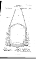
- FIG. 1 is an elevation of a pottery-furnace illustrating my invention.
- Fig. 2 is a vertical longitudinal section of the same.
- Fig. 3 is a longitudinal section of the blast-nozzle on a larger scale.
- 0 A represents the oven; B, the stack; O, the hearth or receptacle for the wares to be burned or baked.
- D is a door of usual construction.
- E E E represent fire-places or fuelfurnaces F, the furnace-door, and G the grates thereof.
- J J J J are pipes descending from the annular pipe H for conveying the blast to the nozzles N.
- the said pipes J are controlled by cocks K.
- 4.0 L is an annular pipe for conducting petroleum or other hydrocarbon or any suitable liquid fuel, which may be resin or other fusible matter in a liquid state, from a reservoir, M; or this may be simply a pipe conducting 4 5 gas from a natural or artificial source of sup ply.
- P P are pipes for the liquid fuel, trapped as shown at O, and controlled by cocks or valves Q to regulate the flow.
- the construction of the blast-nozzle N is more clearly shown in Fig. 3. It is formed of two concentric jetpipes, the inner one formed of the horizontal termination I? of the oil-pipe P, and the outer one of the horizontal end of the air-pipe J.
- the nozzle N is itself formed of fire-clay or surrounded with this or other suitable material.
- the nozzle thu constitutes a generating-bunier, being exposed to the heat of the fuel in the furnace E.
- the sides of the hearth or receptacle 0, where the goods are placed for burning, are extended for a sufflcient height to conduct the flame to the upper parts of the oven.
- blow-pipe jet is introduced in every furnace in a horizontal direction, composed of a combination of atmospheric air and hydrocarbon vapor or gas, which, impinging upon the flame in the fuelfurnace E, drives a blow-pipe flame of intense heat inward beneath the hearth O.
- the said blow-pipe flames being thus driven inward from every direction toward the center, unite beneath the hearth, and the heat is carried up in a very effective manner around the sides thereof, so as to thoroughly bake the wares in the upper part of the oven.
- My invention thus constitutes a combined kiln for alternate use in baking and cooling the wares.
- a series or range of converging nozzles, N surrounding the kiln horizontally and consisting of two pipes-one for conducting liquid fuel or gas and the other for an air-blastin combination with a fuel-furnace located below the level of the nozzles, so as to cause the blast therefrom to produce converging blow-pipe flames, and with a baking-hearth elevated to receive the blow-pipe flames beneath it, and constructed with vertical walls to distribute the heat upwardly and equalize the same throughout the oven.
Landscapes
- Engineering & Computer Science (AREA)
- Mechanical Engineering (AREA)
- General Engineering & Computer Science (AREA)
- Furnace Details (AREA)
Description
2 Sheets-Sheet 1. G. D URYEE.
Pottery Furnace;
No. 232,012. ented Sept. 7,1880.
' 2 Sheets- Sheet 2; G. DURYEE.
Pottery Furnace.
No. 232,012. Patented Sept. 7,1880.
N. PEYERS, PHOTO-LITHOGRAPNBL WA$HINGTON, D c.
UNTTED STATES GEORGE DU tYEE, OF NFAV YORK, N.
Y., ASSIGNOR OF ONE-HALF OF HIS RIGHT TO JOHN H. BREWER, OF TRENTON, NEV JERSEY.
POTTERY-FU RNAC E.
SPECIFICATION forming part of Letters Patent No. 232,012, dated September 7, 1880.
Application filed December 1, 1879.
To all whom it may concern:
Be it known that I, GEORGE DURYEE,M.D., of New York, in the county and State of New York, have invented a new and useful Improvement in Pottery-Furnaces, of which the following is a specification.
The subject of my invention is a device applicable to pottery-kilns, en ameling-kilns, fretkilns, and the like, also to kilns for burning 1o tiles, fire-brick, and other wares.
It consists of an apparatus by which a combined blast of air and liquid fuel or gas can be applied in a jet through the flame of an ordinary fuelfurnace. These heating devices are arranged at suitableintervals around the oven, the air-blast and the liquid fuel or'gas being each supplied through an annular pipe surrounding the oven. The blast-nozzle constitutes a retort within which inflammable gas is generated from the oil or other liquid fuel.
In order that my invention may be fully understood, I will proceed to describe it with reference to the accompanying drawings, in which 2 5 Figure 1 is an elevation of a pottery-furnace illustrating my invention. Fig. 2 is a vertical longitudinal section of the same. Fig. 3 is a longitudinal section of the blast-nozzle on a larger scale.
0 A represents the oven; B, the stack; O, the hearth or receptacle for the wares to be burned or baked. D is a door of usual construction. E E E represent fire-places or fuelfurnaces F, the furnace-door, and G the grates thereof.
His an annular air-pipe surrounding the furnace and conducting the blast from a fan, I. J J J are pipes descending from the annular pipe H for conveying the blast to the nozzles N. The said pipes J are controlled by cocks K.
4.0 L is an annular pipe for conducting petroleum or other hydrocarbon or any suitable liquid fuel, which may be resin or other fusible matter in a liquid state, from a reservoir, M; or this may be simply a pipe conducting 4 5 gas from a natural or artificial source of sup ply.
I? P P are pipes for the liquid fuel, trapped as shown at O, and controlled by cocks or valves Q to regulate the flow.
The construction of the blast-nozzle N is more clearly shown in Fig. 3. It is formed of two concentric jetpipes, the inner one formed of the horizontal termination I? of the oil-pipe P, and the outer one of the horizontal end of the air-pipe J. The nozzle N is itself formed of fire-clay or surrounded with this or other suitable material. The nozzle thu constitutes a generating-bunier, being exposed to the heat of the fuel in the furnace E.
The sides of the hearth or receptacle 0, where the goods are placed for burning, are extended for a sufflcient height to conduct the flame to the upper parts of the oven.
In operation, fire is made with any suitable fuel on the grates G, and the air-blast and oiljet being turned on, a blow-pipe jet is introduced in every furnace in a horizontal direction, composed of a combination of atmospheric air and hydrocarbon vapor or gas, which, impinging upon the flame in the fuelfurnace E, drives a blow-pipe flame of intense heat inward beneath the hearth O. The said blow-pipe flames, being thus driven inward from every direction toward the center, unite beneath the hearth, and the heat is carried up in a very effective manner around the sides thereof, so as to thoroughly bake the wares in the upper part of the oven.
R It It represent outlets for the gases through the ovenroof.
As soon as the wares are thoroughly baked the fires are drawn, the flow of oil through the pipes P stopped, and the blast being continued, the furnace and its contents are cooled as rapidly as desirable, thus eflectin g a great saving of time required to work an entire charge and replace it with a new one. My invention thus constitutes a combined kiln for alternate use in baking and cooling the wares.
I am aware that it has been proposed to use a compound nozzle for the projection upon the flame of mingle'treams of oil and steam. I am also aware that jets of air and oil have been combined but I am not aware that such streams of liquid fuel have been so applied to 5 the flame of a fuel-furnace as to produce a blow-pipe flame.
I am also aware that a stream of mingled air and oil has been introduced into a furnace, so as to be projected in the form of spray upon 10o limestone at a red heat. I am also aware that such streams of oil and air have been introduced so as to impinge upon and even to pass over the surface of the hearth but I am not aware of any device where a furnace has been constructed so that the grate shall be at or near thebottom of the kiln, the flames from which furnace pass upward to the potteryhearth and come in contact, when inline with such hearth, with a stream of mingled air and oil or gas projected against said ascending flames, so as to produce blow-pipe flames, which are blown upon and around the pottery-hearth, and thereby insure the rapid baking of articles thereupon.
Having thus described my invention, the following is what I claim as new therein and desire to secure by Letters Patent:
1. In a pottery or other kiln, a series or range of converging nozzles, N, surrounding the kiln horizontally and consisting of two pipes-one for conducting liquid fuel or gas and the other for an air-blastin combination with a fuel-furnace located below the level of the nozzles, so as to cause the blast therefrom to produce converging blow-pipe flames, and with a baking-hearth elevated to receive the blow-pipe flames beneath it, and constructed with vertical walls to distribute the heat upwardly and equalize the same throughout the oven.
2. The combination of the annular blastpipe H, the annular oilpipe L, descending pipes J P, the nozzles N, and furnace E below the level of said nozzles, with a crockery-oven or other kiln having the sides of the hearth extendin g upward for the purpose of conducting the flames to the upper part of the oven or kiln, substantially as set forth.
GEORGE DURYEE, M. D.
WVitnesses H. E. KNIGHT, OOTAVIUS KNIGHT.
Publications (1)
| Publication Number | Publication Date |
|---|---|
| US232012A true US232012A (en) | 1880-09-07 |
Family
ID=2301382
Family Applications (1)
| Application Number | Title | Priority Date | Filing Date |
|---|---|---|---|
| US232012D Expired - Lifetime US232012A (en) | duryee |
Country Status (1)
| Country | Link |
|---|---|
| US (1) | US232012A (en) |
-
0
- US US232012D patent/US232012A/en not_active Expired - Lifetime
Similar Documents
| Publication | Publication Date | Title |
|---|---|---|
| US232012A (en) | duryee | |
| US1271364A (en) | Furnace. | |
| US726861A (en) | Furnace for roasting and smelting ores. | |
| US187243A (en) | Improvement in furnaces for brick-kilns | |
| US297638A (en) | Method of using natural gas as a fuel | |
| US347875A (en) | Furnace-forge for welding and forging iron | |
| US419406A (en) | James h | |
| US883260A (en) | Fluid-fuel furnace. | |
| US229525A (en) | George duryee | |
| US343061A (en) | Air-blast-heating oven | |
| US111288A (en) | Atid blast heating | |
| US156564A (en) | Improvement in metallurgy gas-furnaces | |
| US291386A (en) | Moeg-an | |
| US272378A (en) | Chaeles j | |
| US131804A (en) | Improvement in apparatus for burning liquid fuel to heat furnaces | |
| US1357494A (en) | Forced rotary-draft furnace | |
| US633035A (en) | Smelting-furnace. | |
| US446971A (en) | And smelting furnace | |
| US854005A (en) | Means or apparatus for burning or fixing the colors upon printed or decorated tiles, glass &c. | |
| US1734387A (en) | Ring-flow reverberatory furnace | |
| US341506A (en) | Apparatus for manufacturing gas | |
| US336485A (en) | Eobeet w | |
| US407000A (en) | Charles j | |
| US183140A (en) | Improvement in pottery-kilns | |
| US405935A (en) | Walter b |