US2314886A - Punch press - Google Patents
Punch press Download PDFInfo
- Publication number
- US2314886A US2314886A US393040A US39304041A US2314886A US 2314886 A US2314886 A US 2314886A US 393040 A US393040 A US 393040A US 39304041 A US39304041 A US 39304041A US 2314886 A US2314886 A US 2314886A
- Authority
- US
- United States
- Prior art keywords
- leaf
- punch
- press
- plate holder
- punch plate
- Prior art date
- Legal status (The legal status is an assumption and is not a legal conclusion. Google has not performed a legal analysis and makes no representation as to the accuracy of the status listed.)
- Expired - Lifetime
Links
Images


Classifications
-
- B—PERFORMING OPERATIONS; TRANSPORTING
- B21—MECHANICAL METAL-WORKING WITHOUT ESSENTIALLY REMOVING MATERIAL; PUNCHING METAL
- B21D—WORKING OR PROCESSING OF SHEET METAL OR METAL TUBES, RODS OR PROFILES WITHOUT ESSENTIALLY REMOVING MATERIAL; PUNCHING METAL
- B21D28/00—Shaping by press-cutting; Perforating
-
- Y—GENERAL TAGGING OF NEW TECHNOLOGICAL DEVELOPMENTS; GENERAL TAGGING OF CROSS-SECTIONAL TECHNOLOGIES SPANNING OVER SEVERAL SECTIONS OF THE IPC; TECHNICAL SUBJECTS COVERED BY FORMER USPC CROSS-REFERENCE ART COLLECTIONS [XRACs] AND DIGESTS
- Y10—TECHNICAL SUBJECTS COVERED BY FORMER USPC
- Y10T—TECHNICAL SUBJECTS COVERED BY FORMER US CLASSIFICATION
- Y10T83/00—Cutting
- Y10T83/869—Means to drive or to guide tool
- Y10T83/8717—By deforming resilient tool or tool support
-
- Y—GENERAL TAGGING OF NEW TECHNOLOGICAL DEVELOPMENTS; GENERAL TAGGING OF CROSS-SECTIONAL TECHNOLOGIES SPANNING OVER SEVERAL SECTIONS OF THE IPC; TECHNICAL SUBJECTS COVERED BY FORMER USPC CROSS-REFERENCE ART COLLECTIONS [XRACs] AND DIGESTS
- Y10—TECHNICAL SUBJECTS COVERED BY FORMER USPC
- Y10T—TECHNICAL SUBJECTS COVERED BY FORMER US CLASSIFICATION
- Y10T83/00—Cutting
- Y10T83/869—Means to drive or to guide tool
- Y10T83/8821—With simple rectilinear reciprocating motion only
- Y10T83/8841—Tool driver movable relative to tool support
- Y10T83/8843—Cam or eccentric revolving about fixed axis
Definitions
- This invention relates to improvements in punch presses and has to do with improvements particularly applicable to that type of press disclosed in applicants co-pending application, Serial No. 276,247, filed May 27, 1939.
- the punch press illustrated and described in applicants co-pending application developed from a subpress composed of two substantially parallel, elongated, metallic leaves spaced from each other and held in assembled relationship by means positioned at one end of the assembly only, see Figures 4 and 6 of the co-pending application.
- the mounting of this subpress as a permanent fixture in a punch press is illustrated in Figure 1 in the co-pending application and indicates that the length of the leaves of the subpress is determined solely by the necessity of having a pivotal point at a substantial distance from the punching zone, and as a result, the pivotal point of the upper leaf is mounted on an extension of the framework behind the main portion of the punch press, and bears no relation ship to the throat of the press.
- the punch press consists of a subpress mounted between means for causing the free ends of theleaves (or the free end of a single leaf) to move with respect to each other. No relationship between the throat of the press and the pivotal point of the leaf is shown. On the other hand, the accuracy obtainable by means of the long substantially inflexible leaf acting in the punching zone is in no way. assisted by the shallow throat construction of the punch press.
- leader-pin die sets be used and a leader-pin die set permitting a clearance from the front of the press of twelve inches may weigh as much as 200 pounds. Such a load must be raised and lowered by the driving mechanism and this reciprocation of a heavy weight is partly responsible for high wear occurring in these types of machine.
- a leader-pin die set is subject to forces tending to misalign punch and die. In leader pin die sets where all of the dowels are mounted at the rear of the punch holder, the positioning of punches toward the forward part of such a leader-pin die set will tend during a punching operation to spread the has a six-inch throat.
- the first object of this invention is to relate the throat of a press to the pivotal point of a punch plate holder leaf of the type shown in the co-pending application so that the depth to which a workpiece may be inserted through the punching zone into the throat will be at least as great as the distance behind the punching zone of the pivotal point of the punch plate holder leaf.
- the punch press shown in the co-pending application The distance from the front of the punch holder leaf to the pivotal point is some fourteen inches.
- One of the features of the present invention is, the cutting back of the throat of the punch press frame to a point behind this pivotal point and of properly reinforcing the frame so that the punching operation may nevertheless be performed without great deformation of the frame.
- the punch plate and the die shoe are both mounted on the lower jaw while only the means for applying power for moving the punch plate holder leaf with respect to the die shoe is mounted on the upper jaw, there being provided means for varying the application of force to the punch plate holder leaf when the jaws of the throat spread due to the impact of the punch upon the workpiece.
- the resistance to deformation of the upper jaw of applicants punch press need only be sufficiently great to cause the punch to enter the die.
- the upper jaw of the throat of applicants press may be deformed by a substantial amount without in any way impairing the functioning of the press or the entry of the punch into the die.
- the second object of this invention is to provide a new and improved substantially inflexible leaf for holding the punch plate holder.
- the substantially inflexible leaf has a weakened portion adjacent to the point where it is affixed to the frame of the punch press. So long as the press was manually operated, no adverse effects of flexing at the weakened portion were noted. After power was applied'tothe press (several power embodiments are shown in this applica tion) the leaf was flexed so frequently at its pivotal point'that the metal apparently crystallized or fatigued in some way so that the life of a leaf was shorter than desired.
- One of the features of this invention is the provision of a piece of flexible material such as spring steel at that point where the substantially inflexible leaf is to be permitted to bend with reference to the punch plate bed.
- the substantially inflexible leaf which holds the punch plate holder is no longer afiixed to the frame of the punch press but to a spring steel strip which is affixed to the frame.
- the leaf may be of as hard material as desired without any bad eflects due to flexing of the metal, because there is no flexing, while the point of flexing may be made of a material which may be flexed without altering its structure.
- the third object of this invention is to provide means 'for eliminating the necessity of raising the punch plate holder a great distance from the punch bed in order to mount in the punch plate holder a conventional type of punch plate.
- the ordinary punch plate includes a large cylindrical lug, usually formed integrally with the punch plate and extending above the punch plate for a distance of two inches or thereabouts. If the punch plate is in association with a die shoe, all forming part of a leader-pin die set, a considerable distance between the die bed of the punch press and'the punch plate holder is necessary in order to insert the assembly for operation. In conventional punch presses having rams and slides, there is usually an adjustment which makes it possible to raise the punch plate holder for a considerable distance.
- One "of the features of this invention is the provision of a slot in the forward side of the punch plate holder (it is immaterial whether the punch plate holder is the end of the leaf itself or a separate member) which slot extends into the punch plate holder to the center of the punching zone.
- the upward extending lug on the conventional punch plate may be inserted horizontally into the slot and then a capping plate is used for holding it in position.
- Another object of this invention is to prevent lateral movement of the end of the leaf carrying the punch plate holder or which itself constitutes the punch plate holder. While off center loading has not been found to misalign the punch and the die due to lateral movements of the leaf, the strength of the leaf together with the weakened portion where it flexes being sufficient, it is possible to position a punch having a cutting edge well below the capacity of the press at one side of the punch plate for the purpose of making a cut in one side of a sheet at its edge.
- Another object of this invention is to provide means for adjusting the distance between the punch plate holder and the bed of the punch plate in order to accommodate punches of varying lengths. fhe problem here sought to be cured arises from the fact that the vertical dimensions of punches may vary due to their other dimensions. These differences in vertical heights of punches could be compensated for by shims or insert plates positioned between the punch plate and the punch plate holder but in many presses it is common to provide means for altering the height of the punch plate holder to suit various punches without the use of such insert plates. Applicant provides a plurality of means for adjusting the height of the punch plate holder with respect to the bed of the punch press. These means have the merit of not interfering with the principle that the broad rotatable cam should turn freely on a shaft to which it is not keyed, thereby eliminating wear at journals in the frame of the punch press.
- a further oject of this invention is to provide improved means for holding the leaf carrying the punch plate holder in engagement with whatever driving force is utilized.
- the leaf In the punch press shown in the co-pending application, the leaf is held in engagement with the cam by means of the springs I62 and I86 in Figure 1. In a power application these springs create considerable back lash in the leaf.
- One of the features of the present invention is the provision of means for causing the free end of the leaf to move upwardly positively with the driving force just as it moves downwardly positively with the driving force. By this arrangement, the leaf is caused to move upwardly in the same controlled way that it moves downwardly. Back lash is greatly reduced.
- Another object of this invention is to reduce horizontal thrust between the leaf supporting the punch plate holder and the driving means.
- Applicant has encountered a difiicult problem in applying the force of the broad cam to the end of the leaf in that the cam, by exerting a rearward thrust between its own surface at the point Where it engages the leaf and the leaf itself, tends during a punching operation to spread the frame of the punch press not only as between the jaws of the punch press but as between the upper jaw supporting the cam and the point on the frame to which the leaf is fastened.
- One of the features of the present invention which is carried out in several of the embodiments is the spacing of the cam at a point sufficiently far above the leaf to permit the insertion of a substantially vertically moving driving member having a knife edge in engagement with the top of the leaf. Experiment indicates that rearward thrust between the cam and the leaf is reduced.
- Another object of this invention is to apply power to such punch presses.
- One of the features of this invention is the positioning of a pinion gear on the driving cam in such a fashion that the gear may be driven by a second pinion, thereby not driving through journals in the frame.
- the driving pinion is mounted in a shaft which is journalled in a frame, but the relationship of the driving pinion to the driven pinion is not one Which is affected by the blow exerted on the cam and the cam bearing surface when the punch enters the workpiece.
- the journals in the shaft carrying the pinion do nothing more than support the pinion against whatever resisting torque is presented by the driven pinion.
- Another object of this invention is to provide new and improved means for moving the leaf carrying the punch plate holder relative to the punch press bed. More particularly, the embodiment of a leaf makes it possible to employ a rocker arm drive construction whereby it is possible to mount the motor and fly wheel to the rear of the punch press in space ordinarily not utilized.
- Another object of this invention is to provide a new and novel stripper for removing the workpiece from the tool or punch.
- the construction of many conventional punch presses includes heavy blocks at the base of the ram which necessitate the employment of complicated strippers. These heavy blocks of material are in part due to the need of sufficient strength to handle heavy leader-pin die sets.
- One of the features of this invention is the provision of vertically slidable stripper pin mounted in the punch plate holder itself and extending downwardly toward the punch plate.
- the height of the bottom of these stripper pins with respect to the die in a die shoe may be adjusted and they will move upwardly and downwardly with the punch plate and punch plate holder excepting that at a predetermined point in the upward movement they will be blocked so that the punches will continue to rise with respect to the stripper pins. Any workpiece adhering to the punch or punches will of necessity be removed therefrom.
- Figure 1 is a perspective view in exploded form of one form of punch press
- Figure 2 is a view of the means for adjusting the height of the leaf with respect to the bed
- Figure 3 is a view of the driving cam
- Figure 4 is a perspective view of a power application to applicants type of punch press
- Figure 5 is a perspective view of another means of applying power to applicants punch press
- Figure 6 is a perspective View of one form of power driven punch press
- Figure 7 is a front elevational view of one form of power driven punch press
- Figure 8 is a perspective view of still another power application to applicants punch press
- Figures 9 and 10 are front and side elevational views respectively of one means of adjusting the height of the punch plate holder with respect to the punch plate bed;
- Figure 11 is a perspective view partly cut away of another means of adjusting the height of the punch plate holder with respect to the punch plate bed; and j Figure 12 is another perspective view of anotherpower application of applicants punch.
- a punch press generally identified by the numeral l0 comprising two complementary wall members I2 and M maintained in vertical spaced relationship by an upper support a die shoe bed It and a leaf supporting member 26. While these parts are assembled from fabricated steel plates by means of welding, it is evident that a cast jaw would be equally satisfactory from a performance standpoint.
- the two complementary wall members i2 and M are cut back from the front side of the press to form an upper jaw 22 and a lower jaw 24.
- the depth of the jaw as defined by the walls 26 and 28 is determined by the forward limit of a flexible projecting member 30.
- This flexible projecting member 30 is mounted; preferably removably, but rigidly, on the member 20 and is at the horizontal level which is normally occupied by the top of'a die mounted on a die shoe (neither of which are shown) on the die shoe bed !8.
- the flexible projecting member 30 is formed of spring steel which may be flexed without altering its grain structure.
- the forwardly protruding edge of the flexible projecting member 30 supports a leaf 32by means of an offset portion 34 which raises the horizontal portion of the leaf 32 to any desired height.
- a punch plate holder 36 is mounted by anysuitable means upon the forward end of the leaf 7 32.
- the punch plate holder 36 is formed from a separate piece of metal fastened by Welding or other suitable means to the leaf 32.
- This relationship is purely one of manufacturing convenience for in other. presses, such as those shown in Figures 8 and 9, the leaf is not cut short as shown in Figure 1 but extends into the punching zone 3'! so that the forward end of the leaf itself acts as the punch plate holder.
- the punch plate holder 36 through the leaf 32 and flexible projecting member 36 is supported on the portion of the complementary wall members I 2 and l4 forming the lower jaw 24. Assuming the mounting of a punch plate and punch beneath the punch plate holder 35 and of a die and die shoe on the die shoe bed l8, the level at which the.
- the punch plate holder end of the leaf 32 is moved rela tively to the die shoe bed I8 by means of a cam 42 mounted on a shaft 44 which in turn is mounted oif center on two bearing members 46 and 48 which in turn are disposed in journals 50 and 52 in the complementary vertical walls I2 and I4.
- a handle 54 Centrally of the cam 42 is a handle 54 and on both sides thereof are ring elements 56 and 58 formed integrally in the particular embodiment shown with a driving link 60.
- This driving link has a knife or rounded edge 62 which engages a groove 54 in the top of the punch plate holder 36.
- the capacity of the punch press will depend upon the bearing area between the broad cam 42 and the shaft 44 upon which it is mounted and the bearing area between the ring members 56 and 58 and the external surface of the broad cam 42 which they engage. While the ring members 55 and 58 are shown comparatively narrow, it will be appreciated that they may be broadened inwardly toward the handle 54 to' greatly increase the bearing surface area between themselves and the broad cam 42. It will be understood that operation of this driving assembly develops no frictional wear in the journals and 52 because the bearings 46 and 48 are not turned when the handle 54 is moved because the broad cam 42 turns freely upon the shaft 44. Referring to Figure 3, it will be noted that the hole 66 through the broad cam 42 is directly above the axis 68 of the broad cam when the handle 54 is in the position shown.
- the broad cam 42 When the handle is moved into the dotted position indicated by the numeral H1 in Figure 1, the broad cam 42 will be near its uppermost position. Inasmuch as thehandle 54 can be moved approximately 180 degrees, it follows that the stroke of the link 69 is approximately twice the distance from the center of the hole 66, see Figure 3, to the axis 58 of the broad cam 42. It will be noted in this arrangement that the driving cam 42 is positioned at a point substantially above the punch plate holder 35 and that the link 60 applies other than exactly vertical pressure upon the punch plate holder 38 only at those times when the link is not acting at exactly right angles to the punch plate holder 36. The deflection of the link 69 from the vertical at any time is comparatively small, so small that thrust rearwardly upon the leaf 32 is negligible. Moreover, spreading of the upper jaw 22 with respect to the lower jaw 24 has no effect upon deforming the leaf 32 excepting insofar as it may slightly alter the position of the link 60 with respect to the vertical.
- One of the features of the punch press shown is the slot 12 extending from the front of the punch plate holder 36 to the vertical axis 14 of the punching zone 31. 6 identifies a conventional punch plate with an upwardly extending cylindrical lug 13. It is evident that instead of having to raise the leaf 32 in order to insert the lug 18 in a hole in the punch plate holder 36, all that is necessary is to advance the lug 18 through the slot 12 into position. A cut-out portion in the link provides head clearance for lugs of various heights.
- the punch plate holder is held in position by a capping member 82 held in position by screws 84 and 85 in holes 88 and 90 the forward edge of the punch plate holder
- Another feature of this invention is the elimination of a spring relationship between the leaf 32 and the upper jaw 22.
- two springs 92 and 94 are utilized as the means for holding the leaf carrying the punch plate against the driving force.
- this arrangement develops considerable back lash and slapping between the upper edge of the leaf and whatever driving means is used.
- the driving link 60 has outwardly extending portions 96 and 98 over the ends of which are positioned brackets H30 and I02 welded or otherwise suitably fastened to the punch plate'holder 32.
- Screws I04 and I06 provide the means'for holding the outwardly extending portions 95 and 98 in tight relationship with the punch plate holder 36. It will be understood, of course, that the screws H14 and H36 have rounded tips so as to permit a sliding action between the outwardly extending portions 96 and 98 and the driving link 58 due to any deformation of the upper jaw 22 during the punching process.
- Another feature of this embodiment of the invention resides in the means of raising or lowering the punch plate holder 36 with respect to the die shoe bed It.
- Punches are of various lengths due to a variety of factors not pertinent here. It is desirable that the distance from the cutting edge of the punch to the die be approximately the same regardless of the length of the punch and consequently there is provided a means for raising or lowering the shaft 44, see Figure 2, with respect to the punch press.
- This means consists of the two bearing members 46 and 45 in which the shaft 44 is mounted eccentrically. These bearing members 45 and 48 are keyed to the shaft In the 'of the press is clear.
- a sector segment I I2 Disposed in the face of the bearing member E8 at a point outside the complementary vertical wall I4, see Figure 1, is a sector segment I I2 having near its circumference a plurality of holes H4, H6 and th like.
- the sector segment I I2 is rigidly mounted in the bearing member 48 and it is evident that by rotating the bearing member 48, the bearing member 36 will likewise rotate and the shaft 24, being eccentrically mounted with respect to these two bearing members, will be raised or lowered with respect to the punch press as a whole.
- a set screw I I8 through the uppermost hole of the sector segment II2 may be seated in a hole, not shown, in the complementary vertical wall I I.
- the bearings 46 and 48 may be turned and locked in any position.
- the initial uppermost position of the punch plate holder 35 may be raised or lowered.
- Figure 4 presents a preferred form of power application.
- the upper jaw of the punch press is greatly shortened, being generally identified by the numeral I20 and ter- 'minating at the point I22 which is well behind the punching zone of the press.
- Mounted in a journal I24 in the jaw I20 is a shaft I26 which supports a rocker arm, generally identified by the numeral I28, and consisting of two complementary members I39 and I32 held in assembled relationship by spacer members, one of which is shown, I34.
- a driving link or plate I35 mounted on the ends of the two complementary members I30 and I32 by cap screws I38.
- the plate I35 has two vertical slots I40 and I42 through which the cap screws, such as I38, pass.
- the purpose of the slot is to provide that adjustability of height of the punch plate holder I44 which was obtained in the first embodiment of the invention by the journal members 86 and 18, see Figure 2.
- the driving plate I36 follows the rocker arm I23 upwardly because the cap screw I46 is threaded through a cross-piece I48 into the top of the driving plate I35.
- the blow from the punch entering the workpiece is taken up by the set screws I50 and I52 which threadedly engage the forward ends of the complementary members I38 and I32 and rest on the upper surface I54 of the driving plate I36.
- the punch plate holder I44 is held in assembled relationship to the driving plate I36 in a manner similar to that described heretofore for holding the driving link GEI, in Figure 1, to the punch plate holder 36.
- a shaft I55 In the upper rear of the rocker arm I28 is journalled a shaft I55 which through a link I58 operating on a cam I59 disposed on a shaft I62 will cause the rocker arm I28 to rock when the shaft I62 is rotated as by power derived from a line shaft.
- the principal merit of this driving arrangement lies in the fact that the bearing I28 supporting the rocker arm may be positioned fairly close to the vertically extending wall I64 :With the rocker arm taking up considerable of the deformation pressure derived from the punch entering the workpiece.
- the fly wheel may be mounted at the rear of the punch press as shown by the fly wheel I66.
- the great advantage of this press lies in the fact that the whole front The press may be positioned between work tables on either side thereof and strips of metal may be advanced from one side through to the other with the punching area well in front of the insideedge of the workpiece.
- the embodiment of the invention shown in Figure 4 also shows a novel stripper.
- the stripper consists of four pins, three of which, I68, I79 and I12, may be seen as positioned in holes in the punch plate holder I44. Suspended from the lower ends of the four pins, such as I68, I'IIi and H2, is a stripper plate I69.
- Each of the four stripper pins has a horizontal pin such as III positioned at right angles to its length for the purpose of preventing the stripper pins from dropping lower than a predetermined point with reference to the punch plate holder I4 4.
- the arm I73 Projecting forwardly of the upper jaw members are two arms I13 and III, the arm I73 being positioned to engage the stripper pin I68 and its complementary member, not shown, while the arm I l I is positioned to engage the tops of the pins III] and I72.
- the means for holding the punch plate holder in assembled relationship with the rocker arm driving assembly is similar to the structure heretofore shown in Figure 1, and will not again be described.
- Figures 9 and 10 there is shown another arrangement for raising and lowering the punch plate holder while Figure 11 shows a third .arrangement for doing the same thing, which arrangement is a preferred form in hand presses.
- the form is very similar to that described in Figure 1.
- I80 and I82 d are the complementary Walls forming the upper jaw of a punch press.
- journals I84 and I36 are positioned two bearing members I88 and I90 in which eccentrically is positioned a shaft I92, which shaft is keyed to the bearing, members I88 and I90 by the keys I94 and I96.
- FIG 11 an alternative means of initially positioning the height of the leaf is provided.
- This arrangement is shown in use in the embodiment of the invention shown in Figure 8.
- the complementary supporting walls shown partly cut away, are similar to those described for other embodiments of the machine.
- the unique feature of the invention resides in the shaft 238 wherein the bearing 232 is on the same axis as the bearing 234 while the long bearing 236 upon which the cam 238 is freely rotatable is mounted eccentrioally to the bearings 232 and 234.
- the shaft 238 By rotating the shaft 238, it is evident that the'bearing member 236 may be raised or lowered with respect to the punch press as a whole.
- a clamp member 248, see Figure 8, pivoted at 242 on the upper jaw of thepunch press has a journal 244 for receiving the bearing 234 of the shaft 238.
- the free end of the clamping member 248 is split so as to provide sufficient resiliency for a screw 246 to draw up the two portions formin the journal 238 tightly on the bearing member 234.
- This embodiment of the means for initially positioning the height of the driving member or cam, such as 236, is superior to the forms shown in Figures 9 and 10 and Figure 1, in that the initial position may be varied gradually and need not be changed by steps of a definite size.
- the punch plate holder 258 and supporting leaf 252 together with a vertically disposed driving link or ram 254 are of the type disclosed in the embodiment shown in Figure 1.
- the means for communicating a reciprocating or up and down movement of the punch plate holder 258 consists of a shaft 256 supported in the complementary walls 258 and 268 forming the upper jaw of the punch press.
- a long bearing 262 isv mounted eccentrically with respect to the shaft 256 as in other embodiments of the invention.
- a pinion gear 264 Centrally disposed on, the long bearing 262 and at approximately the midpoint between the complementary walls 253 and 268 is a pinion gear 264 rotatable on the same axis as the shaft 256 which may be attained by providing a ring member 266 at the midpoint of the long bearing 262, which ring member is concentric with the shaft 256 and to which is keyed a pinion gear by the key 268.
- a driving member 268 having upwardly projecting arms 218 and 212 is disposed beneath the shaft 256, the arms 218 and 212 having journals for mounting on the cam or bearing, such as 262, one being on each side of the pinion gear 264.
- the relationship of the driving member 268 and the link 254 is constant during operation, although adjustment may be made by means of two set screws 214 and 216, the positioning of the two supporting screws 2'18 and 288 being compensated for.
- the set screws 214 and 276 hold the driving member 268 tightly to the link 254 so that on the upper stroke back lash of the punch plate holder 258 and the leaf 252 is minimized.
- the blow when the punch enters the workpiece is absorbed by the supporting screws 218 and 288 which are. threaded into the driving member 268 and have heads permitting them to be drawn tightly against the link 254.
- a heavy plate 282 fastened by any suitable means to the rear bottom of the driven link 254 depends downwardly so as to be in surface engagement with the link 254.
- the link 254 is slotted at 284 and 236 and set screws 288 and 298 mounted in the depending plate 282 are positioned in the slides. If it is desired to raise or lower the punch plate holder, the supporting screws 218 and 288 will be loosened as will the cap screws 288 and 298. The cap screws 214 and 276 will then be turned to obtain any desired height of the punch plate holder 258. The set screws 213 and 288 will then be screwed down until their heads firmly engage the link 254. When this occurs the cap screws 288 and 238 will be turned down tight.
- FIGs 6 and '7 there is shown a further means of applying power to the punch press disclosed in the co-pending application.
- the simplest form of this invention namely, a leaf and broad cam, is retained, there being a shaft 298 disposed in the upper jaw of the punch press with a fly wheel 292 disposed on one end thereof.
- a motor 296 mounted on a platform 294 forming part of the frame of the punch press drives by means of the belt 296 and the fly wheel 292. It will be understood that by this arrangement the power is applied through the shaft 298 and that as a consequence thereof the journals in the upper jaw of the punch press in which the shaft 298 is mounted is subjected to heavy wear.
- a driving member 388 having a long journal for engaging the entire outer surface for a cam 382 is provided.
- a portion 384 from which is adjustably suspended a driving bar 356 which is wedge shaped and makes approximately a line contact with a groove 388 in a plate 318 mounted on the reciprocabl'e leaf 3! of the punch press. It is evident that by means of this line contact changing angularity of the driving bar 386 with respect to the leaf will be immaterial.
- the driving bar 386 is held' to the driving member 388 by two screw threaded members 3l2 and 3M.
- 4 are reversely threaded and it is apparent that by turning them the driving bar 386 may be drawn toward or separated from the driving member 388.
- Suitable means, such as nuts, are provided for locking the screw members 312 and 3M in any desired position.
- the stripper shown in Figure 6 is similar to the type described in the invention shown in Figure 4, it being noted that in this embodiment of the invention the means for preventing the stripper pins from rising above a certain point are brackets, such as SIB and 329, shown in Figure 7, having set screws, such as 322 and 324 adapted to engage the pins holding the stripper.
- FIG 8 is another embodiment of a power application which closely adheres to the punch press design as disclosed in the co-pending application.
- the press is sub-' stantially unaltered, although a handle on the driving cam 338 is replaced by a U-shaped bracket 332 which through a link 334 and a crank shaft 333 is reciprocated by means of a rotating shaft 333 deriving power through a belt 346 from a source of power as the motor '342.
- the shaft 230 is not rotated, the broad cam 53% being free to rotate upon the shaft.
- FIG. 12 Another embodiment showing means for applying power to this invention is shown in Figure 12.
- power is derived from a shaft 344 carrying a fly wheel 3&5 and being driven by any suitable means.
- a cam 3:33 Mounted eccentrically on the shaft 3% is a cam 3:33 which through a coupling 359 creates a reciprocating movement in the link 352.
- the link 352 is coupled at its forward end to a toggle assembly generally identified by the numeral 354 which comprises a lower member 356 pivoted at opposite ends to a punch plate 358 at points such as 359 and an upper member 362 pivoted in brackets 35:? and 3655, joined to each other by any suitable means and mounted on the upper jaw of the punch press.
- the upper members 352 and the lower members 356 of the toggle assembly 354 are held pivotal assembly by a shaft 368 which also carries a member 3') afiixed to the link 3552. It is apparent that by reciprocating the link 352 horizontally, the punch plate 358 will be raised and lowered. In order to provide adjustment in height for the punch plate at the beginning of its stroke, the brackets 364 and 366 are adjustably held to the upper jaws by means of cap screws, such as 3T2, disposed in slots such as 374.
- Cap screws 3H disposed on the upper jaw of the punch press threadedly engage the brackets 36 and 35% whereby when the cap screws, such as 3l2, have been loosened together with the two set screws 3'68 and 380, the brackets 364 and 366 may be raised or lowered with respect to the upper jaw of the press and thereby raise or lower the normal height of the punch plate holder 358 with respect to the press.
- a punch press comprising a base, a punching zone above one portion of said base, a flexible leaf having one end aflixed to another portion of said base and having its free end extending into the punching zone, Vertical support means mounted on the base adjacent to that portion to which the leaf is afiixed, and means on said support means for moving the free end of the leaf in the punching zone, whereby the distance from the punching zone to the vertical supports may define the depth towhich a workpiece may sorted through the punching zone.
- a punch press comprising a base, a punching zone above one portion of said base, an elongated leaf offset so as to have an upper end portion and a lower end portion, means for pivotally mounting the lower end portion on said base so that the upper end portion extends into the punching zone, and means for moving the free end of the leaf supported on the base at a point approximately in alignment with the punching zone and the means for pivotally mounting the elongated leaf and at a distance greater than the distance from the punching zone to the offset portion of the leaf whereby the distance from the punching zone to the offset portion of the leaf defines the depth to which a workpiece may be inserted through the punching zone.
- a punch press comprising a vertically disposed member joining upper and lower jawmemhere to form a throat, a punching zone in the throat, an elongated leaf having one end mounted on the vertically disposed member and its free end extending into the punching zone, whereby the distance from the punching zone to the vertically disposed member defines the depth to which a workpiece may be inserted through the punching zone, and means mounted on the upper jaw member for moving the free end of the leaf in the punching zone.
- a punch press comprising a base having a punching zone above one portion thereof, an elongated flexible leaf mounted at one end tosaid base and having its free end in said punching zone, and means for moving the free end of said leaf in the punching zone, said latter named means being mounted on said base at a point adjacent to the point where the leaf is affixed to the base, whereby the distance from the punching zone to the point where the means for movin the free end of the leaf is mounted on the base may define the depth to which a workpiece may be inserted through the punching zone.
- a punch press comprising a base, a punching zone above a portion of said base, an offset leaf portion pivotally mounted on said base at approximately the level of the top of a die positioned in the punching zone, the free end of said offset leaf extending into the punching zone, and means for moving the free end of said offset leaf in the punching zone, said latter named means being mounted on the base adjacent the pivotal mounting of the leaf on the base, whereby the distance from the punching zone to the point where the means for moving the free end of the leaf is mounted on the base may define the depth to which a workpiece may b inserted through the punching zone.
- a punch press comprising a base, a punching zone above a portion of said base, a flexible leaf mounted at one end of said base outside the punching zone so as to permit vertical flexing of the free end, a substantially rigid leaf mounted at one end on the free end of the flexible leaf and having its free end extending into the punching zone, and means for causing the free end of the substantially inflexible leaf to move in the punching zone, said latter named means being mounted on a support fastened to the base adjacent the flexible leaf, whereby the distance from the punching zone approximately to the flexible leaf defines the depth to which a workpiece may be inserted through the punching zone.
- a punch press comprising a base, a punching zone above a portion of said base, a flexible leaf be. in V mounted at one end of said base outside the punching zone so as to permit vertical flexing of the free end, that portion of said leaf which flexes being in approximately the same plane as the top of a die mounted in the punching zone, a substantially rigid leaf mounted at one end on the free end of the flexible leaf and having its free end extending into the punching zone,
- a punch press comprising a base, a bolster plate mounted on said base for holding a die, a substantially inflexible leaf having a free end above said bolster plate and fastened at its other end to said base, said substantially inflexible leaf having a weakened portion across a portion of its length whereby to permit vertical movement of the free end of the leaf about said Weak ened portion as a pivot, means for moving the free end of said leaf in the punching zone supported on the base adjacent to the pivot point of the leaf, and means for varying the direction of pressure on the free end of the leaf, whereby misalignment of the pressure applying means with respect to the base will not misalign the free end of the leaf.
- a punch press comprising a base, a bolster plate mounted on said base for holding a die, a substantially inflexible leaf having a free end above said bolster plate and fastened at its other end to said base, said substantially inflexible leaf having a weakened portion acrossa portion of its length whereby to permit vertical movement of the free end of the leaf about said weakened portion as a pivot, means for moving the free end of said leaf in the punching zone supported on the base adjacent to the pivot point of the leaf, and means for varying the direction of pressure on the free end of the leaf, whereby misalignment of the pressure applying means with re spect to the base will not misalign.
- the free end of the leaf said latter named means comprising a cam, a link driven by said cam and engaging the top of the free end of the leaf.
- a punch press comprising a base, a bolster plate mounted on said base for holding a die, a substantially inflexible leaf having a free end above said bolster plate and fastened at its other end to said base, said substantially inflexible leaf having. a weakened portion across a portion of its length whereby to permit vertical movement of the free end of the leaf about said weakened portion as a pivot, means for moving the free end of said leaf in the punching zone supported on the base adjacent to the pivot point of the leaf, and means for varying the direction of pressure on the free end of the leaf, whereby mis alignment of the pressure applying means with respect to the base will not misalign the free end of the leaf, said latter named means comprising a cam, a link positioned for vertical reciprocating movement by said cam, and means on the free end of the leaf for permitting the link to move the leaf regardless of the angle of the link with respect to the leaf.
- a punch press comprising a base, a bolster plate mounted on said base for holding a die,,a substantially inflexible leaf having a free end above said bolster plate and fastened at its other end to said base, said substantially inflexible leaf having a weakened portion across a portion of its length whereby to permit vertical movement of the free end of the leaf about said weakened portion as a pivot, means for moving the free end of said leaf in the punching zone supported on the base adjacent to the pivot point of the leaf, and means for varying the direction of pressure on the free end of the leaf, whereby misalignment of the pressure applying means with respect to the base will not misalign the free end of the leaf, said latter named means comprising a cam, a link positioned for vertical reciprocating movement by said cam and having a depending driving edge transverse to the length of the substantially inflexible leaf, a transverse groove in the free end of the leaf in which the driving edge of the link is seated, and means for holding the link and the leaf in assembled relationship.
Description
March so, 1943. F. H. L sua 2,314,886
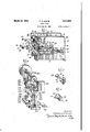
PUNCH PRESS Filed May 12, 1941 4 Sheets-Sheet 2 I 156 HIM..
322 177 we; R154 w 142 H \VENTOR.
March 30, 1943.
F. H. LESLIE 2,314,886
PUNCH PRESS Filed May 12,- 1941 4 Sheets-Sheet 3 INVENTOR.
F. H. LESLIE 2,314,886
PUNCH PRESS I Filed May 12, 1941 4 Sheets-Sheet 4 1% l: l 303 I I J v /60 I 942 BY .L A. 6. PL?
INVENTOR.
Patented Mar. 30, 1943 UNITED STAT 11 Claims."
This invention relates to improvements in punch presses and has to do with improvements particularly applicable to that type of press disclosed in applicants co-pending application, Serial No. 276,247, filed May 27, 1939.
The punch press illustrated and described in applicants co-pending application developed from a subpress composed of two substantially parallel, elongated, metallic leaves spaced from each other and held in assembled relationship by means positioned at one end of the assembly only, see Figures 4 and 6 of the co-pending application. The mounting of this subpress as a permanent fixture in a punch press is illustrated in Figure 1 in the co-pending application and indicates that the length of the leaves of the subpress is determined solely by the necessity of having a pivotal point at a substantial distance from the punching zone, and as a result, the pivotal point of the upper leaf is mounted on an extension of the framework behind the main portion of the punch press, and bears no relation ship to the throat of the press.
Since the designing of the machine shown in the co-pending application, the possibility of combining the elongated leaf with the throat of the press to provide a deep throat press has been conceived. Enlarging on this, and referring to Figure 1 of the co-pending application, it will be noted that the punch press consists of a subpress mounted between means for causing the free ends of theleaves (or the free end of a single leaf) to move with respect to each other. No relationship between the throat of the press and the pivotal point of the leaf is shown. On the other hand, the accuracy obtainable by means of the long substantially inflexible leaf acting in the punching zone is in no way. assisted by the shallow throat construction of the punch press.
In the art, accuracy in so-oalled deep throated presses is exceedingly difficult to obtain. In such presses, it is essential that leader-pin die sets be used and a leader-pin die set permitting a clearance from the front of the press of twelve inches may weigh as much as 200 pounds. Such a load must be raised and lowered by the driving mechanism and this reciprocation of a heavy weight is partly responsible for high wear occurring in these types of machine. Moreover, a leader-pin die set is subject to forces tending to misalign punch and die. In leader pin die sets where all of the dowels are mounted at the rear of the punch holder, the positioning of punches toward the forward part of such a leader-pin die set will tend during a punching operation to spread the has a six-inch throat.
punch holder and the die shoe and cause improper registry of the punch and die.
The first object of this invention is to relate the throat of a press to the pivotal point of a punch plate holder leaf of the type shown in the co-pending application so that the depth to which a workpiece may be inserted through the punching zone into the throat will be at least as great as the distance behind the punching zone of the pivotal point of the punch plate holder leaf. Speaking in terms of actual dimensions, the punch press shown in the co-pending application The distance from the front of the punch holder leaf to the pivotal point is some fourteen inches. One of the features of the present invention is, the cutting back of the throat of the punch press frame to a point behind this pivotal point and of properly reinforcing the frame so that the punching operation may nevertheless be performed without great deformation of the frame. It will be appreciated that this and may be accomplished either by permanently fastening the punch plate holder leaf to the frame of the press or by providing a deep throated press in conjunction with a separate subpress of the type illustrated in Figures 4, 5 and 6 of the co-pending application.
In connection with relating the throat depth to the pivotal point of the leaf carrying the punch plate holder it is important that the fundamental difference between applicants type of press and conventional punch presses be noted. In the con ventional type of press, the die shoe is supported on the lower jaw of the throat while the punch plate is suported on the upper jaw of the throat. When a punch enters a workpiece the resistance tends to spread the jaws of the throat and in so doing misaligns the punch and the die. It is for this reason that the throat on conventional punch presses is very heavy and comparatively shallow because the greater the depth of the throat the greater amount of metal necessary for holding the longer upper jaw in a fixed relationship to the lower jaw. In applicants type of punch press on the other hand, the punch plate and the die shoe are both mounted on the lower jaw while only the means for applying power for moving the punch plate holder leaf with respect to the die shoe is mounted on the upper jaw, there being provided means for varying the application of force to the punch plate holder leaf when the jaws of the throat spread due to the impact of the punch upon the workpiece. In applicants type of punch press, in order to assure alignment of the punch and the die, all that is necessary is a base of sufficient strength not to be deformed by any expansion of the upper leaf due to the presence of a resisting force to the entering of the punch into the workpiece. In short, the resistance to deformation of the upper jaw of applicants punch press need only be sufficiently great to cause the punch to enter the die. Inasmuch as a punch ordinarily enters a die by a distance of t; to -6 of an inch, the upper jaw of the throat of applicants press may be deformed by a substantial amount without in any way impairing the functioning of the press or the entry of the punch into the die.
The second object of this invention is to provide a new and improved substantially inflexible leaf for holding the punch plate holder. As disclosed in the co-pending application, the substantially inflexible leaf has a weakened portion adjacent to the point where it is affixed to the frame of the punch press. So long as the press was manually operated, no adverse effects of flexing at the weakened portion were noted. After power was applied'tothe press (several power embodiments are shown in this applica tion) the leaf was flexed so frequently at its pivotal point'that the metal apparently crystallized or fatigued in some way so that the life of a leaf was shorter than desired. One of the features of this invention is the provision of a piece of flexible material such as spring steel at that point where the substantially inflexible leaf is to be permitted to bend with reference to the punch plate bed. In the actual construction, the substantially inflexible leaf which holds the punch plate holder is no longer afiixed to the frame of the punch press but to a spring steel strip which is affixed to the frame. By this arrangement the leaf may be of as hard material as desired without any bad eflects due to flexing of the metal, because there is no flexing, while the point of flexing may be made of a material which may be flexed without altering its structure.
7 The third object of this invention is to provide means 'for eliminating the necessity of raising the punch plate holder a great distance from the punch bed in order to mount in the punch plate holder a conventional type of punch plate. The ordinary punch plate includes a large cylindrical lug, usually formed integrally with the punch plate and extending above the punch plate for a distance of two inches or thereabouts. If the punch plate is in association with a die shoe, all forming part of a leader-pin die set, a considerable distance between the die bed of the punch press and'the punch plate holder is necessary in order to insert the assembly for operation. In conventional punch presses having rams and slides, there is usually an adjustment which makes it possible to raise the punch plate holder for a considerable distance. In applicants type of punch press where a substantially inflexible elongated leaf is used for obtaining registry between the punch and the die, the leaf permits a comparatively short stroke. Consequently, it is not possible to raise the end of the leaf (which either is orsupports the punch plate holder) as high as may be desired in order to mount the punch plate.
- One "of the features of this invention is the provision of a slot in the forward side of the punch plate holder (it is immaterial whether the punch plate holder is the end of the leaf itself or a separate member) which slot extends into the punch plate holder to the center of the punching zone. The upward extending lug on the conventional punch plate may be inserted horizontally into the slot and then a capping plate is used for holding it in position.
Another object of this invention is to prevent lateral movement of the end of the leaf carrying the punch plate holder or which itself constitutes the punch plate holder. While off center loading has not been found to misalign the punch and the die due to lateral movements of the leaf, the strength of the leaf together with the weakened portion where it flexes being sufficient, it is possible to position a punch having a cutting edge well below the capacity of the press at one side of the punch plate for the purpose of making a cut in one side of a sheet at its edge. This type of out has a strong lateral displacing effect upon the leaf, and in order to counteract this, one of the features of applicants invention is the provision of two set screws engaging the opposite side edges of the leaf at the leafs front, whereby the set screws act as ways while the leaf itself acts as a slide, it being remembered that the stroke of applicants press is comparatively short. In the preferred form, the'set screws engage the punch plate itself and not the punch plate holder.
Another object of this invention is to provide means for adjusting the distance between the punch plate holder and the bed of the punch plate in order to accommodate punches of varying lengths. fhe problem here sought to be cured arises from the fact that the vertical dimensions of punches may vary due to their other dimensions. These differences in vertical heights of punches could be compensated for by shims or insert plates positioned between the punch plate and the punch plate holder but in many presses it is common to provide means for altering the height of the punch plate holder to suit various punches without the use of such insert plates. Applicant provides a plurality of means for adjusting the height of the punch plate holder with respect to the bed of the punch press. These means have the merit of not interfering with the principle that the broad rotatable cam should turn freely on a shaft to which it is not keyed, thereby eliminating wear at journals in the frame of the punch press.
A further oject of this invention is to provide improved means for holding the leaf carrying the punch plate holder in engagement with whatever driving force is utilized. In the punch press shown in the co-pending application, the leaf is held in engagement with the cam by means of the springs I62 and I86 in Figure 1. In a power application these springs create considerable back lash in the leaf. One of the features of the present invention is the provision of means for causing the free end of the leaf to move upwardly positively with the driving force just as it moves downwardly positively with the driving force. By this arrangement, the leaf is caused to move upwardly in the same controlled way that it moves downwardly. Back lash is greatly reduced.
Another object of this invention is to reduce horizontal thrust between the leaf supporting the punch plate holder and the driving means. Applicant has encountered a difiicult problem in applying the force of the broad cam to the end of the leaf in that the cam, by exerting a rearward thrust between its own surface at the point Where it engages the leaf and the leaf itself, tends during a punching operation to spread the frame of the punch press not only as between the jaws of the punch press but as between the upper jaw supporting the cam and the point on the frame to which the leaf is fastened. One of the features of the present invention which is carried out in several of the embodiments is the spacing of the cam at a point sufficiently far above the leaf to permit the insertion of a substantially vertically moving driving member having a knife edge in engagement with the top of the leaf. Experiment indicates that rearward thrust between the cam and the leaf is reduced.
Another object of this invention is to apply power to such punch presses. One of the features of this invention is the positioning of a pinion gear on the driving cam in such a fashion that the gear may be driven by a second pinion, thereby not driving through journals in the frame. As will be seen in the description hereafter, the driving pinion is mounted in a shaft which is journalled in a frame, but the relationship of the driving pinion to the driven pinion is not one Which is affected by the blow exerted on the cam and the cam bearing surface when the punch enters the workpiece. The journals in the shaft carrying the pinion do nothing more than support the pinion against whatever resisting torque is presented by the driven pinion.
In presenting power presses, another object of the applicant was to remove the fly wheel from the front of the punch press. In most punch presses the fly wheel is high and forward and would be interfering with the operator. In certain of the constructions shown in the accompanying drawings, the fly wheel has been moved to the rear of the press.
Another object of this invention is to provide new and improved means for moving the leaf carrying the punch plate holder relative to the punch press bed. More particularly, the embodiment of a leaf makes it possible to employ a rocker arm drive construction whereby it is possible to mount the motor and fly wheel to the rear of the punch press in space ordinarily not utilized.
Another object of this invention is to provide a new and novel stripper for removing the workpiece from the tool or punch. The construction of many conventional punch presses includes heavy blocks at the base of the ram which necessitate the employment of complicated strippers. These heavy blocks of material are in part due to the need of sufficient strength to handle heavy leader-pin die sets. One of the features of this invention is the provision of vertically slidable stripper pin mounted in the punch plate holder itself and extending downwardly toward the punch plate. The height of the bottom of these stripper pins with respect to the die in a die shoe may be adjusted and they will move upwardly and downwardly with the punch plate and punch plate holder excepting that at a predetermined point in the upward movement they will be blocked so that the punches will continue to rise with respect to the stripper pins. Any workpiece adhering to the punch or punches will of necessity be removed therefrom.
These and such other objects as may hereinafter appear are attained in the several embodiments of the invention shown in the accompanying drawings, comprising four sheets, wherein:
Figure 1 is a perspective view in exploded form of one form of punch press;
Figure 2 is a view of the means for adjusting the height of the leaf with respect to the bed;
Figure 3 is a view of the driving cam; Figure 4 is a perspective view of a power application to applicants type of punch press;
Figure 5 is a perspective view of another means of applying power to applicants punch press;
Figure 6 is a perspective View of one form of power driven punch press;
Figure 7 is a front elevational view of one form of power driven punch press;
Figure 8 is a perspective view of still another power application to applicants punch press;
Figures 9 and 10 are front and side elevational views respectively of one means of adjusting the height of the punch plate holder with respect to the punch plate bed;
Figure 11 is a perspective view partly cut away of another means of adjusting the height of the punch plate holder with respect to the punch plate bed; and j Figure 12 is another perspective view of anotherpower application of applicants punch.
Continuing to refer to the drawings and particularly to Figure 1, the broad object of this invention is obtained by a punch press generally identified by the numeral l0 comprising two complementary wall members I2 and M maintained in vertical spaced relationship by an upper support a die shoe bed It and a leaf supporting member 26. While these parts are assembled from fabricated steel plates by means of welding, it is evident that a cast jaw would be equally satisfactory from a performance standpoint. The two complementary wall members i2 and M are cut back from the front side of the press to form an upper jaw 22 and a lower jaw 24. The depth of the jaw as defined by the walls 26 and 28 is determined by the forward limit of a flexible projecting member 30. This flexible projecting member 30 is mounted; preferably removably, but rigidly, on the member 20 and is at the horizontal level which is normally occupied by the top of'a die mounted on a die shoe (neither of which are shown) on the die shoe bed !8. The flexible projecting member 30 is formed of spring steel which may be flexed without altering its grain structure. The forwardly protruding edge of the flexible projecting member 30 supports a leaf 32by means of an offset portion 34 which raises the horizontal portion of the leaf 32 to any desired height. A punch plate holder 36 is mounted by anysuitable means upon the forward end of the leaf 7 32. As shown in Figure l, the punch plate holder 36 is formed from a separate piece of metal fastened by Welding or other suitable means to the leaf 32. This relationship, however, is purely one of manufacturing convenience for in other. presses, such as those shown in Figures 8 and 9, the leaf is not cut short as shown in Figure 1 but extends into the punching zone 3'! so that the forward end of the leaf itself acts as the punch plate holder.
Summarizing the press as disclosed at this point, itwill be noted that the punch plate holder 36 through the leaf 32 and flexible projecting member 36 is supported on the portion of the complementary wall members I 2 and l4 forming the lower jaw 24. Assuming the mounting of a punch plate and punch beneath the punch plate holder 35 and of a die and die shoe on the die shoe bed l8, the level at which the.
punch enters the die will be approximately the level of the flexible projecting member 39. In order to alter the relationship of the punch to the die either the leaf 32 must be deformed from normal or the lower jaw 24 must be deformed from normal or the mounting means, generally identified by the numeral 38, must permit an altered relationship between the leaf 32 and the lower jaw 24. Because these parts are made of heavy steel and because the flexible projecting member 30 is very short, it would be necessary for some force to be present to cause such a deformation. No such force is present. No matter how power is applied to the punch plate holder 36 (that is, the forward end of the leaf 32) as the punch enters the die the opposing force will be taken up by the upper jaw 22 which may be spread so as to require a longer stroke of whatever force is used for moving the leaf 32 downwardly than would be necessary if the upper jaw 22 was not spread, but this spreading action can only be communicated to the punch plate holder 35 by deformation of the vertical wall portion indicated by the numeral 4!] acting upon the supporting member 29. This deformation is practically negligible. It is evident, therefore, that misalignment of the punch plate holder 35 together with whatever is mounted therebelow with the die shoe bed it together with whatever is mounted thereon can only occur if the lower jaw 24 and the member 20 are deformed.
Continuing to refer to Figure 1, the punch plate holder end of the leaf 32 is moved rela tively to the die shoe bed I8 by means of a cam 42 mounted on a shaft 44 which in turn is mounted oif center on two bearing members 46 and 48 which in turn are disposed in journals 50 and 52 in the complementary vertical walls I2 and I4. Centrally of the cam 42 is a handle 54 and on both sides thereof are ring elements 56 and 58 formed integrally in the particular embodiment shown with a driving link 60. This driving link has a knife or rounded edge 62 which engages a groove 54 in the top of the punch plate holder 36. By this arrangement, movement of the handle 54 will raise or lower the link 66. The capacity of the punch press will depend upon the bearing area between the broad cam 42 and the shaft 44 upon which it is mounted and the bearing area between the ring members 56 and 58 and the external surface of the broad cam 42 which they engage. While the ring members 55 and 58 are shown comparatively narrow, it will be appreciated that they may be broadened inwardly toward the handle 54 to' greatly increase the bearing surface area between themselves and the broad cam 42. It will be understood that operation of this driving assembly develops no frictional wear in the journals and 52 because the bearings 46 and 48 are not turned when the handle 54 is moved because the broad cam 42 turns freely upon the shaft 44. Referring to Figure 3, it will be noted that the hole 66 through the broad cam 42 is directly above the axis 68 of the broad cam when the handle 54 is in the position shown. When the handle is moved into the dotted position indicated by the numeral H1 in Figure 1, the broad cam 42 will be near its uppermost position. Inasmuch as thehandle 54 can be moved approximately 180 degrees, it follows that the stroke of the link 69 is approximately twice the distance from the center of the hole 66, see Figure 3, to the axis 58 of the broad cam 42. It will be noted in this arrangement that the driving cam 42 is positioned at a point substantially above the punch plate holder 35 and that the link 60 applies other than exactly vertical pressure upon the punch plate holder 38 only at those times when the link is not acting at exactly right angles to the punch plate holder 36. The deflection of the link 69 from the vertical at any time is comparatively small, so small that thrust rearwardly upon the leaf 32 is negligible. Moreover, spreading of the upper jaw 22 with respect to the lower jaw 24 has no effect upon deforming the leaf 32 excepting insofar as it may slightly alter the position of the link 60 with respect to the vertical.
By the action thus described, it is apparent that the resistance of the workpiece to the punch or punches has no appreciable effect upon the relationship of the punch and the die because the resistance is expended in deforming the upper jaw 22 of the punch press to which the leaf 32 is not fastened.
; One of the features of the punch press shown is the slot 12 extending from the front of the punch plate holder 36 to the vertical axis 14 of the punching zone 31. 6 identifies a conventional punch plate with an upwardly extending cylindrical lug 13. It is evident that instead of having to raise the leaf 32 in order to insert the lug 18 in a hole in the punch plate holder 36, all that is necessary is to advance the lug 18 through the slot 12 into position. A cut-out portion in the link provides head clearance for lugs of various heights. The punch plate holder is held in position by a capping member 82 held in position by screws 84 and 85 in holes 88 and 90 the forward edge of the punch plate holder Another feature of this invention is the elimination of a spring relationship between the leaf 32 and the upper jaw 22. Referring for the moment to Figure 8, it will be noted that two springs 92 and 94 are utilized as the means for holding the leaf carrying the punch plate against the driving force. As mentioned heretofore, this arrangement develops considerable back lash and slapping between the upper edge of the leaf and whatever driving means is used. embodiment shown in Figure 1, the driving link 60 has outwardly extending portions 96 and 98 over the ends of which are positioned brackets H30 and I02 welded or otherwise suitably fastened to the punch plate'holder 32. Screws I04 and I06 provide the means'for holding the outwardly extending portions 95 and 98 in tight relationship with the punch plate holder 36. It will be understood, of course, that the screws H14 and H36 have rounded tips so as to permit a sliding action between the outwardly extending portions 96 and 98 and the driving link 58 due to any deformation of the upper jaw 22 during the punching process.
Another feature of this embodiment of the invention resides in the means of raising or lowering the punch plate holder 36 with respect to the die shoe bed It. Punches are of various lengths due to a variety of factors not pertinent here. It is desirable that the distance from the cutting edge of the punch to the die be approximately the same regardless of the length of the punch and consequently there is provided a means for raising or lowering the shaft 44, see Figure 2, with respect to the punch press. This means consists of the two bearing members 46 and 45 in which the shaft 44 is mounted eccentrically. These bearing members 45 and 48 are keyed to the shaft In the 'of the press is clear.
44 by two pins IE8 and I I8. Disposed in the face of the bearing member E8 at a point outside the complementary vertical wall I4, see Figure 1, is a sector segment I I2 having near its circumference a plurality of holes H4, H6 and th like. The sector segment I I2 is rigidly mounted in the bearing member 48 and it is evident that by rotating the bearing member 48, the bearing member 36 will likewise rotate and the shaft 24, being eccentrically mounted with respect to these two bearing members, will be raised or lowered with respect to the punch press as a whole. A set screw I I8 through the uppermost hole of the sector segment II2 may be seated in a hole, not shown, in the complementary vertical wall I I. By removing the set screw H3 and causing any one of the other holes, such as 5, to come into registry with the hole in the complementary vertical wall It, the bearings 46 and 48 may be turned and locked in any position. By this simple arrangement, the initial uppermost position of the punch plate holder 35 may be raised or lowered.
Figure 4 presents a preferred form of power application. In this arrangement, the upper jaw of the punch press is greatly shortened, being generally identified by the numeral I20 and ter- 'minating at the point I22 which is well behind the punching zone of the press. Mounted in a journal I24 in the jaw I20 is a shaft I26 which supports a rocker arm, generally identified by the numeral I28, and consisting of two complementary members I39 and I32 held in assembled relationship by spacer members, one of which is shown, I34. On the forward side of the rocker arm I28 is a driving link or plate I35 mounted on the ends of the two complementary members I30 and I32 by cap screws I38. It will be observed that the plate I35 has two vertical slots I40 and I42 through which the cap screws, such as I38, pass. The purpose of the slot is to provide that adjustability of height of the punch plate holder I44 which was obtained in the first embodiment of the invention by the journal members 86 and 18, see Figure 2. The driving plate I36 follows the rocker arm I23 upwardly because the cap screw I46 is threaded through a cross-piece I48 into the top of the driving plate I35. The blow from the punch entering the workpiece is taken up by the set screws I50 and I52 which threadedly engage the forward ends of the complementary members I38 and I32 and rest on the upper surface I54 of the driving plate I36. The punch plate holder I44 is held in assembled relationship to the driving plate I36 in a manner similar to that described heretofore for holding the driving link GEI, in Figure 1, to the punch plate holder 36. In the upper rear of the rocker arm I28 is journalled a shaft I55 which through a link I58 operating on a cam I59 disposed on a shaft I62 will cause the rocker arm I28 to rock when the shaft I62 is rotated as by power derived from a line shaft.
The principal merit of this driving arrangement lies in the fact that the bearing I28 supporting the rocker arm may be positioned fairly close to the vertically extending wall I64 :With the rocker arm taking up considerable of the deformation pressure derived from the punch entering the workpiece. Moreover, the fly wheel may be mounted at the rear of the punch press as shown by the fly wheel I66. The great advantage of this press lies in the fact that the whole front The press may be positioned between work tables on either side thereof and strips of metal may be advanced from one side through to the other with the punching area well in front of the insideedge of the workpiece.
The embodiment of the invention shown in Figure 4 also shows a novel stripper. The stripper consists of four pins, three of which, I68, I79 and I12, may be seen as positioned in holes in the punch plate holder I44. Suspended from the lower ends of the four pins, such as I68, I'IIi and H2, is a stripper plate I69. Each of the four stripper pins has a horizontal pin such as III positioned at right angles to its length for the purpose of preventing the stripper pins from dropping lower than a predetermined point with reference to the punch plate holder I4 4. Projecting forwardly of the upper jaw members are two arms I13 and III, the arm I73 being positioned to engage the stripper pin I68 and its complementary member, not shown, while the arm I l I is positioned to engage the tops of the pins III] and I72. It will be appreciated that the arms I13 and III engage th tops of the stripper pins at a point prior to the maximum rise of the punch plate holder WI and that as a result of this arrangement, a piece of metal being held to the punch, indicated by the numeral I153, will be carried upwardly with the stripper plate I89 until upward movement of the stripper plate is prevented by the upper ends of the stripper pins engaging the arms I73 and III, at which time the punch I19 will continue its upper movement but the stripper plate I69 will strip the workpiece from the punch I19.
The means for holding the punch plate holder in assembled relationship with the rocker arm driving assembly is similar to the structure heretofore shown in Figure 1, and will not again be described.
In Figures 9 and 10 there is shown another arrangement for raising and lowering the punch plate holder while Figure 11 shows a third .arrangement for doing the same thing, which arrangement is a preferred form in hand presses. Referring to Figures 9 and 10, the form is very similar to that described in Figure 1. I80 and I82 d are the complementary Walls forming the upper jaw of a punch press. In journals I84 and I36 are positioned two bearing members I88 and I90 in which eccentrically is positioned a shaft I92, which shaft is keyed to the bearing, members I88 and I90 by the keys I94 and I96. C'oncentrically with the shaft I92 and keyed through by the same keys I94 and I96 are two adjustable disks I98 and we having circumferential scallops 2B2 therein. The circumferential scallops 202 may be caused to register with a hole, as 204, in the complementary wall members as I82, see Figure 10, so that a set screw 266 may hold the horizontal shaft I92 at any desired level by seating the set screw through any selected notch in a hole, as 2B4, in the wall I82. In Figures 9 and 10, guide pins for engaging the sides of the punch plate holder or of the leaf supporting the punch plate holder are shown. Referring to- Figure 9, by means of two set screws 2 m and. 2 I2 mounted in the complementary walls I86 and I82 and projecting therethrough to engage the sides of a-punch plate holder 2H3, 2I6 being the supporting leaf, lateral positioning of the punch plate is assisted. The tips 2I8 and 226 of the set screws 2) and 2 I 2 are hardened so as to resist wear and it has been practice to dispose hardened steel inserts in the punch'plate holder at the points Where the set screws 2H) and 2 I2 engage the punch plate holder in order to resist wear on the punch plate holder. Ihis set screw arrangement constitutes a very simple slide and way construction. While the lateral strength of the leaf is generally sufficient to prevent offsetting of the punch with respect to the die so that under most conditions the set screws 2 l 8 and 2|2 are unnecessary, certain unusual punching operations are materially assisted by the employment of said set screws.
Referring to Figure 11, an alternative means of initially positioning the height of the leaf is provided. This arrangement is shown in use in the embodiment of the invention shown in Figure 8. In this arrangement the complementary supporting walls, shown partly cut away, are similar to those described for other embodiments of the machine. The unique feature of the invention resides in the shaft 238 wherein the bearing 232 is on the same axis as the bearing 234 while the long bearing 236 upon which the cam 238 is freely rotatable is mounted eccentrioally to the bearings 232 and 234. By rotating the shaft 238, it is evident that the'bearing member 236 may be raised or lowered with respect to the punch press as a whole.
For the purpose of holding the bearing member 236 at any particular point, a clamp member 248, see Figure 8, pivoted at 242 on the upper jaw of thepunch press has a journal 244 for receiving the bearing 234 of the shaft 238. The free end of the clamping member 248 is split so as to provide sufficient resiliency for a screw 246 to draw up the two portions formin the journal 238 tightly on the bearing member 234. This embodiment of the means for initially positioning the height of the driving member or cam, such as 236, is superior to the forms shown in Figures 9 and 10 and Figure 1, in that the initial position may be varied gradually and need not be changed by steps of a definite size.
The remaining figures are devoted to means of communicating power to a punch press of the type described by the applicant. In Figure 5, the punch plate holder 258 and supporting leaf 252 together with a vertically disposed driving link or ram 254 are of the type disclosed in the embodiment shown in Figure 1. The means for communicating a reciprocating or up and down movement of the punch plate holder 258 consists of a shaft 256 supported in the complementary walls 258 and 268 forming the upper jaw of the punch press. A long bearing 262 isv mounted eccentrically with respect to the shaft 256 as in other embodiments of the invention. Centrally disposed on, the long bearing 262 and at approximately the midpoint between the complementary walls 253 and 268 is a pinion gear 264 rotatable on the same axis as the shaft 256 which may be attained by providing a ring member 266 at the midpoint of the long bearing 262, which ring member is concentric with the shaft 256 and to which is keyed a pinion gear by the key 268.
Continuing the description of the power embodiment shown in Figure 5, a driving member 268 having upwardly projecting arms 218 and 212 is disposed beneath the shaft 256, the arms 218 and 212 having journals for mounting on the cam or bearing, such as 262, one being on each side of the pinion gear 264. The relationship of the driving member 268 and the link 254 is constant during operation, although adjustment may be made by means of two set screws 214 and 216, the positioning of the two supporting screws 2'18 and 288 being compensated for. The set screws 214 and 276 hold the driving member 268 tightly to the link 254 so that on the upper stroke back lash of the punch plate holder 258 and the leaf 252 is minimized. During the downward stroke, the blow when the punch enters the workpiece is absorbed by the supporting screws 218 and 288 which are. threaded into the driving member 268 and have heads permitting them to be drawn tightly against the link 254.
It will be noted that a heavy plate 282 fastened by any suitable means to the rear bottom of the driven link 254 depends downwardly so as to be in surface engagement with the link 254. The link 254 is slotted at 284 and 236 and set screws 288 and 298 mounted in the depending plate 282 are positioned in the slides. If it is desired to raise or lower the punch plate holder, the supporting screws 218 and 288 will be loosened as will the cap screws 288 and 298. The cap screws 214 and 276 will then be turned to obtain any desired height of the punch plate holder 258. The set screws 213 and 288 will then be screwed down until their heads firmly engage the link 254. When this occurs the cap screws 288 and 238 will be turned down tight.
In Figures 6 and '7, there is shown a further means of applying power to the punch press disclosed in the co-pending application. Referring to Figure 6, the simplest form of this invention, namely, a leaf and broad cam, is retained, there being a shaft 298 disposed in the upper jaw of the punch press with a fly wheel 292 disposed on one end thereof. A motor 296 mounted on a platform 294 forming part of the frame of the punch press drives by means of the belt 296 and the fly wheel 292. It will be understood that by this arrangement the power is applied through the shaft 298 and that as a consequence thereof the journals in the upper jaw of the punch press in which the shaft 298 is mounted is subjected to heavy wear. In order to convert the rotating movement of the shaft 296 to a reciprocating or up and down movement for the punch plate, a driving member 388 having a long journal for engaging the entire outer surface for a cam 382 is provided. Depending from the driving member 388 is a portion 384 from which is adjustably suspended a driving bar 356 which is wedge shaped and makes approximately a line contact with a groove 388 in a plate 318 mounted on the reciprocabl'e leaf 3!! of the punch press. It is evident that by means of this line contact changing angularity of the driving bar 386 with respect to the leaf will be immaterial.
In order to adjust the height of the punch plate holder and leaf 3l1 with respect to the die shoe in order to compensate for punches of varying heights, the driving bar 386 is held' to the driving member 388 by two screw threaded members 3l2 and 3M. The ends of these members 3l2 and.3|4 are reversely threaded and it is apparent that by turning them the driving bar 386 may be drawn toward or separated from the driving member 388. Suitable means, such as nuts, are provided for locking the screw members 312 and 3M in any desired position. In order to lift the leaf 3!! on an upstroke of the driving member 388, a bolt 3| 6 having a head 3i9, see Figure 7, seated in a lower recess 32l in the plate 3l'8 has its shank 323 disposed in a hole through the driving bar 386, which hole has a diameter considerably in excess of the diameter of the bolt 3H6. A spring 325 and nut 321 holds the bolt 3l6 in assembled relationship with the driving bar 386 and the plate 318. Inasmuch the leaf 3, it is evident that on an upstroke of the driving bar litfithe plate 3H] and the leaf 3|! will be lifted. V
The stripper shown in Figure 6 is similar to the type described in the invention shown in Figure 4, it being noted that in this embodiment of the invention the means for preventing the stripper pins from rising above a certain point are brackets, such as SIB and 329, shown in Figure 7, having set screws, such as 322 and 324 adapted to engage the pins holding the stripper.
In Figure 8 is another embodiment of a power application which closely adheres to the punch press design as disclosed in the co-pending application. In this embodiment, the press is sub-' stantially unaltered, although a handle on the driving cam 338 is replaced by a U-shaped bracket 332 which through a link 334 and a crank shaft 333 is reciprocated by means of a rotating shaft 333 deriving power through a belt 346 from a source of power as the motor '342. In this arrangement, the shaft 230 is not rotated, the broad cam 53% being free to rotate upon the shaft. The advantages of small wear due to a broad bearing surface directly above the punching zone is, therefore, retained in this power application.
Another embodiment showing means for applying power to this invention is shown in Figure 12. In this embodiment power is derived from a shaft 344 carrying a fly wheel 3&5 and being driven by any suitable means. Mounted eccentrically on the shaft 3% is a cam 3:33 which through a coupling 359 creates a reciprocating movement in the link 352. The link 352 is coupled at its forward end to a toggle assembly generally identified by the numeral 354 which comprises a lower member 356 pivoted at opposite ends to a punch plate 358 at points such as 359 and an upper member 362 pivoted in brackets 35:? and 3655, joined to each other by any suitable means and mounted on the upper jaw of the punch press. The upper members 352 and the lower members 356 of the toggle assembly 354 are held pivotal assembly by a shaft 368 which also carries a member 3') afiixed to the link 3552. It is apparent that by reciprocating the link 352 horizontally, the punch plate 358 will be raised and lowered. In order to provide adjustment in height for the punch plate at the beginning of its stroke, the brackets 364 and 366 are adjustably held to the upper jaws by means of cap screws, such as 3T2, disposed in slots such as 374. Cap screws 3H disposed on the upper jaw of the punch press threadedly engage the brackets 36 and 35% whereby when the cap screws, such as 3l2, have been loosened together with the two set screws 3'68 and 380, the brackets 364 and 366 may be raised or lowered with respect to the upper jaw of the press and thereby raise or lower the normal height of the punch plate holder 358 with respect to the press.
Having thus described my invention, what I claim as new and desire to secure by Letters Pat ent of the United States is: 1. A punch press comprising a base, a punching zone above one portion of said base, a flexible leaf having one end aflixed to another portion of said base and having its free end extending into the punching zone, Vertical support means mounted on the base adjacent to that portion to which the leaf is afiixed, and means on said support means for moving the free end of the leaf in the punching zone, whereby the distance from the punching zone to the vertical supports may define the depth towhich a workpiece may sorted through the punching zone.
2. A punch press comprising a base, a punching zone above one portion of said base, an elongated leaf offset so as to have an upper end portion and a lower end portion, means for pivotally mounting the lower end portion on said base so that the upper end portion extends into the punching zone, and means for moving the free end of the leaf supported on the base at a point approximately in alignment with the punching zone and the means for pivotally mounting the elongated leaf and at a distance greater than the distance from the punching zone to the offset portion of the leaf whereby the distance from the punching zone to the offset portion of the leaf defines the depth to which a workpiece may be inserted through the punching zone.
3. A punch press comprising a vertically disposed member joining upper and lower jawmemhere to form a throat, a punching zone in the throat, an elongated leaf having one end mounted on the vertically disposed member and its free end extending into the punching zone, whereby the distance from the punching zone to the vertically disposed member defines the depth to which a workpiece may be inserted through the punching zone, and means mounted on the upper jaw member for moving the free end of the leaf in the punching zone.
4. A punch press comprising a base having a punching zone above one portion thereof, an elongated flexible leaf mounted at one end tosaid base and having its free end in said punching zone, and means for moving the free end of said leaf in the punching zone, said latter named means being mounted on said base at a point adjacent to the point where the leaf is affixed to the base, whereby the distance from the punching zone to the point where the means for movin the free end of the leaf is mounted on the base may define the depth to which a workpiece may be inserted through the punching zone.
5. A punch press comprising a base, a punching zone above a portion of said base, an offset leaf portion pivotally mounted on said base at approximately the level of the top of a die positioned in the punching zone, the free end of said offset leaf extending into the punching zone, and means for moving the free end of said offset leaf in the punching zone, said latter named means being mounted on the base adjacent the pivotal mounting of the leaf on the base, whereby the distance from the punching zone to the point where the means for moving the free end of the leaf is mounted on the base may define the depth to which a workpiece may b inserted through the punching zone.
6. A punch press comprising a base, a punching zone above a portion of said base, a flexible leaf mounted at one end of said base outside the punching zone so as to permit vertical flexing of the free end, a substantially rigid leaf mounted at one end on the free end of the flexible leaf and having its free end extending into the punching zone, and means for causing the free end of the substantially inflexible leaf to move in the punching zone, said latter named means being mounted on a support fastened to the base adjacent the flexible leaf, whereby the distance from the punching zone approximately to the flexible leaf defines the depth to which a workpiece may be inserted through the punching zone.
'7. A punch press comprising a base, a punching zone above a portion of said base, a flexible leaf be. in V mounted at one end of said base outside the punching zone so as to permit vertical flexing of the free end, that portion of said leaf which flexes being in approximately the same plane as the top of a die mounted in the punching zone, a substantially rigid leaf mounted at one end on the free end of the flexible leaf and having its free end extending into the punching zone,
and means for causing the free end of the substantially inflexible leaf to move in the punch ing zone, said latter named means being mounted on a support fastened to the base adjacent the flexible leaf, whereby the distance from the punching zone to the point where the means for moving the free end of the leaf is mounted on the base may define the depth to which a workpiece may be inserted through the punching zone.
8. A punch press comprising a base, a bolster plate mounted on said base for holding a die, a substantially inflexible leaf having a free end above said bolster plate and fastened at its other end to said base, said substantially inflexible leaf having a weakened portion across a portion of its length whereby to permit vertical movement of the free end of the leaf about said Weak ened portion as a pivot, means for moving the free end of said leaf in the punching zone supported on the base adjacent to the pivot point of the leaf, and means for varying the direction of pressure on the free end of the leaf, whereby misalignment of the pressure applying means with respect to the base will not misalign the free end of the leaf.
9. A punch press comprising a base, a bolster plate mounted on said base for holding a die, a substantially inflexible leaf having a free end above said bolster plate and fastened at its other end to said base, said substantially inflexible leaf having a weakened portion acrossa portion of its length whereby to permit vertical movement of the free end of the leaf about said weakened portion as a pivot, means for moving the free end of said leaf in the punching zone supported on the base adjacent to the pivot point of the leaf, and means for varying the direction of pressure on the free end of the leaf, whereby misalignment of the pressure applying means with re spect to the base will not misalign. the free end of the leaf, said latter named means comprising a cam, a link driven by said cam and engaging the top of the free end of the leaf.
10. A punch press comprising a base, a bolster plate mounted on said base for holding a die, a substantially inflexible leaf having a free end above said bolster plate and fastened at its other end to said base, said substantially inflexible leaf having. a weakened portion across a portion of its length whereby to permit vertical movement of the free end of the leaf about said weakened portion as a pivot, means for moving the free end of said leaf in the punching zone supported on the base adjacent to the pivot point of the leaf, and means for varying the direction of pressure on the free end of the leaf, whereby mis alignment of the pressure applying means with respect to the base will not misalign the free end of the leaf, said latter named means comprising a cam, a link positioned for vertical reciprocating movement by said cam, and means on the free end of the leaf for permitting the link to move the leaf regardless of the angle of the link with respect to the leaf.
11. A punch press comprising a base, a bolster plate mounted on said base for holding a die,,a substantially inflexible leaf having a free end above said bolster plate and fastened at its other end to said base, said substantially inflexible leaf having a weakened portion across a portion of its length whereby to permit vertical movement of the free end of the leaf about said weakened portion as a pivot, means for moving the free end of said leaf in the punching zone supported on the base adjacent to the pivot point of the leaf, and means for varying the direction of pressure on the free end of the leaf, whereby misalignment of the pressure applying means with respect to the base will not misalign the free end of the leaf, said latter named means comprising a cam, a link positioned for vertical reciprocating movement by said cam and having a depending driving edge transverse to the length of the substantially inflexible leaf, a transverse groove in the free end of the leaf in which the driving edge of the link is seated, and means for holding the link and the leaf in assembled relationship.
FREELAND H. LESLIE.
Priority Applications (1)
| Application Number | Priority Date | Filing Date | Title |
|---|---|---|---|
| US393040A US2314886A (en) | 1941-05-12 | 1941-05-12 | Punch press |
Applications Claiming Priority (1)
| Application Number | Priority Date | Filing Date | Title |
|---|---|---|---|
| US393040A US2314886A (en) | 1941-05-12 | 1941-05-12 | Punch press |
Publications (1)
| Publication Number | Publication Date |
|---|---|
| US2314886A true US2314886A (en) | 1943-03-30 |
Family
ID=23553032
Family Applications (1)
| Application Number | Title | Priority Date | Filing Date |
|---|---|---|---|
| US393040A Expired - Lifetime US2314886A (en) | 1941-05-12 | 1941-05-12 | Punch press |
Country Status (1)
| Country | Link |
|---|---|
| US (1) | US2314886A (en) |
Cited By (1)
| Publication number | Priority date | Publication date | Assignee | Title |
|---|---|---|---|---|
| US3453914A (en) * | 1966-04-21 | 1969-07-08 | Mesta Machine Co | Force-multiplying mechanisms |
-
1941
- 1941-05-12 US US393040A patent/US2314886A/en not_active Expired - Lifetime
Cited By (1)
| Publication number | Priority date | Publication date | Assignee | Title |
|---|---|---|---|---|
| US3453914A (en) * | 1966-04-21 | 1969-07-08 | Mesta Machine Co | Force-multiplying mechanisms |
Similar Documents
| Publication | Publication Date | Title |
|---|---|---|
| US2260183A (en) | Punch press and punch and die set holder | |
| US2009660A (en) | Mounting plate for tools, dies, etc., for presses | |
| US2051447A (en) | Press | |
| US1995711A (en) | Method of securing dies, tools, etc., to mounting plates | |
| US2314886A (en) | Punch press | |
| US4848723A (en) | Overload protector for clamping jaw mechanism | |
| US2321741A (en) | Guiding means for press platens | |
| US2397896A (en) | Shear press | |
| US2303760A (en) | Machine for cutting sheet metal | |
| US4294152A (en) | Film punch | |
| US3269234A (en) | Automatic cutting machine and method for compensation of minor structural misalignment | |
| US4539880A (en) | Self-contained corner radius punch and die machine | |
| US2293264A (en) | Punch and die set holder | |
| US1952961A (en) | Shearing machine and process of shearing | |
| US2182162A (en) | Machine for cutting or shearing metal plates and the like | |
| US2825385A (en) | Adjustable sectional forming die | |
| US2335720A (en) | Method and machine for metalworking | |
| US1754428A (en) | Method and machine for flanging plates | |
| US1348892A (en) | Eyelet-machine | |
| US1997292A (en) | Punch press | |
| US1569895A (en) | Holder for the blank in machines for making rivets, screw blanks, and the like, and in other upsetting machines | |
| DE1208655B (en) | Heel fastening machine | |
| US2522452A (en) | Pressure or load control device for metalworking presses | |
| US91605A (en) | Improved wrench-bar-heading machine | |
| CN214357073U (en) | Longitudinal sealing cross beam locking mechanism |