US2305259A - Dairy apparatus - Google Patents
Dairy apparatus Download PDFInfo
- Publication number
- US2305259A US2305259A US344087A US34408740A US2305259A US 2305259 A US2305259 A US 2305259A US 344087 A US344087 A US 344087A US 34408740 A US34408740 A US 34408740A US 2305259 A US2305259 A US 2305259A
- Authority
- US
- United States
- Prior art keywords
- platform
- valve
- gate
- stall
- stanchions
- Prior art date
- Legal status (The legal status is an assumption and is not a legal conclusion. Google has not performed a legal analysis and makes no representation as to the accuracy of the status listed.)
- Expired - Lifetime
Links
- 235000013365 dairy product Nutrition 0.000 title description 11
- 241000283690 Bos taurus Species 0.000 description 50
- 238000004891 communication Methods 0.000 description 20
- 230000001276 controlling effect Effects 0.000 description 14
- 239000008267 milk Substances 0.000 description 13
- 235000013336 milk Nutrition 0.000 description 13
- 210000004080 milk Anatomy 0.000 description 13
- 230000007246 mechanism Effects 0.000 description 10
- XLYOFNOQVPJJNP-UHFFFAOYSA-N water Substances O XLYOFNOQVPJJNP-UHFFFAOYSA-N 0.000 description 9
- 238000004804 winding Methods 0.000 description 9
- 241001465754 Metazoa Species 0.000 description 7
- 238000010276 construction Methods 0.000 description 7
- 238000009412 basement excavation Methods 0.000 description 6
- 210000003608 fece Anatomy 0.000 description 6
- 239000010871 livestock manure Substances 0.000 description 6
- 230000008901 benefit Effects 0.000 description 3
- 238000004140 cleaning Methods 0.000 description 3
- 230000008878 coupling Effects 0.000 description 3
- 238000010168 coupling process Methods 0.000 description 3
- 238000005859 coupling reaction Methods 0.000 description 3
- 229920000742 Cotton Polymers 0.000 description 2
- 244000007853 Sarothamnus scoparius Species 0.000 description 2
- 238000013459 approach Methods 0.000 description 2
- 238000001914 filtration Methods 0.000 description 2
- 230000014509 gene expression Effects 0.000 description 2
- 239000000463 material Substances 0.000 description 2
- 238000005192 partition Methods 0.000 description 2
- WXOMTJVVIMOXJL-BOBFKVMVSA-A O.O.O.O.O.O.O.O.O.O.O.O.O.O.O.O.O.O.O.O.O.O.O[Al](O)O.O[Al](O)O.O[Al](O)O.O[Al](O)O.O[Al](O)O.O[Al](O)O.O[Al](O)O.O[Al](O)O.O[Al](O)OS(=O)(=O)OC[C@H]1O[C@@H](O[C@]2(COS(=O)(=O)O[Al](O)O)O[C@H](OS(=O)(=O)O[Al](O)O)[C@@H](OS(=O)(=O)O[Al](O)O)[C@@H]2OS(=O)(=O)O[Al](O)O)[C@H](OS(=O)(=O)O[Al](O)O)[C@@H](OS(=O)(=O)O[Al](O)O)[C@@H]1OS(=O)(=O)O[Al](O)O Chemical compound O.O.O.O.O.O.O.O.O.O.O.O.O.O.O.O.O.O.O.O.O.O.O[Al](O)O.O[Al](O)O.O[Al](O)O.O[Al](O)O.O[Al](O)O.O[Al](O)O.O[Al](O)O.O[Al](O)O.O[Al](O)OS(=O)(=O)OC[C@H]1O[C@@H](O[C@]2(COS(=O)(=O)O[Al](O)O)O[C@H](OS(=O)(=O)O[Al](O)O)[C@@H](OS(=O)(=O)O[Al](O)O)[C@@H]2OS(=O)(=O)O[Al](O)O)[C@H](OS(=O)(=O)O[Al](O)O)[C@@H](OS(=O)(=O)O[Al](O)O)[C@@H]1OS(=O)(=O)O[Al](O)O WXOMTJVVIMOXJL-BOBFKVMVSA-A 0.000 description 1
- 241001311413 Pison Species 0.000 description 1
- 230000009471 action Effects 0.000 description 1
- 230000003190 augmentative effect Effects 0.000 description 1
- 210000000481 breast Anatomy 0.000 description 1
- 230000000694 effects Effects 0.000 description 1
- 238000009408 flooring Methods 0.000 description 1
- 238000011010 flushing procedure Methods 0.000 description 1
- 238000009432 framing Methods 0.000 description 1
- 239000011521 glass Substances 0.000 description 1
- 238000005286 illumination Methods 0.000 description 1
- 239000000314 lubricant Substances 0.000 description 1
- 239000002184 metal Substances 0.000 description 1
- 230000004048 modification Effects 0.000 description 1
- 238000012986 modification Methods 0.000 description 1
- 230000037361 pathway Effects 0.000 description 1
- 230000010349 pulsation Effects 0.000 description 1
- 230000001105 regulatory effect Effects 0.000 description 1
- 239000011150 reinforced concrete Substances 0.000 description 1
- 230000000284 resting effect Effects 0.000 description 1
- 239000011435 rock Substances 0.000 description 1
- 239000007921 spray Substances 0.000 description 1
Images


Classifications
-
- A—HUMAN NECESSITIES
- A01—AGRICULTURE; FORESTRY; ANIMAL HUSBANDRY; HUNTING; TRAPPING; FISHING
- A01K—ANIMAL HUSBANDRY; AVICULTURE; APICULTURE; PISCICULTURE; FISHING; REARING OR BREEDING ANIMALS, NOT OTHERWISE PROVIDED FOR; NEW BREEDS OF ANIMALS
- A01K1/00—Housing animals; Equipment therefor
- A01K1/12—Milking stations
- A01K1/126—Carousels
Definitions
- This invention relates to a dairy system and has for an object the provision of novel and efficient means which enables. cows to pass successively on to a moving platform and to be subjected to the operations incident to hygienic milking while traveling with said platform.
- a feature of the invention comprises a rotary platform or turntable having provisions for receiving the cows in tandem relation, and for enabling them to be milked and subjected to other operations while in that relation on said platform.
- the invention further provides a new and advantageous arrangement of stalls, including gates and stanchions and means for automatically controlling the operation thereof at appropriate times during the movement of the platform.
- the invention provides for controlling the passage of the cows from their barns to the platform in timed relation to the travel of the latter.
- Still another feature of the invention comprises novel and effective means for supplying vacuum and power to the moving platform.
- the invention further provides a rotary milk-g ing platform which is not only highly eiiicient and presents the advantages above indicated, but is also considerably cheaper to construct than the rotary milking tables heretofore employed and which furthermore enables the milking and other operations to be displayed to the public in a particularly distinctive and appealing manner.
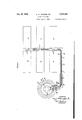
- FIG. 1 is a diagrammatic view illustrating a milking system provided by my invention, in-
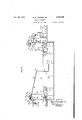
- Fig. 2 is a diagrammatic view of the moving platform and certain associated parts embodying features of the invention.
- Fig. 3 is an enlarged vertical sectional view taken on line 33 of Figure 2.
- Fig. 4 is a. view in side elevation, with the platform in vertical section, looking in the direction of the arrows 4 in Figures 3 and 5'.
- Fig. 5 is a plan view of a portion of the moving platform and certain associated parts, taken is.
- Fig. 6 is a detail view in vertical section, on line 6-6 of Fig. 5.
- Fig. 7 is an enlarged vertical sectional view of a detail, taken on line 'l---! of Fig. 5.
- Fig. 8 is an enlarged fragmentary side-elevational view, looking in the direction of the arrow 8 in Fig. 2.
- Fig. 9 is an enlarged detail View partly in plan and partly in horizontal section, taken on line 9-9 of Fig. 3. g
- Fig. 10 is a detail viewtaken on line Ill-l0 of Fig. 9.
- Fig. 11 is a diagrammatic view illustrating the platform in conjunction with certain trip devices and other parts embodying features of the invention.
- Fig. 12 is a diagrammatic view, the left hand portion of which is taken along the left hand section line designated I2 in Figure 11, and the right hand portion of which is taken along the right hand section line I2 of said Fig. 11.
- Fig. 13 is a diagrammatic view showing various features associated with the platform, including electrical connections for controlling gates in the walk-way from the barns to the platform.
- Fig. 14 is a plan view showing one of the walkway gates and certain associated parts.
- Fig. 15 is a side elevational view of the construction shown in Fig. 14.
- Fig. 16 is a detail View in vertical section, on line l6--I6 of Fig. 15. a
- Fig. 1'7 is a vertical sectional detail view showing a pneumatically-controlled piston mechanism.
- Fig. 18 is a vertical sectional detail view showing solenoid-valve'means adapted to control a walk-way gate.
- Fig. 19 is an enlarged vertical sectional detail view of a swivel joint for the vacuum and pulsator lines.
- FIG. 1 a system which may be utilized in the practice of my invention is illustrated diagrammatically in Figure 1, where two series of barns are designated as I 0, H, and are connected by walk-ways l2 and IS with a moving platform M.
- the latter as shown, may be of annular form and may be surrounded by an area l5 for workmen and attendants. Where the milking of the cows is to be exhibited to the public, an amphitheater comprising a plurality of zones for visitors may be provided,
- a glass partition 15 may separate the visitors zones from the workmens space l5.
- the Walkway l2 through which the cows pass from the barns to the platform or table l4 may be provided with a series of gates designated a-h, respectively, which are operated in "timed relation to the movement of the table l4 as hereinafter more specifically described.
- the walk-way 13 provides for the return of the cows from the table 14 to the barns.
- the zones l5, l6, l1, and 18, may, as shown, be of substantially annular form, each of said zones terminating adjacent a region bounded by suitable walls l9, 19', through which region pass the aforementioned walkways 12 and I3,
- the moving annular platform or table 14 may extend over an excavation, as shown in Figure 12, and may comprise flooring mounted on beams 20 (Fig. 3) disposed radially around said platform and secured at their inner and outer ends to channel girders 2
- a pair of concentric rails or tracks 23, 24 are secured to the under sides of the beams 20 by suitable clamping .devices 25, 26, andsaid rails are designed to rest upon two concentric series of wheels 21, 23 (Figs. 3 and 12) which are properly mounted in order to constitute means for supporting the table 14 for rotary travel.
- Said rails may be ordinary railroad rails and the wheels similar to railroad car wheels.
- the table is elevated some distance (about two feet, for example) above the workmens area 15, as shown in Figures 6 and 12; the space between said area and said table being surrounded by a suitable wall such as indicated at I4.
- the walkways 12 and 13 may be on the ground level and the platform 14 may also be positioned on said ground level; the workmens area 15 being below said platform as previously stated, but above the bottom of the excavationbeneath said platform.
- the wheels aforesaid may be journaled in series of pedestals 29, mounted on supports 3!, 32, which may be of reinforced concrete, in the aforementioned excavation.
- Two of said wheels 28, preferably diametrically opposite, are positively driven by motors, through any suitable connections of conventional form, in casings 33, 33 (Fig. 13).
- the pedestals or bearings 38 may be yieldingly mounted in any well known or approved form. Such mounting may also be provided for the bearings or pedestals that carry the wheels 21, if desired.
- the upper surface of the platform I 4 has a circumferential series of stalls, designated 34, disposed successively or in tandem relation to each other, as shown in Figure 2.
- These stalls may, as shown in Figures 2-5, be formed by inner and outer circumferential frames; the inner frame comprising vertical pipes 35a suitably fixed to the table 14 and carrying three circumferential series of horizontal pipes designated 35, 35', and 35".
- the outer frame similarly comprises vertical pipes 36a fixed to said table and carrying a circumferential series of upper pipes 35.
- Sets of pipes 36' and 36" are also positioned between and carried by certain of said vertical pipes 36a below the pipe 35; it being noted, however, that pipes 36' and 36" are omitted from the space between a pair of the vertical pipes 36a. in each stall, thus permitting a cow to enter the stall readily from the walkway l2, as indicated in Figure 2.
- Each stall also includes a grating 31 in the floor of the rotary platform for enabling manure to pass therethrough into a stationary gutter 38.
- the latter comprises an annular channel suitably mounted beneath said platform and communicating with a sewer through suitable pipes such as shown at 39 (Fig. 3).
- Inclined blades 46 ( Figure 6) attached to the under side of platform 14 adjacent the respective gratings 31, guide and deflect the manure into the gutter 33.
- the inner and outer circumferential pipes 35, 33 of the stall frames are connected by a series of transverse pipes 41 which impart rigidity to said frames and which may also support a vacuum pipe line 42.
- the cows may be milked in their respective stalls in any desired manner.
- the milking may be controlled automatically by means such as disclosed in the Hapgood Patent No. 1,787,152, dated December 30, 1930, or in any other well-known way.
- Each of the stalls may be provided for this purpose with a milking machine of well known construction ( Figure 8) comprising teat cups 43 and tubes 44, one of which tubes is connected to a milk receiving jar 45 and the other two of which are connected to vacuum and pulsation means as will be readily understood. Since means is Well-known (as in said Hapgood patent) for controlling said apparatus to milk the cow during a portion of the rotation of the platform and to cause said milk to be delivered to said jar, said means need not be here described in detail.
- means such as shown in said patent may be provided for controlling, during the travel of the platform, the discharge of the milk from the successive jars as they pass a given point, and for cleaning the teat cups, milk jar and connected milk tube of each milking unit by drawing water therethrough upon passing another station.
- each stall is shown provided with a set of valves, such as indicated at 46, 41, and 48 ( Figures Hand 12) which are operated during the travel of the platform by suitable stationary trip devices, such as 49, 53, and 5
- a trough 52 of tank 53 Upon arrival opposite a trough 52 of tank 53 (Fig. 12) one of said valves is operated to cut off vacuum from the associated jar 45 and to connect said jar with the atmosphere, as a result of which the milk in said jar is discharged into said tank 53.
- the latter is mounted on a scale 54.
- the valve-operating trips adjacent said tank troughs 52 are carried by a stationary frame 55. From the scale-tank 53 the milk may be passed into a storage tank 53'.
- a series of water tanks 56 ( Figures 11 and 12) is providedalong a portion of the rotating table 14, said tanks being suitably supported on stationary framing 51.
- the latter also carries trip devices, as shown, for actuating the valves 43, 41, and 48 of the respective sets during the rotation of the table.
- the teat cups 43 in each stall are carried, when not in use, by an arm 53 pivoted at one end to one of the vertical frame pipes 36a.
- Each of said arms instead of being actuated directly by a trip as in said Hapgood patent, may, as shown. be connected to a rod of a piston (not shown) in a cylinder 59, which cylinder may be connected altern'ately'to vacuum and to the atmosphere by operation of one of the associated valves 46, 41, 43.-
- the trips carried by the frame 51 are so arranged that as each milking apparatus passes thereunder, the arms 58 carrying the teat cups of said apparatus is raised from the lower position shown in the right hand portion of Figure 12, into the upper position shown in the left hand portion of said figure. Thereby the respective teat cup carrying arms are raised to clear the water tanks 56.
- trip devices carried by theframe 57 may, as shown. be connected to a rod of a piston (not shown) in a cylinder 59, which cylinder may be connected altern'ately'to vacuum and
- said trip means operates to cut on the vacuum connection to the jar &5 as a result of which the water is dumped therefrom into the compartment 55b, and at about the same time the arm 58 is raised into its upper position.
- thecow may be dried by hot air, as in said I-Iapgood and Luks patents, and also massaged if desired.
- the operator may apply the teat cups of the milking apparatus to the cow; after which the proper valves are operated, either manually or automatically by trip devices, to cause operation of the milking unit and drawing of the milk from the cow to the jar 45.
- the teat cups are detached from the cow, hung on the arm 58, and, upon the arrival of the jar 45 opposite the trough 52, the milk is discharged into said trough as noted above.
- a pair of vacuum or exhaust pumps Gil ( Figures 12 and 13) connected to a pipe 6
- the milking machines may be employed in a pneumatic pulsating system such as shown in the Forsyth Patent No. 1,257,688, dated February 25, 1918, or in a pneumatic electric pulsating system, as disclosed in the Daysh and Hapgood Patent No. 1,405,104, dated January .31, 1922, or any other suitable system.
- ] are shown as of the type tro-magnetic pulsator control means in the stalls on said table and is carried by the pipe 63; said line or cable also extending into the swivel joint 62.
- Said swivel joint may take any convenient form, such as illustrated in Fig. 19, wherein a plurality of concentric conducting rings 12" are carried by and suitably insulated from a housing extension '63 of the rotating pipe 63.
- has fixed thereto a disk 6 I which carries a plurality of brushes 'H suitably insulated from said disk and engaging the respective ringslZ".
- the two pulsators 10 supply current impulses to a pair of wires H in the cable Hyand said impulses are transmitted through the corresponding pair of brushes 1! and rings 12 to a pair of the wires I2, which are in the cable 12.
- the return portion of the impulse circuit may be by ground
- the wire 700 may be included in the cable 12, while wire Till may be included in cable H.
- the swivel joint may include a bearing 193 between a shoulder 764 of housing 63' and a flange H35 on the stationary pipe 6
- may extend into pipe 63 above said bearing as shown,ywith a snug fit,
- each milking unit may comprise an electro-magneticv valve such as shown in said Daysh and Hapgood patent, No. 1,405,104, to which electric impulses are sent over one of the wires 12', said valve being connected to the vacuum line 42 and also to one of the pipes 44 of said milking unit, so
- Thatpulsations are supplied to the teat cups in a convenient and well-known'manner.
- each of the stalls 34 is provided with a gate T L-suitably hinged on one of the vertical frame standards 35a. Also, each stall is provided with a pair of stanchions 8
- Each of the stanchions 8I, 8I in a stall is pivotally connected to and supported by an adjacent frame element. As shown in Figure 3, one of said stanchions is pivotally connected to a pair of link members 82, 82, which in turn are pivotally mounted on the horizontal frame pipes 35', 39". The other of said stanchions is pivotally connected to similar link members 83, 83,
- a series of frames 88 Secured to the bottom of the table I4 are a series of frames 88, each below a corresponding one of the stalls 34. Also suitably suspended from the bottom of said table I4 is a vacuum pipe 89, connected by a' pipe 90 (Fig. 4) with the upper vacuum pipe 42.
- Each of the frames 88 has suitably fastened thereto and depending therefrom a valve casing 9I containing a rotatable valve'92 (Fig. 9).
- Piping 93 connected to the vacuum pipe 89 communicates through port 94 with the interior of said casing 9
- Another port 95 in said casing is open to atmosphere. with a port 91 in said casing and is connected to a T-shaped fitting 90 ( Figures 3 and 4).
- Each frame 88 has pivotally mounted on the bottom thereof a cylinder 99 containing a piston 09 (Fig. 1'1) which is urged into its upper posi-v tion by a spring 99", and also a cylinder I containing a similar piston and spring. At their upper ends said piston chambers are open to the atmosphere as indicated at 99' in Fig. 17.
- the rods ItI, I02 of said pistons are pivotally connected to opposite ends, of a lever I03.
- the latter as shown, has a curved end I03 adapted to bear against the lower side of a plate I04 as a fulcrum during the movements of said lever tc and from the dotted line position in Figure 4.1
- a link I06 is connected at one end to an intermediate portion of said lever I03 and at its opposite end to the previously mentioned stanchion-actuating lever 81.
- a link I01 Connected to the piston rod I02 is a link I01 which is also connected at I08 to a toggle comprising a pair of links I09, H0.
- the toggle link I09 is pivotally mounted on one of the vertical pipes 352.
- link H0 is pivotally connected at one end to said link I09 and at its other end. through the swivel joint III, to an extension of an arm II2 which is pivotally supported on another of said pipes 35a.
- the gate 14 is open, so that the cow in the stall (to the left of said gate in Fig. 5, corresponding to the stall at the right of said gate in Figure 2) is free to leave the stall and to enter the exit walkway I3.
- the piston rod I02 and link I01 are raised and the toggle links I09, IIO are in the elevated position shown in Figures 4 and 5. however, the piston in the cylinder I00 is moved downwardly, it will be apparent that the toggle I09-I I0 will be straightened and the gate 14 thereby closed.
- is connected to a T-shaped pipe coupling 98.
- One end of the horizontal portion of said coupling communicates through flexible tube II5 with the interior of the piston chamber I00 through the bottom of said chamber.
- the other end of said horizontal portion of coupling 98 communicates through a flexible tube I I6 with a port H1 (Fig. '1) in a casing II8 ( Figures 4 and 7) containing a valve which is operated by a hand lever II9,
- a flexible tube I communicates at its lower end with the interior of piston chamber 99, through the bottom of said chamber, and communicates at its upper end with a port I2I in said valve casing H8.
- Said casing II8, as shown in Figure 5 is suitably carried by one of the vertical pipes 36a.
- the valve casing H6 and mechanism therein are of well-known type.
- the mechanism includes a diaphragm I22 which extends across the interior of the casing, and a plunger I23 having an extension I23 passing through said diaphragm and resting at its lower end on a disk I24, said extension being clamped to said diaphragm between a nut I25 and an annular flange I26 on said extension.
- the 'disk I24 is urged upwardly by a spring I21.
- the lower end of said casing supports a container I28 open at its bottom to the atmosphere and filled with cotton,
- the plunger extension I23 is hollow, to provide communication between opposite sides of the diaphragm I22, and is also cut away at its side portions above said diaphragm as shown at I30.
- Disk I24 now seats against the lower end of the hollow plunger extension I23, cutting off communication between ports H1 and I2I.
- the port IZI is now open to atmosphere by way of container I28, passage I3I between guiding lugs for disk I24 in casing H8, and opening I32 in partition I33.
- plunger I23 is raised in casing H8, through well-known cam mechanism (not shown) relieving the spring I34.
- Disk I24 follows into the dot-dash line position, wherein it is seated on the lower surface'of the flange I35 surrounding the opening I32, thereby shutting off atmosphere from the portion of the casing above said opening I32.
- Plunger I23 is raised further by said turning of handle Il9, leaving disk I24 seated, and placing port H1 in communication with port I2I, through the path indicated by dotted arows; i. e., through the lower exit walkway I3.
- each valve casing 91 has integral therewith a guide comprising a pair of bars I48,
- valve 92 is ,ele- 'vated into the position shown inj Figures 3, g, :and 5, and said gate 14 isopened.
- the tube IIB andport I,I:I,of valve casing H8 are also in communication with :atmosphere, and since valve handle I I9 isgatothis time in the dotted line position (Fig. ,-so':that
- ports II! and I2I arein communication with SI .in stall' .A larev result of which th pisto i said ham er m ves downwardly and draws with it the rod IO'Lthereby clos n t e ate 14,.
- valve 9 into sa d dot d line position in Figure 9 also connects to vacuum the tube l5 and port II! of the hand-valve casing I;I8. Zi'his. however, has no effect upon the piston- 99,0111.
- cy i d sin e he valve and e H19 at this t me in th po i i n s own in Fi res 5 and. 71' an th plun r .3 and a s c ed parts are ,theposition shown in full lines in Fig.
- F7, :Vllhoneindhk 124 is engaged by plunger extension 11 .
- a dthe latter port is now moving into the position ,formerly occupied by stall ;B, are ,operated to ,set position by the aboveementionedlower n of p s rod 1 2 to close :the gate.
- , and gate I4 has been described specifically in conjunction with only one of the stalls 94, it will of course be understood that each stall is provided with a duplicate of the gate and stanchion operating mechanism above described, including a trip valve 92, hand-valve H8, and connections to a pair of chambers 99, I00, for actuating its stanchions and gate at appropriate times during the rotation of table I4, in the same manner as hereinbefore specified.
- each of the hand levers H9 of the respective valves H8 might be turned by a stationary trip device from its dotted to its full line position (Fig. 5) during rotation of the table I4, said trip device being so located as to actuate said lever at a suitable point in the rotation of the table which is passed by the stall after the cow has departed therefrom and before the stall is in position for receiving another cow.
- each of said levers H9 might be operated, by another stationary trip device, from the full to the dottedline position above mentioned, at an appropriate point in the rotation of the table, for automatically controlling the shifting of the stanchions from *set to closed position. It is preferred, however, to 0perate each of said levers H9 by hand, especially for moving the stanchions from set to closed position, so that such operation will not occur until the attendant has ascertained that the cow is in the proper position.
- I20 is placed in communication with the atmosphere through the bottom of container I29; and thereupon the piston in cylinder 99 will be raised into its uppermost position, shifting the stanchions from closed to -set position, so that a cow may insert its head and neck betweenbaid stanchions, as previously described.
- Each'oi the pipes 93 connecting the vacuum line 89 to the respective valve casings 9I may be provided with a throttling valve 93' (Fig. 4) which may be set to soften the closing action of the gate and stanchions as desired.'
- Rubber stop elements I4, 14" (Fig. 5)- are provided in each stall for engagement by the associated gate I4 in its respective open and closed positions.
- Each stall 34 may also include an illuminating unit of well-known type comprising a source of light below a transparent or translucent plate I42 (Fig. 2) which unit is set flush with the platform and provides illumination for showing the cow to advantage when the apparatus is being exhibited for public instruction or entertainment.
- said light unit may be so positioned as to be under the cow's udders, for illuminating especially the milking operation.
- a plate I43 (Fig. 8) displaying the name of the cow may also be supported on vertical bars I44 extending between the rods 36, 36" of the outer framework of each stall.
- a door I45 covers an opening through which the stationary manure gutter 38 may be thoroughly cleaned.
- the cleaning may be accomplished, for example, by inserting a broom or like implement through said opening into engagement with said gutter, said broom being carried around said gutter by the rotation of the table I4.
- cows pass from the barns to the rotary table I4 along a walk-way I2.
- Means are provided for controlling the passage of the cows through said pathway in timed relation to the travel of the table, ,which means may be constructed'substantially as follows:
- Said walk-way is provided at its sides with guide frames I50, I5I (Fig. 14) each of which may comprise horizontal rails or pipes suitably supported by vertical pipes I52 (Fig. '15).
- guide frames I50, I5I Fig. 14
- each of said gates may be pivotally supported by a corresponding one of the vertical rods or pipes of the guide frame I50.
- each of said walk-way gates Connected to each of said walk-way gates for operating the same is a corresponding one of a series of piston chambers I53, each of which may be pivotally carried in any convenient manner by an adjacent one of the vertical pipes I52
- each cylinder I53 may be pivotally supported by an arm I54 carried by another arm I55 secured to and projecting laterally from a vertical frame pipe I52.
- Each cylinder I53 may contain a piston and spring arranged in the same manner as in cylinder 99 (Fig. 17).
- the rod I56 of each of said pistons is connected to the corresponding walkway gate in any suitable manner as through links I51 '(Figs. 14 and 15), and'extension I55 of a lever I58 rotatably mounted on a frame pipe I 52, which lever has a slot engaged by a pin I59 depending from the associated gate.
- Adjacent each cylinder I53 is a solenoid-valve unit arranged to control the operation of the cylinder.
- said unit may comprise a casing I60 having ports IGI, I62 adapted to be opened and closed by valves I63, I64 carried byjand movable with a bar I65.
- Pivoted in said-casing and extending through a slot in said bar is a lever I66 which is connected to the arm I'6I'of a'solenoid core I68 in said casing', the winding I69 of which core may be wound around the corresponding portion of the casing and may be energized and deenergized at appropriate times as hereinafter described.
- Each valve I63, I64 is engaged by a corresponding one of a pair of springs I10, I1I, each of which springs is compressed by movement of its valve to open the associated port I6I or I62.
- a chamber I13 open at one end to the atmosphere, and containing cotton or other suitable filtering material, is mounted at its other end in a wall of a chamber I14 above the valve I63 and is in communication with said chamber.
- a pipe I16 which communicates with said chamber and also with a vacuum pipe I11. The latter extends along one side of the walkway and is connected to any suitable source of vacuum supply, as, for example, the pumps 60.
- a tube I18 communicates with the interior of casing I60 as shown in Fig. 18 and extends into communication with a port in a hand-valve casing I80.
- the latter, and the parts therein, are of well-known construction and may be the same as illustrated in Fig. '7 and previously described herein.
- Also communicating with a port in said valve casing I80 is a tube I8I which also communicates through an end of cylinder I53, with the space in said cylinder behind the piston therein.
- the ports in the casing I80, with which the tubes I18, I8I, communicate, correspond with ports II1, I20, respectively of the aforementioned casing H8; and the handle I88 is normally in such position as to establish communication between said tubes, through said ports, in the same manner that communication between tubes H6 and I20 is established through ports H1 and I2I aforesaid when the handle H8 is in the normal or dotted line position shown in Fig. 5.
- communication between tube NH and the atmosphere, by way of chamber I80" (corresponding to chamber I28 of casing H8) is cut off in the same manner as hereinbefore described with respect to tube I20 and chamber I28.
- valve is provided to enable the operation of the gate to be controlled manually independently of the automatic control through solenoid winding I69. open a walk-way gate, even though the corresponding solenoid winding IE8 is de-energized, the valve handle I80 is turned to bring the valve mechanism into the position shown in connection with valve H8 in Fig. '7, as the result of which communication between tubes I18 and I8I is blocked and tube I8I is connected to atmosphere. Atmosphere is thereby supplied through tube I8I to cylinder I53 andthe gate is opened.
- valve mechanism Upon thereafter returning said valve handle into its normal position, the valve mechanism is restored into such position as to cut off atmosphere from tube I8I and to establish communication between said tube and tube I18, restoring the control of solenoid winding I over the walkway gate, and causing closing of the latter if said solenoid is de-energized.
- a hand valve I80 may be provided for each walk-way gate, between its corresponding solenoid-valve I and cylinder I53.
- Suitable rubber stops I82, I83 may be provided for each walk-way gate, as shown in Figure 14, for engagement by the gate in its open and closed positions, respectively.
- a stationary rail I85 (Fig. 13.), which supports a series of circuit closers 585, one for each of the walk-way gates. 'One terminal of each circuit closer is connected by wire I81 to current main I88, while the other terminal is connected through a wire I with a terminal of one or more of the solenoid windings I551. The other terminal of each solenoid winding is connected to a wire I9I which in turn is connected to current main I89.
- Said circuit closers I85 are of any suitable well-known construction, and each includes an arm adapted to be engaged and operated to circuit closing position by shoes I82 carried by frames 88 on the bottom of the table I4 androtating therewith.
- Fig. 13 For convenience in description, the solenoids shown in Fig. 13 are designated I69a-I89h, respectively, to identify the respective gates which they control, while the circuit closer arms are respectively designated a--.g'.
- One circuit-closer operating shoe I82 is provided for each stall 34 on the table It.
- said shoe I92 passes beyond said arm a, whereupon the circuitthrough solenoid I591; is broken and gate it closes.
- said shoe I691) causing gate 1) to open and enabling a cow behind said gate to pass into the space behind More particularly, if it is desired to gate a; said gate b thereafter closing when said shoe I92 passes out of engagement with arm 2).
- said shoe I92 operates successively the circuit closer arms c'-g, energizing and deenergizing successively the respective solenoids I69cIIi9g, and permitting the cows behind the gates cg to pass into the respective spaces ahead of said gates.
- shoe I92 of the next stall 34 operates arm at, opening gate a to permit the cow behind said gate to pass into said next stall, after which the foregoing cycle is repeated as rotation of table I4 proceeds.
- circuit closer arm a by a shoe I92 energizes not only the solenoid I69a but also the solenoid I69h, so that-gate h is opened at the same time as gate a to enable a cow to advance therethrough.
- each of the pistons in the cylinders I53 may be connected to its respective walk-way gate through toggle links in the same way in which each of the pistons in cylinders IE is connected to the corresponding stall gate I4.
- the rotation of the table I4 while continuous, is sufiiciently slow to enable the performance of the milking and other operations above-described, and also to enable the cows to pass safely from the walk-way I2 into the respective stalls, as well as to depart from said stalls on to the walk-way I3, during the rotation of said table.
- Each cow is washed, dried, and milked during its travel on said table from the entrance to the exit walk-way. It will be noted that the cows depart from the rotating table I4 on the same side as that from which they entered. their stalls, Without the necessity of crossing above or below the table.
- the tandem arrangement of the stalls not only enables the cows to enter and depart from the table M on the same side of the latter, but also provides the public with a full side view of the cows during the milking and other operations which take place during the rotation of the table.
- the gates I4 and stanchions 8i, and their operations as above described the positioning of the cows in the stalls and their egress therefrom are effectively regulated in appropriate relation to the rotation of the table I4.
- the passage of the cows toward said table is at the same time controlled in coordination with the rotation of the table, through the shoes I92 and solenoid-valves associated with the walk-way gates.
- the supporting of the vacuum pumps and pulsators in the excavation and the leading of vacuum and electric impulses therefrom to the apparatus on the rotating table through the swivel joint 62 avoids the necessity of carrying said pumps and pulsators with the rotating table and simplifies its construction and operation.
- Apparatus for treating the animals of a group in succession comprising a movable platform, means for moving the same, stalls on said platform, each of said stalls comprising framework secured to said platform and a gate movably supported by said framework, vacuum-producing means, means connected to said vacuum-producing means for milking said animals while in said stalls, means connected to said vacuum-producing means for operating said gates successively, and means controlled by movement of said platform for controlling said gateoperating means.
- Apparatus for treating the animals of a group in succession comprising a movable platform, means for moving said platform, stalls on said platform, stanchions in said stalls, and means controlled by movement of said platform for controlling operation of the stanchions in the successive stalls.
- Apparatus for treating the animals of a group in succession comprising a movable platform, means for moving said platform, stalls on said platform, stanchions in said stalls, means controlled by movement of said platform for controlling operation of the stanchions in the successive stalls to a given position, and manual means for controlling movement of said stanchions to another position.
- Apparatus for treating the animals of a group in succession comprising a movable platform, means for moving said platform, stalls on said platform, stanchions in said stalls, and means controlled by movement of said platform for opening the stanchions in the successive stalls as said stalls pass a given point and for moving said stanchions toward closed position as said stalls pass another point.
- Apparatus for treating the animals of a group in succession comprising a movable piatform, means for moving said platform, stalls on said platform, stanchions in said stalls, means controlled by movement of said pla'tformfor opening the stanchions in the successive stalls and for moving said stanchions to partially-closed position, and manual means for controlling movement of said stanchions to fully closed position.
- Apparatus for treating the animals of a group in succession comprising a movable platform, means for moving said platform, stalls on said platform, stanchions in said stalls, gates for said stalls, and means controlled by'movement of said platform for controlling
Landscapes
- Life Sciences & Earth Sciences (AREA)
- Environmental Sciences (AREA)
- Zoology (AREA)
- Animal Husbandry (AREA)
- Biodiversity & Conservation Biology (AREA)
- Dairy Products (AREA)
Description
1942. H. JEFFERS, SR
DAIRY APPARATUS Filed July 5, 1940 12 Sheets-Sheet l w Q N x u N5 Q 4 iv Q R (F s5. |r=\|.
INVENTOR ATTORNEY Dec. 15, 1942.
H. W. JEFFERS, SR
DAIRY APPARATUS Fil edJuly 5 1940 12 Sheets-Sheet 2 INVEN'I 'OR Mm ATTORNEY Dgq. 15, 1942. w. JEFFERS, SR
DAIRY APPARATUS Filed July 5, 1940 12 Sheets-Sheet 3 ILNVENTOR ATTORNEY Dec. 15, 1942.
H. w. JEFFERS, sR DAIRY APPARATUS Filed July 5, 1940 12 Sheets-Sheet 4 INVENTOR ATTORNEY Dec. 15, 1942. H. w. JEFFERS; sR
DAIRY APPARATUS l2 Sheets-Sheet 5 Filed July 5, 1940 INVENII'OR I v ATTORNEY Dec. 15, 1942. H. W.-JEFFERS, SR 2,305,259
DAIRY APPARATUS Filed July 5, 1940 12 Sheets-Sheet e INVENTOR BY i ' ATT'O-RNEY Dec. 15, 1942. H; w. JEFFERS, SR
DAIRY APPARATUS Filed July 5, 1940 12 Sheets-Sheet 7 LL\ LJ L( l v ATTORNEY Dec. 15, 1942. H. w. JEFFERS, SR
' DAIRY APPARATUS Filed July 5," 1940 12 Sheets-Sheet s INVENTOR y m ATTORNEY Dec. "15, 1942. H. w. JEFFERS, SR
DAIRY APPARATUS Filed July 5, 1940 12 Sheets-Sheet 9 & R hh INVENTOR mm Q ATTORNEY Dec. 15, 1942. V H. w. JEFIFE'RSI, SR: 2,305,259
DAIRY AP'BARATUS Filed July- 5, 1940 12 she ts-sheet 1o INVENTOR- ATTORNEY Dec. 15, 1942. -.-H. w. JEFFERS, SR
' DAIRY APPARATUS Filed July 5, 1940 l2 Sheets-Shee't- 12 gm, IIINYENTOR "2m I 1 4 6 U 7 w M u 1 H WW n Y J 3 5 3 0 m H, M fl 7 a a z r w "2 W1 7 6 1 m .m m; n. w 9
ATTO R N EY Patented Dec. 15, 1942 DAIRY APPARATUS Henry William Jeffers, Sn, Plainsboro, N. 3., as-
signor to The Borden Company, New York,
N. Y., a corporation of New Jersey Application July 5, 1940, Serial No. 344,087
37 Claims.
This invention relates to a dairy system and has for an object the provision of novel and efficient means which enables. cows to pass successively on to a moving platform and to be subjected to the operations incident to hygienic milking while traveling with said platform.
A feature of the invention comprises a rotary platform or turntable having provisions for receiving the cows in tandem relation, and for enabling them to be milked and subjected to other operations while in that relation on said platform.
The invention further provides a new and advantageous arrangement of stalls, including gates and stanchions and means for automatically controlling the operation thereof at appropriate times during the movement of the platform.
In addition, the invention provides for controlling the passage of the cows from their barns to the platform in timed relation to the travel of the latter.
Still another feature of the invention comprises novel and effective means for supplying vacuum and power to the moving platform.
The invention further provides a rotary milk-g ing platform which is not only highly eiiicient and presents the advantages above indicated, but is also considerably cheaper to construct than the rotary milking tables heretofore employed and which furthermore enables the milking and other operations to be displayed to the public in a particularly distinctive and appealing manner.
Other features and advantages of the invention will be hereinafter described and claimed.
In the accompanying drawings, which illustrate a practical embodiment of the invention: Fig. 1 is a diagrammatic view illustrating a milking system provided by my invention, in-
cluding barns, walk-ways, and moving platform. 4.:
Fig. 2 is a diagrammatic view of the moving platform and certain associated parts embodying features of the invention.
Fig. 3 is an enlarged vertical sectional view taken on line 33 of Figure 2.
Fig. 4 is a. view in side elevation, with the platform in vertical section, looking in the direction of the arrows 4 in Figures 3 and 5'.
Fig. 5 is a plan view of a portion of the moving platform and certain associated parts, taken is.
on line 5-5 of Fig. 4.
Fig. 6 is a detail view in vertical section, on line 6-6 of Fig. 5.
Fig. 7 is an enlarged vertical sectional view of a detail, taken on line 'l---! of Fig. 5.
Fig. 8 is an enlarged fragmentary side-elevational view, looking in the direction of the arrow 8 in Fig. 2.
Fig. 9 is an enlarged detail View partly in plan and partly in horizontal section, taken on line 9-9 of Fig. 3. g
Fig. 10 is a detail viewtaken on line Ill-l0 of Fig. 9.
Fig. 11 is a diagrammatic view illustrating the platform in conjunction with certain trip devices and other parts embodying features of the invention.
Fig. 12 is a diagrammatic view, the left hand portion of which is taken along the left hand section line designated I2 in Figure 11, and the right hand portion of which is taken along the right hand section line I2 of said Fig. 11.
Fig. 13 is a diagrammatic view showing various features associated with the platform, including electrical connections for controlling gates in the walk-way from the barns to the platform.
Fig. 14 is a plan view showing one of the walkway gates and certain associated parts.
Fig. 15 is a side elevational view of the construction shown in Fig. 14.
Fig. 16 is a detail View in vertical section, on line l6--I6 of Fig. 15. a
Fig. 1'7 is a vertical sectional detail view showing a pneumatically-controlled piston mechanism.
Fig. 18 is a vertical sectional detail view showing solenoid-valve'means adapted to control a walk-way gate.
Fig. 19 is an enlarged vertical sectional detail view of a swivel joint for the vacuum and pulsator lines.
Referring to the drawings, a system which may be utilized in the practice of my invention is illustrated diagrammatically in Figure 1, where two series of barns are designated as I 0, H, and are connected by walk-ways l2 and IS with a moving platform M. The latter, as shown, may be of annular form and may be surrounded by an area l5 for workmen and attendants. Where the milking of the cows is to be exhibited to the public, an amphitheater comprising a plurality of zones for visitors may be provided,
as indicated at l6, I1, and [8, said visitors zones surrounding the workmens area l5 and being positioned at progressively increasing heights. A glass partition 15 may separate the visitors zones from the workmens space l5.
The Walkway l2 through which the cows pass from the barns to the platform or table l4 may be provided with a series of gates designated a-h, respectively, which are operated in "timed relation to the movement of the table l4 as hereinafter more specifically described. The walk-way 13 provides for the return of the cows from the table 14 to the barns.
The zones l5, l6, l1, and 18, may, as shown, be of substantially annular form, each of said zones terminating adjacent a region bounded by suitable walls l9, 19', through which region pass the aforementioned walkways 12 and I3,
as well as a passage 19" to the workmens space The moving annular platform or table 14 may extend over an excavation, as shown in Figure 12, and may comprise flooring mounted on beams 20 (Fig. 3) disposed radially around said platform and secured at their inner and outer ends to channel girders 2|, 22 (Figures 3 and 12) which are suitably curved to conform to the shape of the platform. A pair of concentric rails or tracks 23, 24 are secured to the under sides of the beams 20 by suitable clamping . devices 25, 26, andsaid rails are designed to rest upon two concentric series of wheels 21, 23 (Figs. 3 and 12) which are properly mounted in order to constitute means for supporting the table 14 for rotary travel. Said rails may be ordinary railroad rails and the wheels similar to railroad car wheels. Preferably, the table is elevated some distance (about two feet, for example) above the workmens area 15, as shown inFigures 6 and 12; the space between said area and said table being surrounded by a suitable wall such as indicated at I4.
The walkways 12 and 13 may be on the ground level and the platform 14 may also be positioned on said ground level; the workmens area 15 being below said platform as previously stated, but above the bottom of the excavationbeneath said platform.
The wheels aforesaid may be journaled in series of pedestals 29, mounted on supports 3!, 32, which may be of reinforced concrete, in the aforementioned excavation. Two of said wheels 28, preferably diametrically opposite, are positively driven by motors, through any suitable connections of conventional form, in casings 33, 33 (Fig. 13). To prevent slippage between the wheels and rail in the drive, the pedestals or bearings 38 may be yieldingly mounted in any well known or approved form. Such mounting may also be provided for the bearings or pedestals that carry the wheels 21, if desired.
The upper surface of the platform I 4 has a circumferential series of stalls, designated 34, disposed successively or in tandem relation to each other, as shown in Figure 2. These stalls may, as shown in Figures 2-5, be formed by inner and outer circumferential frames; the inner frame comprising vertical pipes 35a suitably fixed to the table 14 and carrying three circumferential series of horizontal pipes designated 35, 35', and 35". The outer frame similarly comprises vertical pipes 36a fixed to said table and carrying a circumferential series of upper pipes 35. Sets of pipes 36' and 36" are also positioned between and carried by certain of said vertical pipes 36a below the pipe 35; it being noted, however, that pipes 36' and 36" are omitted from the space between a pair of the vertical pipes 36a. in each stall, thus permitting a cow to enter the stall readily from the walkway l2, as indicated in Figure 2.
Each stall also includes a grating 31 in the floor of the rotary platform for enabling manure to pass therethrough into a stationary gutter 38. The latter comprises an annular channel suitably mounted beneath said platform and communicating with a sewer through suitable pipes such as shown at 39 (Fig. 3). Inclined blades 46 (Figure 6) attached to the under side of platform 14 adjacent the respective gratings 31, guide and deflect the manure into the gutter 33.
The inner and outer circumferential pipes 35, 33 of the stall frames are connected by a series of transverse pipes 41 which impart rigidity to said frames and which may also support a vacuum pipe line 42.
The cows may be milked in their respective stalls in any desired manner. For example, the milking may be controlled automatically by means such as disclosed in the Hapgood Patent No. 1,787,152, dated December 30, 1930, or in any other well-known way.
Each of the stalls may be provided for this purpose with a milking machine of well known construction (Figure 8) comprising teat cups 43 and tubes 44, one of which tubes is connected to a milk receiving jar 45 and the other two of which are connected to vacuum and pulsation means as will be readily understood. Since means is Well-known (as in said Hapgood patent) for controlling said apparatus to milk the cow during a portion of the rotation of the platform and to cause said milk to be delivered to said jar, said means need not be here described in detail. Likewise, means such as shown in said patent may be provided for controlling, during the travel of the platform, the discharge of the milk from the successive jars as they pass a given point, and for cleaning the teat cups, milk jar and connected milk tube of each milking unit by drawing water therethrough upon passing another station.
Since means for controlling the above-mentioned operations during rotation of the platform or table l4 are known in the art, said means need not be specifically described herein. It may be noted, however, that each stall is shown provided with a set of valves, such as indicated at 46, 41, and 48 (Figures Hand 12) which are operated during the travel of the platform by suitable stationary trip devices, such as 49, 53, and 5| for accomplishing the functions above indicated at the proper times.
Upon arrival opposite a trough 52 of tank 53 (Fig. 12) one of said valves is operated to cut off vacuum from the associated jar 45 and to connect said jar with the atmosphere, as a result of which the milk in said jar is discharged into said tank 53. The latter is mounted on a scale 54. The valve-operating trips adjacent said tank troughs 52 are carried by a stationary frame 55. From the scale-tank 53 the milk may be passed into a storage tank 53'.
A series of water tanks 56 (Figures 11 and 12) is providedalong a portion of the rotating table 14, said tanks being suitably supported on stationary framing 51. The latter also carries trip devices, as shown, for actuating the valves 43, 41, and 48 of the respective sets during the rotation of the table.
The teat cups 43 in each stall are carried, when not in use, by an arm 53 pivoted at one end to one of the vertical frame pipes 36a. Each of said arms, instead of being actuated directly by a trip as in said Hapgood patent, may, as shown. be connected to a rod of a piston (not shown) in a cylinder 59, which cylinder may be connected altern'ately'to vacuum and to the atmosphere by operation of one of the associated valves 46, 41, 43.- The trips carried by the frame 51 are so arranged that as each milking apparatus passes thereunder, the arms 58 carrying the teat cups of said apparatus is raised from the lower position shown in the right hand portion of Figure 12, into the upper position shown in the left hand portion of said figure. Thereby the respective teat cup carrying arms are raised to clear the water tanks 56. However, as soon as each arm is carried over the first tank 55a. of said series of tanks 56, trip devices carried by theframe 57,
adjacent said first tank, act upon the associatedseries of valves to-lower said arm '58 into the water in said tank, and to connect the teat cups, milk jar 45 and connected milk tube to vacuum so that water is drawn through said teat cups and milk tube and into said jar. After sufficient cold water in the tank 5611 has been drawn into said'jar, said trip means operates to cut on the vacuum connection to the jar &5 as a result of which the water is dumped therefrom into the compartment 55b, and at about the same time the arm 58 is raised into its upper position. As rotation of the table 14 continues, the same series of operations is repeatedfor flushing out the milking unit with cold water from tank 5&0 and dumping it into compartment 5501; after which said operations are further repeated to' flush out said unit with hot water in tank 55c and-dump it into compartment 55). When-the arm53 is adjacent compartment 56b said arm is lowered to Shortly after each cow enters its stall it may be washed by suitable sprays, as in said I-Iapgood patent (and also as shown in the Luks Patent No.
1,968,564 dated July 31, 1934); and at a subsequent portion of the travel of said platform, as, for example, during passage of the cow a short distance beyond the compartment 569/, thecow may be dried by hot air, as in said I-Iapgood and Luks patents, and also massaged if desired. Then the operator may apply the teat cups of the milking apparatus to the cow; after which the proper valves are operated, either manually or automatically by trip devices, to cause operation of the milking unit and drawing of the milk from the cow to the jar 45. After completion of the milking, the teat cups are detached from the cow, hung on the arm 58, and, upon the arrival of the jar 45 opposite the trough 52, the milk is discharged into said trough as noted above.
Mounted in the aforementioned excavation below the rotating table I4 is a pair of vacuum or exhaust pumps Gil (Figures 12 and 13) connected to a pipe 6| which projects upwardly through an joint aforesaid, which maybe of any suitable construction, permits the radially extending pipe 53 to rotate with the table IQ and pipe 42, while 1 the pipe 5| remains stationary.
Also positioned in said excavation is a pair of pulsators 19. At this point it may be noted that the milking machines may be employed in a pneumatic pulsating system such as shown in the Forsyth Patent No. 1,257,688, dated February 25, 1918, or in a pneumatic electric pulsating system, as disclosed in the Daysh and Hapgood Patent No. 1,405,104, dated January .31, 1922, or any other suitable system. For purposes of illustration, the pulsators 1|] are shown as of the type tro-magnetic pulsator control means in the stalls on said table and is carried by the pipe 63; said line or cable also extending into the swivel joint 62.
Said swivel joint may take any convenient form, such as illustrated in Fig. 19, wherein a plurality of concentric conducting rings 12" are carried by and suitably insulated from a housing extension '63 of the rotating pipe 63. The stationary pipe 6| has fixed thereto a disk 6 I which carries a plurality of brushes 'H suitably insulated from said disk and engaging the respective ringslZ". In the construction illustrated, the two pulsators 10 supply current impulses to a pair of wires H in the cable Hyand said impulses are transmitted through the corresponding pair of brushes 1!" and rings 12 to a pair of the wires I2, which are in the cable 12.
While only one pulsator 10 and one wire H could be provided in associated with one wire 72' for supplying impulses to the pulsating mechanisms of the various milking units, it is found convenient to employ a pair of pulsators and associated wires, one for parts of the milking units and the other for the remainder. Hence, I have shown .two pulsators 'Iil, two wires H, and two wires '52. Although the return portion of the impulse circuitmay be by ground, I have shown a return wire which extends from the pulsator imechanisms of the milking units and is connected" to the innermost one of the rings 12", which ring in turn is engaged by the corresponding one of the brushes 'H", to which .is connected return wire 'Hll leading to the pulsators in. The wire 700 may be included in the cable 12, while wire Till may be included in cable H.
It will be noted that the swivel joint, as illustrated, may include a bearing 193 between a shoulder 764 of housing 63' and a flange H35 on the stationary pipe 6|, whereby the rotating pipe 63, housing 63' and rings 12" are rotatably supported on said stationary pipe (ill. The upperportion of pipe 6| may extend into pipe 63 above said bearing as shown,ywith a snug fit,
and suitable lubricant may be employed between said extension and said pipeBfi. If desired, the pulsating mechanism of each milking unit may comprise an electro-magneticv valve such as shown in said Daysh and Hapgood patent, No. 1,405,104, to which electric impulses are sent over one of the wires 12', said valve being connected to the vacuum line 42 and also to one of the pipes 44 of said milking unit, so
thatpulsations are supplied to the teat cups in a convenient and well-known'manner.
Inasmuch as the milking, cleaning, and other operations above referred to may be accomplished in any desired or well-known manner, further explanation thereof is unnecessary for the purposes of the present invention Each of the stalls 34 is provided with a gate T L-suitably hinged on one of the vertical frame standards 35a. Also, each stall is provided with a pair of stanchions 8|, 8|, for confining. the cow in the desired position in the stall.
Each of the stanchions 8I, 8I in a stall is pivotally connected to and supported by an adjacent frame element. As shown in Figure 3, one of said stanchions is pivotally connected to a pair of link members 82, 82, which in turn are pivotally mounted on the horizontal frame pipes 35', 39". The other of said stanchions is pivotally connected to similar link members 83, 83,
pivoted on the horizontal frame pipes 36136" of the stall. At their tops, said stanchions are pivoted to links 84, 85, which in turn are pivotally connected at their upper ends by a rod 86, which rod is carried by a lever 81, pivotally mounted on a vertical pipe 35a of the stall framework.
Secured to the bottom of the table I4 are a series of frames 88, each below a corresponding one of the stalls 34. Also suitably suspended from the bottom of said table I4 is a vacuum pipe 89, connected by a' pipe 90 (Fig. 4) with the upper vacuum pipe 42.
Each of the frames 88 has suitably fastened thereto and depending therefrom a valve casing 9I containing a rotatable valve'92 (Fig. 9). Piping 93 connected to the vacuum pipe 89 communicates through port 94 with the interior of said casing 9|. Another port 95 in said casing is open to atmosphere. with a port 91 in said casing and is connected to a T-shaped fitting 90 (Figures 3 and 4).
Each frame 88 has pivotally mounted on the bottom thereof a cylinder 99 containing a piston 09 (Fig. 1'1) which is urged into its upper posi-v tion by a spring 99", and also a cylinder I containing a similar piston and spring. At their upper ends said piston chambers are open to the atmosphere as indicated at 99' in Fig. 17. The rods ItI, I02 of said pistons are pivotally connected to opposite ends, of a lever I03. The latter, as shown, has a curved end I03 adapted to bear against the lower side of a plate I04 as a fulcrum during the movements of said lever tc and from the dotted line position in Figure 4.1
A link I06 is connected at one end to an intermediate portion of said lever I03 and at its opposite end to the previously mentioned stanchion-actuating lever 81.
Connected to the piston rod I02 is a link I01 which is also connected at I08 to a toggle comprising a pair of links I09, H0. The toggle link I09 is pivotally mounted on one of the vertical pipes 352., while link H0 is pivotally connected at one end to said link I09 and at its other end. through the swivel joint III, to an extension of an arm II2 which is pivotally supported on another of said pipes 35a. A pin II3, depending from the gate 14, engages a slot in an end of said arm II2.
In Figures 4 and 5, the gate 14 is open, so that the cow in the stall (to the left of said gate in Fig. 5, corresponding to the stall at the right of said gate in Figure 2) is free to leave the stall and to enter the exit walkway I3. When said gate is open. the piston rod I02 and link I01 are raised and the toggle links I09, IIO are in the elevated position shown in Figures 4 and 5. however, the piston in the cylinder I00 is moved downwardly, it will be apparent that the toggle I09-I I0 will be straightened and the gate 14 thereby closed.
Through the aforementioned lever I03 and link I06, the lever 81 (Fig. 3) is actuated to operate the stanchions 8I. In the position shown Piping 96 communicates.
in Figures 3 and 4 the piston rods IM and I02, lever I03, and link I06 are in their uppermost positions, the right hand end of lever 81 is lowered, and the stanchions are in open position. If said lever I03 be now moved into the dotted line position in Fig. 4, lever 81 is brought into the intermediate position indicated by dotted lines in Figure 3, and the stanchions are shifted toward each other into the set position, in which they are shown in dotted lines. Subsequent downward movement of piston rod IOI from its Fig. 4 position rocks the associated end of lever I03 downwardly, draws link I06 into its lowermost position, and shifts the lever 01 and stanchions into the dot-dash lines in Fig. '3, in which the stanchions are in their closed position.
It has previously been noted that the pipe 96 which communicates with port'91 in the valve casing 9| is connected to a T-shaped pipe coupling 98. One end of the horizontal portion of said coupling communicates through flexible tube II5 with the interior of the piston chamber I00 through the bottom of said chamber. The other end of said horizontal portion of coupling 98 communicates through a flexible tube I I6 with a port H1 (Fig. '1) in a casing II8 (Figures 4 and 7) containing a valve which is operated by a hand lever II9, A flexible tube I communicates at its lower end with the interior of piston chamber 99, through the bottom of said chamber, and communicates at its upper end with a port I2I in said valve casing H8. Said casing II8, as shown in Figure 5, is suitably carried by one of the vertical pipes 36a.
The valve casing H6 and mechanism therein are of well-known type. Briefly, the mechanism includes a diaphragm I22 which extends across the interior of the casing, and a plunger I23 having an extension I23 passing through said diaphragm and resting at its lower end on a disk I24, said extension being clamped to said diaphragm between a nut I25 and an annular flange I26 on said extension. The 'disk I24 is urged upwardly by a spring I21. The lower end of said casing supports a container I28 open at its bottom to the atmosphere and filled with cotton,
oiled steel-wool, or other suitable filtering or dust-catching material I29. The plunger extension I23 is hollow, to provide communication between opposite sides of the diaphragm I22, and is also cut away at its side portions above said diaphragm as shown at I30.
When the handle H9 is in the position shown in full lines in Figure 5, the parts within the valve casing are in the position illustrated in Figure 7. Disk I24 now seats against the lower end of the hollow plunger extension I23, cutting off communication between ports H1 and I2I. The port IZI is now open to atmosphere by way of container I28, passage I3I between guiding lugs for disk I24 in casing H8, and opening I32 in partition I33.
If, however, the handle H9 is turned to the dotted line position in Figure 5, plunger I23 is raised in casing H8, through well-known cam mechanism (not shown) relieving the spring I34. Disk I24 follows into the dot-dash line position, wherein it is seated on the lower surface'of the flange I35 surrounding the opening I32, thereby shutting off atmosphere from the portion of the casing above said opening I32. Plunger I23 is raised further by said turning of handle Il9, leaving disk I24 seated, and placing port H1 in communication with port I2I, through the path indicated by dotted arows; i. e., through the lower exit walkway I3.
. Thes'tem 92 (Fig. .3) of each valve 92 projects downwardly from the casing BI and has secured thereto a four-armed wheel 5% (Figures 3, 4, and 9). In the rotation .of thetable I4, said wheel is operated at appropriate times .bytrip devices I31, I38 (Figures 2, 3, 4, 9, and .10) ,secured to a stationary rod I39 suitably supported below said .table. To assist in proper operation of. the valves 92, each valve casing 91 has integral therewith a guide comprising a pair of bars I48,
MI spaced apart and diverging in front to insure.
passagetherebetween of the actuating trips I31, I38'and engagement thereof with arms of the wheel I36 during rotation of the platform. The trips aforesaid may advantageously be .constructed of resilient strips of metal as shown in .Figure 10. I
For convenience inldescribing the sequence of =operation of the gates .14 and stanchions 8| through the mechanism above described,1the stall ;at the .rear of the open gate M in Figure 2 will 'be designated by the letter .A, the stall immediately in advance thereof by B, and the stall in communication withthe entrance walkway I2 by '0. As thestall Aapproaches its position shown "in Figure 2, during rotation of the tablezlrl in the direction of the. arrow, its valve-wheel I36 :is rotated by trip I31 to bringvalve'.ilflintoithe position shown in. Figure'9, wherein the bottom of cylinder I09 is in communication with :atmosphere, as a result of which pistonrod I? is ,ele- 'vated into the position shown injFigures 3, g, :and 5, and said gate 14 isopened. In said position of valve 92 the tube IIB andport I,I:I,of valve casing H8 are also in communication with :atmosphere, and since valve handle I I9 isgatothis time in the dotted line position (Fig. ,-so':that
ports II! and I2I arein communication with SI .in stall' .A larev result of which th pisto i said ham er m ves downwardly and draws with it the rod IO'Lthereby clos n t e ate 14,.
The turnin of the valve 9 into sa d dot d line position in Figure 9 also connects to vacuum the tube l5 and port II! of the hand-valve casing I;I8. Zi'his. however, has no effect upon the piston- 99,0111. cy i d sin e he valve and e H19 at this t me in th po i i n s own in Fi res 5 and. 71' an th plun r .3 and a s c ed parts are ,theposition shown in full lines in Fig. F7, :Vllhoneindhk 124 is engaged by plunger extension 11 .p t M i ut ofi from m nioaition w t port 12'. a dthe latter port is now moving into the position ,formerly occupied by stall ;B, are ,operated to ,set position by the aboveementionedlower n of p s rod 1 2 to close :the gate. Said lowering of said rod I62 draws the connected end ,of ,lever' I 03 downwandly, bringing said lever into the position shown in dotted lines in Figure ,4, said lever turning againstplateIfl-fl as a fulcrumsince pison ltod i ll I' remainslelevated as above described. Lin}; jIjiB 115 drawndownwardlyby said turning of .saidjlever, into the dot-dash posi i niin Fi ure v4, and ithereby ;actuates lever 81 to draw thelstahflhionsfiil, ;8l toward each other into an intermediate oriset position, shown by dotted linesin FigureB. vjIn this position the stanchions Ifi 3Sp JIfiited1lmCiBnt1y to permit the head of the-{cow-to venter {in thespace betweenthem, though inotgsufiiciently to, permit passage of the bodyvofthe cow.
When said stall ;A reaches approximately the position ofqstallhC in Figure 2, said stall A is o posite ;the;,entrance walkway I2,'and a cow thereuponente-rs said stall, as indicated in dotted lines. ,Aftersaidoowmoves forwardly sufiiciently1to bringjits-neck between the stanchions (as indicated at D in Figure2), the attendant-turns the-,handlelI9;fr om the full-line to-the dottedline position insFigure 5, raising the plunger I23 (Figurefllasrabove described, cutting on communioationrbetween port I 2 Land the atmosphere, and placingqs id-portIZI in communication with yacuurnthrough valve 92, it will be apparent that the:spac,e;in;ichamber 9,9below thepistonee' is the adjacent portion "of stall B, andron tofthe It will be noted that 3 in j its open position, asshown in Figures.2randw5,: .the :gate 74 is inclined to assistinguidingthe cow toward said exit walkway-in the direction of the arrows in Figure 5. 1 ,i After the cow has left said stall, anattendant turns the hand lever IISJ into the full lineiposie 'tion shownin Figuresr5 and? for faipurp'ose presently to be noted. 1
As the rotation of-the turntable :continueslin the direction indicated in Figure 2, the triprsl38 actuates valve wheel 13B of stall A and turns valve 92 into the dotted line position in Figure-LQ, wherein the tube-96 is connected" through pipe 93" to the vacuum line- 89." Air is now exhausted rfrom the bottom of piston-chamber 100, asLthe gether tojprevent thehead of the cow from being withdrawn, as. indicated: in connection with the cow; shown; at :D '(Fig. 2) without, however, engaging ;the;neck' of the cow'so closely as to cause discomfort togthecow.
{The stanchions remain in said closed position during: the, continued rotation of the table. I4, until;:.the stall zagain approaches position A in Figure 2, whereupon trip I31, turns the valve. 92 into its full-line position in Figure 9, opening port 43]; to atmosphere and placing, atmosphere into communication with the lower part of chamber I through tube H5. At the same time, atmosphere is placed in communication with the lower part of chamber 99 through tube I I6, and ports I2I and I ll of the hand-valve casing H8, it being noted that the handle I19 of said valve remains in the dotted line position of Figure 5, and that consequently the ports II! and I2I remain in communication with each other. The springs in the chambers 99 and I00 thus now restore thepistons into their uppermost positions, opening the gate I4 and opening the stanchions as hereinbefore described, so that the cow is released and can depart from the stall on to the exit walkway I3.
As the table I4 continues its rotation the cycle of operations above described is repeated.
While the operation of stanchions 8|, 8|, and gate I4 has been described specifically in conjunction with only one of the stalls 94, it will of course be understood that each stall is provided with a duplicate of the gate and stanchion operating mechanism above described, including a trip valve 92, hand-valve H8, and connections to a pair of chambers 99, I00, for actuating its stanchions and gate at appropriate times during the rotation of table I4, in the same manner as hereinbefore specified.
It will be apparent that, if desired, each of the hand levers H9 of the respective valves H8 might be turned by a stationary trip device from its dotted to its full line position (Fig. 5) during rotation of the table I4, said trip device being so located as to actuate said lever at a suitable point in the rotation of the table which is passed by the stall after the cow has departed therefrom and before the stall is in position for receiving another cow. Also, each of said levers H9 might be operated, by another stationary trip device, from the full to the dottedline position above mentioned, at an appropriate point in the rotation of the table, for automatically controlling the shifting of the stanchions from *set to closed position. It is preferred, however, to 0perate each of said levers H9 by hand, especially for moving the stanchions from set to closed position, so that such operation will not occur until the attendant has ascertained that the cow is in the proper position.
It will be seen that if an operator should forget to turn the handle H9 of a hand valve H8 to the closed or full line position (Fig. 5) upon exit of a cow from stall A (Fig. 2), the subsequent operation of valve 92 of said stall by trip I38 during the continued rotation of the platform will result not only in closing of the gate of said stall but also in movement of the stanchions to closed positione l-lowever, the operator may then, by turning the handle I I9 into said full line position (Fig. 5), place the parts of valve H8 into the position shown' in Fig. '7, in which communication between ports H1 and I29 is disestablished, and port. I20 is placed in communication with the atmosphere through the bottom of container I29; and thereupon the piston in cylinder 99 will be raised into its uppermost position, shifting the stanchions from closed to -set position, so that a cow may insert its head and neck betweenbaid stanchions, as previously described. 1
Each'oi the pipes 93 connecting the vacuum line 89 to the respective valve casings 9I may be provided with a throttling valve 93' (Fig. 4) which may be set to soften the closing action of the gate and stanchions as desired.'
Rubber stop elements I4, 14" (Fig. 5)- are provided in each stall for engagement by the associated gate I4 in its respective open and closed positions.
It may be noted that, when each gate 'I4 is closed, the toggle links I09, H0 connected thereto are in alignment with each other, thereby taking any thrust of the cow off of the vacuum pull in the cylinder I00 and providing a positive lock for the closed gate.
Each stall 34 may also include an illuminating unit of well-known type comprising a source of light below a transparent or translucent plate I42 (Fig. 2) which unit is set flush with the platform and provides illumination for showing the cow to advantage when the apparatus is being exhibited for public instruction or entertainment. As illustrated, said light unit may be so positioned as to be under the cow's udders, for illuminating especially the milking operation. A plate I43 (Fig. 8) displaying the name of the cow may also be supported on vertical bars I44 extending between the rods 36, 36" of the outer framework of each stall.
In the stall designated A in Figure 2, a door I45 covers an opening through which the stationary manure gutter 38 may be thoroughly cleaned. The cleaning may be accomplished, for example, by inserting a broom or like implement through said opening into engagement with said gutter, said broom being carried around said gutter by the rotation of the table I4.
As previously noted, the cows pass from the barns to the rotary table I4 along a walk-way I2. Means are provided for controlling the passage of the cows through said pathway in timed relation to the travel of the table, ,which means may be constructed'substantially as follows:
Said walk-way is provided at its sides with guide frames I50, I5I (Fig. 14) each of which may comprise horizontal rails or pipes suitably supported by vertical pipes I52 (Fig. '15). Between said guide frames area series of gates designated a, b, c, d, e, j, g, and h. As shown in Figs. 14 and 15 in connection with gate b, each of said gates may be pivotally supported by a corresponding one of the vertical rods or pipes of the guide frame I50.
Connected to each of said walk-way gates for operating the same is a corresponding one of a series of piston chambers I53, each of which may be pivotally carried in any convenient manner by an adjacent one of the vertical pipes I52 For example, as shown, in Figs.'14 and 15, each cylinder I53 may be pivotally supported by an arm I54 carried by another arm I55 secured to and projecting laterally from a vertical frame pipe I52.
Each cylinder I53 may contain a piston and spring arranged in the same manner as in cylinder 99 (Fig. 17). The rod I56 of each of said pistons is connected to the corresponding walkway gate in any suitable manner as through links I51 '(Figs. 14 and 15), and'extension I55 of a lever I58 rotatably mounted on a frame pipe I 52, which lever has a slot engaged by a pin I59 depending from the associated gate.
Adjacent each cylinder I53 is a solenoid-valve unit arranged to control the operation of the cylinder. As shown in Figs. 15-13, said unit may comprise a casing I60 having ports IGI, I62 adapted to be opened and closed by valves I63, I64 carried byjand movable with a bar I65. Pivoted in said-casing and extending through a slot in said bar is a lever I66 which is connected to the arm I'6I'of a'solenoid core I68 in said casing', the winding I69 of which core may be wound around the corresponding portion of the casing and may be energized and deenergized at appropriate times as hereinafter described. Each valve I63, I64 is engaged by a corresponding one of a pair of springs I10, I1I, each of which springs is compressed by movement of its valve to open the associated port I6I or I62.
A chamber I13, open at one end to the atmosphere, and containing cotton or other suitable filtering material, is mounted at its other end in a wall of a chamber I14 above the valve I63 and is in communication with said chamber. Mounted in a wall of a chamber I15 below the valve I64 is a pipe I16 which communicates with said chamber and also with a vacuum pipe I11. The latter extends along one side of the walkway and is connected to any suitable source of vacuum supply, as, for example, the pumps 60.
A tube I18 communicates with the interior of casing I60 as shown in Fig. 18 and extends into communication with a port in a hand-valve casing I80. The latter, and the parts therein, are of well-known construction and may be the same as illustrated in Fig. '7 and previously described herein. Also communicating with a port in said valve casing I80 is a tube I8I which also communicates through an end of cylinder I53, with the space in said cylinder behind the piston therein. The ports in the casing I80, with which the tubes I18, I8I, communicate, correspond with ports II1, I20, respectively of the aforementioned casing H8; and the handle I88 is normally in such position as to establish communication between said tubes, through said ports, in the same manner that communication between tubes H6 and I20 is established through ports H1 and I2I aforesaid when the handle H8 is in the normal or dotted line position shown in Fig. 5. In this position of said handle, communication between tube NH and the atmosphere, by way of chamber I80" (corresponding to chamber I28 of casing H8) is cut off in the same manner as hereinbefore described with respect to tube I20 and chamber I28.
When the solenoid winding I69 is tie-energized, the parts are in the position shown in Fig. 18, wherein the port I6I is closed by valve I63, and port I 62 is open. Atmosphere is now cut oil from access to tube I18, but the vacuum line is connected to said tube through port I52 Said vacuum line is also connected to cylinder I53 through said tube I18, the valve-mechanism in casing I80 and tube I8I, as the result of which the piston rod I56 is drawn to the left in Figs. 14 and 15 and the walk-way gate is swung into the closed position indicated in dotted lines in Fig. 14.
When, on the other hand, said solenoid winding I69 is energized, the lever I 56 (Fig. 18) is raised, causing Valve I84 to close port I62 and valve I63 to open port IGI. Vacuum is now out off from the cylinder I53, but atmosphere is connected thereto through chamber I13, port IBI, tube I18, the ports in casing I80, and tube I8I. Since the opposite end of cylinder I53 is continuously open to atmosphere through suitable openings, the spring in said cylinder now shifts the piston outwardly (as illustrated and described in connection with cylinder 93) thereby acting through piston rod I53 and lever I58 to restore the gate into its open position, shown in full lines in Fig. 14.
While the hand valve I80 may be omitted,
7 and tube I18 connected directly to the rear "01 75 left hand end of cylinder I53 in Figs. 14 and 15, said valve is provided to enable the operation of the gate to be controlled manually independently of the automatic control through solenoid winding I69. open a walk-way gate, even though the corresponding solenoid winding IE8 is de-energized, the valve handle I80 is turned to bring the valve mechanism into the position shown in connection with valve H8 in Fig. '7, as the result of which communication between tubes I18 and I8I is blocked and tube I8I is connected to atmosphere. Atmosphere is thereby supplied through tube I8I to cylinder I53 andthe gate is opened. Upon thereafter returning said valve handle into its normal position, the valve mechanism is restored into such position as to cut off atmosphere from tube I8I and to establish communication between said tube and tube I18, restoring the control of solenoid winding I over the walkway gate, and causing closing of the latter if said solenoid is de-energized.
It will, of course, be understood that a hand valve I80 may be provided for each walk-way gate, between its corresponding solenoid-valve I and cylinder I53.
It will also be apparent that, in lieu of providing the hand valves I for enabling the walkway gates to be opened at the will of the operator, the same result may be accomplished by.
manually operable switches for the solenoids, so that "a circuit may be closed at will through any desired solenoid winding I59, irrespective of the condition of the automatically operable circuitcloser for said solenoid.
Suitable rubber stops I82, I83 may be provided for each walk-way gate, as shown in Figure 14, for engagement by the gate in its open and closed positions, respectively.
Mounted in the excavation beneath the platform I4 is a stationary rail I85 (Fig. 13.), which supports a series of circuit closers 585, one for each of the walk-way gates. 'One terminal of each circuit closer is connected by wire I81 to current main I88, while the other terminal is connected through a wire I with a terminal of one or more of the solenoid windings I551. The other terminal of each solenoid winding is connected to a wire I9I which in turn is connected to current main I89. Said circuit closers I85 are of any suitable well-known construction, and each includes an arm adapted to be engaged and operated to circuit closing position by shoes I82 carried by frames 88 on the bottom of the table I4 androtating therewith. For convenience in description, the solenoids shown in Fig. 13 are designated I69a-I89h, respectively, to identify the respective gates which they control, while the circuit closer arms are respectively designated a--.g'. One circuit-closer operating shoe I82 is provided for each stall 34 on the table It.
As a stall 34 approaches the position designated C in Fig. 2, its shoe I52 engages circuit closer arm a and actuatesthe latter to close a circuit through solenoid IBQa, whereupon the walk-way gate a is opened, so that a cow may now pass through said gate and thence into said stall 34.
As the rotation of the table M continues, said shoe I92 passes beyond said arm a, whereupon the circuitthrough solenoid I591; is broken and gate it closes. At about the same time said shoe I691), causing gate 1) to open and enabling a cow behind said gate to pass into the space behind More particularly, if it is desired to gate a; said gate b thereafter closing when said shoe I92 passes out of engagement with arm 2).
Similarly, during the continued rotation oi table I4, said shoe I92 operates successively the circuit closer arms c'-g, energizing and deenergizing successively the respective solenoids I69cIIi9g, and permitting the cows behind the gates cg to pass into the respective spaces ahead of said gates. At about the time that said shoe I92 departs from engagement with arm 9', shoe I92 of the next stall 34 operates arm at, opening gate a to permit the cow behind said gate to pass into said next stall, after which the foregoing cycle is repeated as rotation of table I4 proceeds.
It may be noted that the operation of circuit closer arm a by a shoe I92 energizes not only the solenoid I69a but also the solenoid I69h, so that-gate h is opened at the same time as gate a to enable a cow to advance therethrough.
It will be observed that, as gates a and h operate together they will both remain closed during the successive opening of gates bg. In this manner, all of the cows may move forward to a position one gate in advance, with the leading cow again between a and b and with the space between gates g and h empty and in readiness to receive a new cow at the same time that the space between gates at and b is emptied. Advancing is then repeated with gates a and it again closed.
It will furthermore be apparent that, if desired, each of the pistons in the cylinders I53 may be connected to its respective walk-way gate through toggle links in the same way in which each of the pistons in cylinders IE is connected to the corresponding stall gate I4.
The rotation of the table I4, while continuous, is sufiiciently slow to enable the performance of the milking and other operations above-described, and also to enable the cows to pass safely from the walk-way I2 into the respective stalls, as well as to depart from said stalls on to the walk-way I3, during the rotation of said table. Each cow is washed, dried, and milked during its travel on said table from the entrance to the exit walk-way. It will be noted that the cows depart from the rotating table I4 on the same side as that from which they entered. their stalls, Without the necessity of crossing above or below the table.
The tandem arrangement of the stalls not only enables the cows to enter and depart from the table M on the same side of the latter, but also provides the public with a full side view of the cows during the milking and other operations which take place during the rotation of the table. Through the gates I4 and stanchions 8i, and their operations as above described, the positioning of the cows in the stalls and their egress therefrom are effectively regulated in appropriate relation to the rotation of the table I4. The passage of the cows toward said table is at the same time controlled in coordination with the rotation of the table, through the shoes I92 and solenoid-valves associated with the walk-way gates.
The supporting of the vacuum pumps and pulsators in the excavation and the leading of vacuum and electric impulses therefrom to the apparatus on the rotating table through the swivel joint 62 avoids the necessity of carrying said pumps and pulsators with the rotating table and simplifies its construction and operation.
' By the provision of the manure gutter 38 beneath the tablel for receiving manure through the stall gratings 31 the disposal of the manure is segregated from the space adjacent the upper surfaces of the table and is accomplishedin an improved and especially hygienic manner. Hygienic conditions are further augmented by the location of said table I4 above the area 55, from which area the attendants may attach and detach the teat-cups, operate hand-valves 5 i8, and perform other operations without entering upon said table. l
The terms and expressions which I have employed are used as terms of description and not of limitation, and I have no intention, in the use of such terms and expressions, of excluding any equivalents of the features shown and described or portions thereof, but recognize that various modifications are possible within the scope of the invention claimed.
I claim:
1, Apparatus for treating the animals of a group in succession, said apparatus comprising a movable platform, means for moving the same, stalls on said platform, each of said stalls comprising framework secured to said platform and a gate movably supported by said framework, vacuum-producing means, means connected to said vacuum-producing means for milking said animals while in said stalls, means connected to said vacuum-producing means for operating said gates successively, and means controlled by movement of said platform for controlling said gateoperating means.
2. Apparatus for treating the animals of a group in succession, said apparatus comprising a movable platform, means for moving said platform, stalls on said platform, stanchions in said stalls, and means controlled by movement of said platform for controlling operation of the stanchions in the successive stalls.
3. Apparatus for treating the animals of a group in succession, said apparatus comprising a movable platform, means for moving said platform, stalls on said platform, stanchions in said stalls, means controlled by movement of said platform for controlling operation of the stanchions in the successive stalls to a given position, and manual means for controlling movement of said stanchions to another position.
4. Apparatus for treating the animals of a group in succession, said apparatus comprising a movable platform, means for moving said platform, stalls on said platform, stanchions in said stalls, and means controlled by movement of said platform for opening the stanchions in the successive stalls as said stalls pass a given point and for moving said stanchions toward closed position as said stalls pass another point.
5. Apparatus for treating the animals of a group in succession, said apparatus comprising a movable piatform, means for moving said platform, stalls on said platform, stanchions in said stalls, means controlled by movement of said pla'tformfor opening the stanchions in the successive stalls and for moving said stanchions to partially-closed position, and manual means for controlling movement of said stanchions to fully closed position.
6. Apparatus for treating the animals of a group in succession, said apparatus comprising a movable platform, means for moving said platform, stalls on said platform, stanchions in said stalls, gates for said stalls, and means controlled by'movement of said platform for controlling
Priority Applications (1)
| Application Number | Priority Date | Filing Date | Title |
|---|---|---|---|
| US344087A US2305259A (en) | 1940-07-05 | 1940-07-05 | Dairy apparatus |
Applications Claiming Priority (1)
| Application Number | Priority Date | Filing Date | Title |
|---|---|---|---|
| US344087A US2305259A (en) | 1940-07-05 | 1940-07-05 | Dairy apparatus |
Publications (1)
| Publication Number | Publication Date |
|---|---|
| US2305259A true US2305259A (en) | 1942-12-15 |
Family
ID=23348985
Family Applications (1)
| Application Number | Title | Priority Date | Filing Date |
|---|---|---|---|
| US344087A Expired - Lifetime US2305259A (en) | 1940-07-05 | 1940-07-05 | Dairy apparatus |
Country Status (1)
| Country | Link |
|---|---|
| US (1) | US2305259A (en) |
Cited By (24)
| Publication number | Priority date | Publication date | Assignee | Title |
|---|---|---|---|---|
| US2610608A (en) * | 1947-10-23 | 1952-09-16 | Graves Stambaugh Corp | Milking barn |
| US2671428A (en) * | 1950-07-03 | 1954-03-09 | Henry H Hill | Vacuum actuated door control for milking barns |
| US2678631A (en) * | 1951-07-09 | 1954-05-18 | Elbert C Hagar | Animal holding stock |
| US3095854A (en) * | 1961-04-19 | 1963-07-02 | Delmar H Bott | Movable animal restraining platform for milking station |
| US3103912A (en) * | 1962-01-02 | 1963-09-17 | Roto Stalls Corp | Rotating milking and housing system |
| US3168888A (en) * | 1962-07-17 | 1965-02-09 | Merrill S Brodrick | Method of feeding dairy cows |
| US3224414A (en) * | 1964-01-15 | 1965-12-21 | Black Sivalls & Bryson Inc | Farm animal feeding structure floor |
| US3246631A (en) * | 1963-10-17 | 1966-04-19 | William Z Holm | Automatic milking barn |
| US3282250A (en) * | 1961-03-27 | 1966-11-01 | Harry C Cain | Milking system |
| US3460515A (en) * | 1965-06-25 | 1969-08-12 | Hahn Enterprises Inc | Milking system |
| DE1782215B1 (en) * | 1967-08-01 | 1972-03-16 | Gascoines Research & Dev Limit | Carousel milking parlor |
| US3699923A (en) * | 1970-05-08 | 1972-10-24 | Alfa Laval Ab | Milking system |
| US3709196A (en) * | 1971-01-29 | 1973-01-09 | Turn Styles Ltd | Animal milking and/or treatment apparatus |
| US3765373A (en) * | 1972-01-25 | 1973-10-16 | F Phillips | Milking machines |
| US3835814A (en) * | 1972-07-14 | 1974-09-17 | Circle Milking Inc | Rotating milking platform |
| US4098526A (en) * | 1976-06-07 | 1978-07-04 | The De Laval Separator Company | Rotary connecting device |
| US4145992A (en) * | 1977-09-01 | 1979-03-27 | Givat Chaim-Ihud, Hakvutzot Vehakibbutzim Kvutzat Poalim Lehityashvut Shitufit B.M. | System for washing milking cups in a rotary milking machine |
| US4269145A (en) * | 1978-11-24 | 1981-05-26 | Yakov Rokhvarg | Animal house |
| FR2595907A1 (en) * | 1986-03-21 | 1987-09-25 | Gabard Michel | Animal milking machine |
| US6105536A (en) * | 1998-04-29 | 2000-08-22 | Dewaard; Dave | Wash system, apparatus and method for a rotary milking apparatus |
| EP1266565A1 (en) * | 2001-06-13 | 2002-12-18 | Dec International, Inc. | Device and method for illuminating milking parlor stalls |
| US20080035063A1 (en) * | 2004-06-14 | 2008-02-14 | Delaval Holding Ab | Rotary Parlour with Delivery Lines |
| US20110308467A1 (en) * | 2010-06-18 | 2011-12-22 | Eckhardt Shawn R | System and Method for Controlling the Speed of a Rotary Milking Platform Using a Rotary Encoder |
| US20160183493A1 (en) * | 2014-12-29 | 2016-06-30 | Bert J. Waybright | Facility for handling lactating animals and method of operating same |
-
1940
- 1940-07-05 US US344087A patent/US2305259A/en not_active Expired - Lifetime
Cited By (26)
| Publication number | Priority date | Publication date | Assignee | Title |
|---|---|---|---|---|
| US2610608A (en) * | 1947-10-23 | 1952-09-16 | Graves Stambaugh Corp | Milking barn |
| US2671428A (en) * | 1950-07-03 | 1954-03-09 | Henry H Hill | Vacuum actuated door control for milking barns |
| US2678631A (en) * | 1951-07-09 | 1954-05-18 | Elbert C Hagar | Animal holding stock |
| US3282250A (en) * | 1961-03-27 | 1966-11-01 | Harry C Cain | Milking system |
| US3095854A (en) * | 1961-04-19 | 1963-07-02 | Delmar H Bott | Movable animal restraining platform for milking station |
| US3103912A (en) * | 1962-01-02 | 1963-09-17 | Roto Stalls Corp | Rotating milking and housing system |
| US3168888A (en) * | 1962-07-17 | 1965-02-09 | Merrill S Brodrick | Method of feeding dairy cows |
| US3246631A (en) * | 1963-10-17 | 1966-04-19 | William Z Holm | Automatic milking barn |
| US3224414A (en) * | 1964-01-15 | 1965-12-21 | Black Sivalls & Bryson Inc | Farm animal feeding structure floor |
| US3460515A (en) * | 1965-06-25 | 1969-08-12 | Hahn Enterprises Inc | Milking system |
| DE1782215B1 (en) * | 1967-08-01 | 1972-03-16 | Gascoines Research & Dev Limit | Carousel milking parlor |
| US3699923A (en) * | 1970-05-08 | 1972-10-24 | Alfa Laval Ab | Milking system |
| US3709196A (en) * | 1971-01-29 | 1973-01-09 | Turn Styles Ltd | Animal milking and/or treatment apparatus |
| US3765373A (en) * | 1972-01-25 | 1973-10-16 | F Phillips | Milking machines |
| US3835814A (en) * | 1972-07-14 | 1974-09-17 | Circle Milking Inc | Rotating milking platform |
| US4098526A (en) * | 1976-06-07 | 1978-07-04 | The De Laval Separator Company | Rotary connecting device |
| US4145992A (en) * | 1977-09-01 | 1979-03-27 | Givat Chaim-Ihud, Hakvutzot Vehakibbutzim Kvutzat Poalim Lehityashvut Shitufit B.M. | System for washing milking cups in a rotary milking machine |
| US4269145A (en) * | 1978-11-24 | 1981-05-26 | Yakov Rokhvarg | Animal house |
| FR2595907A1 (en) * | 1986-03-21 | 1987-09-25 | Gabard Michel | Animal milking machine |
| US6105536A (en) * | 1998-04-29 | 2000-08-22 | Dewaard; Dave | Wash system, apparatus and method for a rotary milking apparatus |
| EP1266565A1 (en) * | 2001-06-13 | 2002-12-18 | Dec International, Inc. | Device and method for illuminating milking parlor stalls |
| US20080035063A1 (en) * | 2004-06-14 | 2008-02-14 | Delaval Holding Ab | Rotary Parlour with Delivery Lines |
| US8499717B2 (en) | 2004-06-14 | 2013-08-06 | Delaval Holding Ab | Rotary parlour with delivery lines |
| US20110308467A1 (en) * | 2010-06-18 | 2011-12-22 | Eckhardt Shawn R | System and Method for Controlling the Speed of a Rotary Milking Platform Using a Rotary Encoder |
| US20160183493A1 (en) * | 2014-12-29 | 2016-06-30 | Bert J. Waybright | Facility for handling lactating animals and method of operating same |
| US9485958B2 (en) * | 2014-12-29 | 2016-11-08 | Bert J. Waybright | Facility for handling lactating animals and method of operating same |
Similar Documents
| Publication | Publication Date | Title |
|---|---|---|
| US2305259A (en) | Dairy apparatus | |
| US4010714A (en) | System for managing milking-cows in stanchion stool | |
| US3810442A (en) | Milking system | |
| US4889074A (en) | Movable accomodation or container in which is arranged apparatus for automatic milking of an animal | |
| US3789798A (en) | Automatic milking unit | |
| US6148766A (en) | Construction including an implement for automatically milking animals | |
| US1787152A (en) | Cow-milking apparatus | |
| US3277929A (en) | Machine for washing and filling a container | |
| US3095854A (en) | Movable animal restraining platform for milking station | |
| US20130199449A1 (en) | Control system and a method for milking members in a milking parlour | |
| US2081947A (en) | Dairy plant | |
| US2233852A (en) | Cleaner for dairy equipment | |
| US2472122A (en) | Milking barn | |
| US1968564A (en) | Milking apparatus | |
| US4174721A (en) | Apparatus for cleaning milking systems | |
| US2037467A (en) | Continuous milk delivery system | |
| US2512094A (en) | Means for milking and handling the milk of farm animals | |
| US1977511A (en) | Milking process and apparatus | |
| US3261323A (en) | Milking parlor | |
| US2092440A (en) | Milking system | |
| US2740377A (en) | Stall arrangement and vacuum container milking system | |
| AT201923B (en) | Facility for washing a milking facility | |
| SU649373A1 (en) | Milking machine | |
| US2617382A (en) | Milking structure | |
| US2470979A (en) | Means for milking domestic farm animals and for temporarily storing milk and cooling it |