US2301604A - Carrier scraper - Google Patents
Carrier scraper Download PDFInfo
- Publication number
- US2301604A US2301604A US399487A US39948741A US2301604A US 2301604 A US2301604 A US 2301604A US 399487 A US399487 A US 399487A US 39948741 A US39948741 A US 39948741A US 2301604 A US2301604 A US 2301604A
- Authority
- US
- United States
- Prior art keywords
- bowl
- main
- tilting
- auxiliary
- members
- Prior art date
- Legal status (The legal status is an assumption and is not a legal conclusion. Google has not performed a legal analysis and makes no representation as to the accuracy of the status listed.)
- Expired - Lifetime
Links
Images

Classifications
-
- E—FIXED CONSTRUCTIONS
- E02—HYDRAULIC ENGINEERING; FOUNDATIONS; SOIL SHIFTING
- E02F—DREDGING; SOIL-SHIFTING
- E02F3/00—Dredgers; Soil-shifting machines
- E02F3/04—Dredgers; Soil-shifting machines mechanically-driven
- E02F3/64—Buckets cars, i.e. having scraper bowls
- E02F3/65—Component parts, e.g. drives, control devices
- E02F3/654—Scraper bowls and components mounted on them
- E02F3/656—Ejector or dumping mechanisms
-
- E—FIXED CONSTRUCTIONS
- E02—HYDRAULIC ENGINEERING; FOUNDATIONS; SOIL SHIFTING
- E02F—DREDGING; SOIL-SHIFTING
- E02F3/00—Dredgers; Soil-shifting machines
- E02F3/04—Dredgers; Soil-shifting machines mechanically-driven
- E02F3/64—Buckets cars, i.e. having scraper bowls
- E02F3/6454—Towed (i.e. pulled or pushed) scrapers
- E02F3/6472—Towed (i.e. pulled or pushed) scrapers with elements of the scraper bowls being pivotable for dumping the soil
Definitions
- the present invention relates to carrier scrapers of the heavy duty road grader type employed in construction work of all kinds wherein movement of earth is desired. More specifically my invention relates to earth movers utilizing main and auxiliary bowls.
- One of the principal objects of the invention is the improvement and simplification of the means employed to move relatively the main and auxiliary bowls in the loading and dumping' operations.
- 'I'he invention also relates to improvements in means for insuring the return of the main bowl from its discharge to loading position.
- the invention forming the subject-matter of this application contemplates certain novelties in construction whereby the means for actuating the auxiliary bowl, or apron as it is termed by some in the art, are so positioned as to reduce wear and tear thereon to a minimum and to thus eiiect certain desirable economies in the operation of the devices.
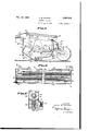
- Fig. 1 is a side elevation of a carrier scraper embodying my invention with the main and auxiliary bowls in a carrying or loaded position,
- Fig. 2 is a vertical longitudinal section of the device of Fig. 1 with the main and auxiliary bowls in discharge position.
- Fig. 3 is a vertical longitudinal section of the device of Fig. 1 showing the bowls in scraping position
- Fig. 4 is a longitudinal sectional View along the line 4-4 of Fig. 1, and
- Fig. 5 is a section along the line 5-5 of Fig. 4.
- I0 denotes the side frames Aof the scraper of conventional trussed beam conspaced cable I4, anchored at the end of the side frame 55 and suitably journaled in the side skirts I9.
- the scraper includes side plates I8 rigidly secured to the side frames I0 to define the sides of the compartment into which the earth is gathered by the scraper means, which side plates in this instance extend below the side frames ID t0 provide a skirt I9.
- the main bowl 2D as usual, is a scoop shaped body, which in the loading vand carrying operations forms the bottom and back of the earthcompartment, and is connected for pivotal movement at its forward end to a pin 2I extendingtransversely between A post 22 disposed medially of the back of the main bowl 20 extends upwardly therefrom 1n the form of a gooseneck 23.
- the main bowl 20 is rendered tiltable on its pivot 2I bymeans of its operative connection to a pull cable 2'I passing through a plurality of sheaves 28 and 29, the former being carried at the outer end of gooseneck 23 and the latter being positioned on a beam 30 spanning a pair of posts 3I extending upwardly from the side frames I0 at the forward end of scraper.
- the posts 3l are braced by the rearwardly declining struts connected at their opposite ends to a pair oi' shorter posts 33 extending upwardly from frame I0 midway the sides of the scraper.
- Fig. 1 one end of the pull cable 2I is anchored on the conventional block for sheaves 29.
- the opposite end extends to a suitable power drum on the tractor (not shown).
- pull exerted on cable 21 will tend to shorten the distance between sheaves 28 and 29 and thus tilt main bowl 20 on its pivot 2l to effect discharge of the contents of the scraper, Whereas slacking oi on the cable 21 will permit bowl 20 to return to its scraping position, such return being aided and insured by certain novel means presently to be described.
- a scraper blade 35 having a rigid support 36 extends transversely between the skirts I9 with its cutting edge projecting slightly below the edge of the said skirts. If desired the parallel pin 2l may be additionally journaled on the blade support 36 for additional strength in the structure.
- the blade may be provided with an adjustable connection to the support 35 to meet varying conditions.
- An auxiliary bowl or front apron 40 is supported for relative pivotal movement with respect to the main bowl by a pair of rigidly connected rearwardly projecting arms 4
- the auxiliary bowl 45 is automatically moved from a closed position, in which its lowermost edge abuts the blade 35 (see Fig. l) to its full open or raised position (see Fig. 2) upon the tilting of the main bowl 20.
- ] include links 44 connected at one end to the auxiliary bowl 45 and having an operative connection with pusher rods 45 slidably disposed on the side members of frame
- Blocks 48 on the rearmost ends of pusher rods 45 carry sheaves 49 through which cable 5l] is passed to provide an operative connection whereby pull exerted on the cable 55 will cause the pusher rods 45 to be moved forwardly to urge auxiliary bowl upwardly about its pivots 42 into its opened position.
- the two ends of cable 50 are anchored, as at 5
- the housing 54 there are two longitudinally extending superimposed compression springs 55 the function of which, through the medium of operative connections with cable 5U, is to urge the main bowl 20 rearwardly from its full open position (see Fig. 2) past its center of gravity toward its scraping position (see Fig. 3)
- Opposite ends of the springs 55 are anchored to the end walls of the housing 54, as at 5
- cable 50 is looped about sheaves 54 on blocks 53, passing out of the spring box 54 over sheaves 55 and 65 positioned at opposite ends of the housing 54.
- Dogs 61 normally urged into engagement with blocks 53 by springs 14, are likewise provided with an inclined surface 15 against which the upward thrust Vof wedge pins 13 will be transmitted into lateral movement of the dogs 51 out of engagement with sheave blocks 63 compressing springs 14.
- dogs 51 When dogs 51 are thus retracted further pull on cable 55, as main bowl 20 moves toward its dumping position, will draw the sheave blocks toward each other and compress the springs 6D for the purpose above stated.
- Actuation of the triggers 59 draws rods 1
- Continued movement of the l'main bowl 20 toward full discharge position draws on cable 50 which in passing over sheaves 64 in the spring box 54 compresses the springs 5B.
- cable 21 is slacked off at the power drum and the tension Vof springs 5U transmitted through cable 50 rwill pull mainv bowl 20 past its center of gravity from whence of its own weight it will return toward its lowermost or loading position.
- and resetting of triggers 59 is effected by any yieldable means such asv springs 11 connected between the outer ends of the rods 1
- the simplified means for automatically actuating the auxiliary bowl and insuring return of the main bowl to its loading position will be found advantageous in that they permit economies in cost of construction and maintenance, while at the same time attaining obvious efficiencies in operation.
- a carrier scraper of the type wherein oppositely arranged main and auxiliary bowls are supported by a frame for tilting movement relative to each other from carrying to discharge position comprising means for effecting tilting of the main bowl, members slidably mounted on said frame having operative connections with the auxiliary bowl to cause it to be moved from carrying to discharge position, and means actuated by the main bowl upon tilting thereof to eilect movement of the slidable members.
- a carrier scraper of the type wherein oppositely arranged main and auxiliary bowls are supported by a frame for tilting movement relative to each other from carrying to discharge position comprising means for effecting tilting of the main bowl, members slidably mounted on said frame having operative connections with the auxiliary bowl to cause it to be moved from carrying to discharge position, means actuated by the main bowl upon tilting thereof to effect movement of the slidable members, and stop means for the slidable members.
- a carrier scraper of the type wherein oppositely arranged main and auxiliary bowls are supported by a frame for tilting movement relative to each other from carrying to discharge position comprising means for eiecting tilting of the main bowl, members slidably mounted on said frame, supports therefor, means actuated by the main bowl upon tilting thereof to eiect movement of the slidable members, means connecting the slidable members with the auxiliary bowl ⁇ to cause it to be moved from carrying to discharge position at a rate greater than that of the concomitant movement of the main bowl, and stop means for the slidable members.
- a carrier scraper of the type wherein oppositely arranged main and auxiliary bowls are supported by a frame for tilting movement relative to each other from carrying to discharge position comprising means for effecting tilting of the main bowl, members slidably mounted on said frame, links connecting the slidable members and the auxiliary bowl, and means actuated by the main bowl upon the tilting thereof to effect movement of the slidable members.
- a carrier scraper of the type wherein oppositely arranged main and auxiliary bowls are supported by a frame for tilting movement relative to each other from carrying to discharge position comprising means for eiecting tilting of the main bowl, members slidably mounted on said frame, pusher rods xed on the slidable members, links connecting the pusher rods and the auxiliary bowl, and means actuated by the main bowl upon tilting thereof to eiect movement of the slidable members.
- main and auxiliary bowls are supported by a frame for tilting movement relative to each other from carrying ⁇ to discharge position
- a frame for tilting movement relative to each other from carrying ⁇ to discharge position
- means for tilting the main bowl a pair of members slidably mounted on said frame, means connecting the slidable members and the auxiliary bowl to effect tilting of the latter upon movement of the former, and flexible means having an operative connection with the main bowl and said slidable members to actuate the slidable members upon the tilting of the main bowl.
- a carrier scraper of the type wherein oppositely arranged main and auxiliary bowls are supported by a frame for tilting movement relative to each other from carrying to discharge position comprising means for tilting the main bowl, a pair of members slidably mounted on said frame, means connecting the slidable members and the auxiliary bowl to effect tilting of the latter upon movement of the former, flexible means having an operative connection with the main bowl and said slidable members to actuate the slidable members upon the tilting of the main bowl, and stop means limiting the movement of the slidable members.
- a carrier scraper of the type wherein oppositely arranged main and auxiliary bowls are supported by a frame for tilting movement relative to each other from carrying to discharge position comprising means for tilting the main bowl, a pair of members slidably mounted on said frame, means connecting the slidable members and the auxiliary bowl to effect tilting of the latter upon movement of the former, flexible means having an operative connection with the main bowl and said slidable members to actuate the slidable members upon the tilting of the main bowl and yieldable means releasable upon movement of the slidable members a predetermined distance to urge the main bowl from its tilted position back toward its carrying position.
- a carrier scraper of the type wherein oppositely arranged main and auxiliary bowls are supported by a frame for tilting movement relative to each other from carrying to discharge position comprising means for tilting the main bowl, a pair of memb-ers slidably mounted on said frame, means connecting the slidable mem-bers and the lauxiliary bowl to effect tilting of the latter upon movement of the former, flexible means having an operative connection with the main bowl and said slidable members to actuate the slidable members upon the tilting of the main bowl, compressible members having an operative connection with the said flexible means effective upon compression to urge the main fowl from its tilted position back toward its carrying position, and releasable means normally restraining the compressible members.
- a carrier scraper of the type wherein oppositely arranged main and auxiliary bowls are supported by a frame for ltilting movementrelative to each other from carrying to discharge position comprising means for tilting the main bowl, a pair of members slidably mounted on said frame, means connecting the slidable members and the auxiliary bowl to effect tilting of the latter upon movementwof the former, flexible means having an operative connection with the main bowl and said slidable members to actuate the slidable members upon the tilting of the main bowl, compressble members having an operative connection with the said iiexible means effective upon compression to urge the main bowl from its tilted position back toward its carrying position, releasable means restraining the compressible members, and means actuated by the slidable members to effect release of the restraining means f-or the compressible members.
- a carrier scraper of the type wherein oppositely arranged main and auxiliary bowls are supported by a frame for tilting movement relative to each other from carrying to discharge position comprising means for tiling the main bowl, a pair of members slidably mounted on said frame, means connecting the slidable members and the auxiliary bowl to effect tilting of the latter upon movement of the former, flexible means having an operative connection with the main bowl and said slidable members to actuate the slidable members upon the tilting of the main bowl, compressble members having an Ioperative connection with the said flexible means eiiective upon compression to urge the main lbowl from its tilted position back toward its carrying position, releasable dogs normally restraining the compressible members, trigger means in the path of the slidable members having lan operative connection to release said dogs.
- a carrier scraper of the type wherein oppositely arranged main and auxiliary bowls are supported for tilting movement relative to each other from carrying to discharge position comprising means for tilting the main bowl, compressible members having an operative connection with the main bowly effective upon compression to urge the main bowl' from its tilted position back toward its carrying position, and releasable means restraining the compressi'ble members through the greater portion of the tilting movement of the main bowl from its carrying to discharge position.
Description
NGV. 10, 1942. 1 w ZAHARA 2,301,604
CARRIER S CRAPER Filed June 24, 1941 2 Sheets-Sheet 1 v f To. JoH/v W ZAHAQA ATTORNEYS.
NOV. l0, 1942. J, w, ZAHARA 2,301,604
CARR IER S QRAPER Filed June 24, 1941 2 Sheets-Sheet 2 INVENTOR. JOHN W ZAHAEA l "www A TTORNE'YS.
Patented Nov. 10, 1942 UNITED STATES PATENT OFFICE 2,301,604 CARRIER SCRAPER John W. Zahara, San Carlos, Calif.
Application June 24, 1941, Serial No. 399,487,`
13 Claims.
The present invention relates to carrier scrapers of the heavy duty road grader type employed in construction work of all kinds wherein movement of earth is desired. More specifically my invention relates to earth movers utilizing main and auxiliary bowls.
One of the principal objects of the invention is the improvement and simplification of the means employed to move relatively the main and auxiliary bowls in the loading and dumping' operations.
'I'he invention also relates to improvements in means for insuring the return of the main bowl from its discharge to loading position.
Additionally, the invention forming the subject-matter of this application contemplates certain novelties in construction whereby the means for actuating the auxiliary bowl, or apron as it is termed by some in the art, are so positioned as to reduce wear and tear thereon to a minimum and to thus eiiect certain desirable economies in the operation of the devices.
Other objects and advantages will become apparent as this specication proceeds and the novelty of the invention will be set forth in the appended claims.
In the drawings forming a part thereof:
Fig. 1 is a side elevation of a carrier scraper embodying my invention with the main and auxiliary bowls in a carrying or loaded position,
Fig. 2 is a vertical longitudinal section of the device of Fig. 1 with the main and auxiliary bowls in discharge position.
Fig. 3 is a vertical longitudinal section of the device of Fig. 1 showing the bowls in scraping position,
Fig. 4 is a longitudinal sectional View along the line 4-4 of Fig. 1, and
Fig. 5 is a section along the line 5-5 of Fig. 4.
'Ihe preferred embodiment of my invention il-` lustrated in the drawings includes the essential elements of a carrier scraper of a well-known type. I'he numeral I0 denotes the side frames Aof the scraper of conventional trussed beam conspaced cable I4, anchored at the end of the side frame 55 and suitably journaled in the side skirts I9.
as at I5, passing over a sheave I6 disposed on the beams I2 and taken up by a conventional power drum on the tractor by which the scraper is drawn (not shown). Thus the forward end of the scraper is not only supported by the combination of the beam I2 and the cable I4, but
by these means may be raised and lowered between scraping an-d carrying positions (see Figs. 3 and l, respectively).
Additionally, the scraper includes side plates I8 rigidly secured to the side frames I0 to define the sides of the compartment into which the earth is gathered by the scraper means, which side plates in this instance extend below the side frames ID t0 provide a skirt I9. The main bowl 2D, as usual, is a scoop shaped body, which in the loading vand carrying operations forms the bottom and back of the earthcompartment, and is connected for pivotal movement at its forward end to a pin 2I extendingtransversely between A post 22 disposed medially of the back of the main bowl 20 extends upwardly therefrom 1n the form of a gooseneck 23.
The main bowl 20 is rendered tiltable on its pivot 2I bymeans of its operative connection to a pull cable 2'I passing through a plurality of sheaves 28 and 29, the former being carried at the outer end of gooseneck 23 and the latter being positioned on a beam 30 spanning a pair of posts 3I extending upwardly from the side frames I0 at the forward end of scraper. The posts 3l are braced by the rearwardly declining struts connected at their opposite ends to a pair oi' shorter posts 33 extending upwardly from frame I0 midway the sides of the scraper.
As will be noted from Fig. 1 one end of the pull cable 2I is anchored on the conventional block for sheaves 29. The opposite end extends to a suitable power drum on the tractor (not shown). It will therefore be apparent that pull exerted on cable 21 will tend to shorten the distance between sheaves 28 and 29 and thus tilt main bowl 20 on its pivot 2l to effect discharge of the contents of the scraper, Whereas slacking oi on the cable 21 will permit bowl 20 to return to its scraping position, such return being aided and insured by certain novel means presently to be described.
A scraper blade 35 having a rigid support 36 extends transversely between the skirts I9 with its cutting edge projecting slightly below the edge of the said skirts. If desired the parallel pin 2l may be additionally journaled on the blade support 36 for additional strength in the structure.
It will be readily appreciated that the blade may be provided with an adjustable connection to the support 35 to meet varying conditions.
An auxiliary bowl or front apron 40 is supported for relative pivotal movement with respect to the main bowl by a pair of rigidly connected rearwardly projecting arms 4|, the ends of which are connected to trunnions 42 in lugs 43 on the posts 33.
The auxiliary bowl 45 is automatically moved from a closed position, in which its lowermost edge abuts the blade 35 (see Fig. l) to its full open or raised position (see Fig. 2) upon the tilting of the main bowl 20. The means for effecting this automatic opening and closing of the auxiliary bowl 4|] include links 44 connected at one end to the auxiliary bowl 45 and having an operative connection with pusher rods 45 slidably disposed on the side members of frame ||l and extending through the posts 33. Blocks 48 on the rearmost ends of pusher rods 45 carry sheaves 49 through which cable 5l] is passed to provide an operative connection whereby pull exerted on the cable 55 will cause the pusher rods 45 to be moved forwardly to urge auxiliary bowl upwardly about its pivots 42 into its opened position. Y
The two ends of cable 50 are anchored, as at 5|, on post 22 on main bowl 20, from whence cable 55 extends through sheaves 52 in blocks 53 located on the top 'and either end of the cornpression spring housing 54 at the rear of the scraper. From sheaves 52 cable 50 extends through sheaves 55 in blocks 55 on the side frames l5 adjacent posts 33 and from thence over sheaves 45 back to sheaves 51 in blocks 53 and into the compression spring box 54 (see Fig. 4). By multiplying the number of sheaves 49 and 51 the speed of movement of auxiliary bowl 4|] may be decreased for heavy duty operations.
Within the housing 54 there are two longitudinally extending superimposed compression springs 55 the function of which, through the medium of operative connections with cable 5U, is to urge the main bowl 20 rearwardly from its full open position (see Fig. 2) past its center of gravity toward its scraping position (see Fig. 3) Opposite ends of the springs 55 are anchored to the end walls of the housing 54, as at 5|, and their free ends receive keeper pins 52 projecting from sheave blocks 53. As will be noted from Fig. 4 cable 50 is looped about sheaves 54 on blocks 53, passing out of the spring box 54 over sheaves 55 and 65 positioned at opposite ends of the housing 54.
Normally blocks 53 are locked against longitudinal movement in the housing 54, and hence springs 50 are retained against compression, by dogs 51 the tips of which engage the projecting lips 68 on blocks 53. Release of the dogs 51 is effected when blocks 48, under the pull of cable 55 on sheaves 49, are moved forwardly to strike the triggers 59 slidably supported on stops 10 on frame I5. Movement of triggers 59 causes rods 1|, with which they are connected, to be drawn forwardly moving the inclined surfaces 12, at the opposite ends of the rods 1|, under and urging upwardly the wedge pins 13. Wedge pins 13 are slidably retained by any suitable guide means, such as straps (not shown). Dogs 61, normally urged into engagement with blocks 53 by springs 14, are likewise provided with an inclined surface 15 against which the upward thrust Vof wedge pins 13 will be transmitted into lateral movement of the dogs 51 out of engagement with sheave blocks 63 compressing springs 14. When dogs 51 are thus retracted further pull on cable 55, as main bowl 20 moves toward its dumping position, will draw the sheave blocks toward each other and compress the springs 6D for the purpose above stated.
While in the preferred form of the invention I have illustrated a wedge type dog release it will be readily appreciated by those skilled in the art that other means may be substituted with equal eiiicacy. There are many ways in which triggers 69 and dogs 51 may be linked for conjoint movement.
Operation To set the machine for the loading operation, i. e., scraping, the operator takes up cable 21 on the tractor power drum to raise the main bowl 20 suiiiciently to cause a pull on cable 50. Since both ends of cable 50 are anchored on post 22 this initial movement will draw sheave blocks 48 toward the stops 10 and urge pusher rods 45 forwardly which, through the links 4|, will swing auxiliary bowl 4|] about its pivot 42. This movement of auxiliary bowl 45 need be very slight since only a, relatively narrow slot or opening between its bottom edge and blade 35 is necessary to eifectively load the scraper (see Fig. 3). In practice the earth passing over blade 35 under the momentum of the vehicle coming from the bottom surges within the compartment to ll both main and auxiliary bowls.
When the scraper is fully loaded the operator takes up cable |4 on the power drum at the tractor to raise the carrier clear ofthe earth line, at the same time slacking oir on cable 21 to permit the weight of the load to lower the main bowl 20 to its carrying position and move the auxiliary bowl 40 into its closed position abutting the Vblade 35 (see Fig. 1).
` In the dumping operation the operator is required to merely take up on cable 21 until the main bowl is raised to its full discharge position (see Fig. 2) as the opening of the auxiliary bowl 4|) is fully automatic. As main bowl 20 swings upwardly about its pivot 2| cable 55, anchored on post 22, is drawn over sheaves 52, 55, 49 and 51, causing sheave block 48 and pusher rod 45 to slide forwardly and by means of the link 44 urge auxiliary bowl 4|) about its pivotal connection 42 to post 33 into full discharge position (see. Fig. 2). Blocks 48 at the end of their paths oi travel actuate triggers 63 and are checked by stops 10 on the side frame l0, thus limiting further opening of the auxiliary bowl 4|).
Actuation of the triggers 59 draws rods 1|' forwardly to thrust wedge pins 13 upwardly to disengage the dogs 51 and thus release the sheave blocks 53. Continued movement of the l'main bowl 20 toward full discharge position draws on cable 50 which in passing over sheaves 64 in the spring box 54 compresses the springs 5B. When the load has been discharged cable 21 is slacked off at the power drum and the tension Vof springs 5U transmitted through cable 50 rwill pull mainv bowl 20 past its center of gravity from whence of its own weight it will return toward its lowermost or loading position. Return of rods 1| and resetting of triggers 59 is effected by any yieldable means such asv springs 11 connected between the outer ends of the rods 1|) and the vehicle frame. i
It win be apparent to those skilled in the are hereof provision has been made for minimizing wear and tear on cables and sheaves and other means for actuating the auxiliary bowl by locating `the same away from forward end of the machine at which earth is contacted.
Additionally, the simplified means for automatically actuating the auxiliary bowl and insuring return of the main bowl to its loading position will be found advantageous in that they permit economies in cost of construction and maintenance, while at the same time attaining obvious efficiencies in operation.
Having fully shown land described a preferred embodiment of my invention for purposes of illustration I desire full protection as to the many permissible changes therein which may be made within the scope of the appended claims.
The invention claimed is:
1. A carrier scraper of the type wherein oppositely arranged main and auxiliary bowls are supported by a frame for tilting movement relative to each other from carrying to discharge position comprising means for effecting tilting of the main bowl, members slidably mounted on said frame having operative connections with the auxiliary bowl to cause it to be moved from carrying to discharge position, and means actuated by the main bowl upon tilting thereof to eilect movement of the slidable members.
2. A carrier scraper of the type wherein oppositely arranged main and auxiliary bowls are supported by a frame for tilting movement relative to each other from carrying to discharge position comprising means for effecting tilting of the main bowl, members slidably mounted on said frame having operative connections with the auxiliary bowl to cause it to be moved from carrying to discharge position, means actuated by the main bowl upon tilting thereof to effect movement of the slidable members, and stop means for the slidable members.
3. A carrier scraper of the type wherein oppositely arranged main and auxiliary bowls are supported by a frame for tilting movement relative to each other from carrying to discharge position comprising means for eiecting tilting of the main bowl, members slidably mounted on said frame, supports therefor, means actuated by the main bowl upon tilting thereof to eiect movement of the slidable members, means connecting the slidable members with the auxiliary bowl `to cause it to be moved from carrying to discharge position at a rate greater than that of the concomitant movement of the main bowl, and stop means for the slidable members.
4. A carrier scraper of the type wherein oppositely arranged main and auxiliary bowls are supported by a frame for tilting movement relative to each other from carrying to discharge position comprising means for effecting tilting of the main bowl, members slidably mounted on said frame, links connecting the slidable members and the auxiliary bowl, and means actuated by the main bowl upon the tilting thereof to effect movement of the slidable members.
5. A carrier scraper of the type wherein oppositely arranged main and auxiliary bowls are supported by a frame for tilting movement relative to each other from carrying to discharge position comprising means for eiecting tilting of the main bowl, members slidably mounted on said frame, pusher rods xed on the slidable members, links connecting the pusher rods and the auxiliary bowl, and means actuated by the main bowl upon tilting thereof to eiect movement of the slidable members.
' sitely arranged main and auxiliary bowls are supported by a frame for tilting movement relative to each other from carrying `to discharge position comprising means for tilting the main bowl, a pair of members slidably mounted on said frame, means connecting the slidable members and the auxiliary bowl to effect tilting of the latter upon movement of the former, and flexible means having an operative connection with the main bowl and said slidable members to actuate the slidable members upon the tilting of the main bowl.
8. A carrier scraper of the type wherein oppositely arranged main and auxiliary bowls are supported by a frame for tilting movement relative to each other from carrying to discharge position comprising means for tilting the main bowl, a pair of members slidably mounted on said frame, means connecting the slidable members and the auxiliary bowl to effect tilting of the latter upon movement of the former, flexible means having an operative connection with the main bowl and said slidable members to actuate the slidable members upon the tilting of the main bowl, and stop means limiting the movement of the slidable members.
9. A carrier scraper of the type wherein oppositely arranged main and auxiliary bowls are supported by a frame for tilting movement relative to each other from carrying to discharge position comprising means for tilting the main bowl, a pair of members slidably mounted on said frame, means connecting the slidable members and the auxiliary bowl to effect tilting of the latter upon movement of the former, flexible means having an operative connection with the main bowl and said slidable members to actuate the slidable members upon the tilting of the main bowl and yieldable means releasable upon movement of the slidable members a predetermined distance to urge the main bowl from its tilted position back toward its carrying position.
10. A carrier scraper of the type wherein oppositely arranged main and auxiliary bowls are supported by a frame for tilting movement relative to each other from carrying to discharge position comprising means for tilting the main bowl, a pair of memb-ers slidably mounted on said frame, means connecting the slidable mem-bers and the lauxiliary bowl to effect tilting of the latter upon movement of the former, flexible means having an operative connection with the main bowl and said slidable members to actuate the slidable members upon the tilting of the main bowl, compressible members having an operative connection with the said flexible means effective upon compression to urge the main fowl from its tilted position back toward its carrying position, and releasable means normally restraining the compressible members.
11. A carrier scraper of the type wherein oppositely arranged main and auxiliary bowls are supported by a frame for ltilting movementrelative to each other from carrying to discharge position comprising means for tilting the main bowl, a pair of members slidably mounted on said frame, means connecting the slidable members and the auxiliary bowl to effect tilting of the latter upon movementwof the former, flexible means having an operative connection with the main bowl and said slidable members to actuate the slidable members upon the tilting of the main bowl, compressble members having an operative connection with the said iiexible means effective upon compression to urge the main bowl from its tilted position back toward its carrying position, releasable means restraining the compressible members, and means actuated by the slidable members to effect release of the restraining means f-or the compressible members.
l2. A carrier scraper of the type wherein oppositely arranged main and auxiliary bowls are supported by a frame for tilting movement relative to each other from carrying to discharge position comprising means for tiling the main bowl, a pair of members slidably mounted on said frame, means connecting the slidable members and the auxiliary bowl to effect tilting of the latter upon movement of the former, flexible means having an operative connection with the main bowl and said slidable members to actuate the slidable members upon the tilting of the main bowl, compressble members having an Ioperative connection with the said flexible means eiiective upon compression to urge the main lbowl from its tilted position back toward its carrying position, releasable dogs normally restraining the compressible members, trigger means in the path of the slidable members having lan operative connection to release said dogs.
13. A carrier scraper of the type wherein oppositely arranged main and auxiliary bowls are supported for tilting movement relative to each other from carrying to discharge position comprising means for tilting the main bowl, compressible members having an operative connection with the main bowly effective upon compression to urge the main bowl' from its tilted position back toward its carrying position, and releasable means restraining the compressi'ble members through the greater portion of the tilting movement of the main bowl from its carrying to discharge position.
JOHN W. ZAHARA.
Priority Applications (1)
| Application Number | Priority Date | Filing Date | Title |
|---|---|---|---|
| US399487A US2301604A (en) | 1941-06-24 | 1941-06-24 | Carrier scraper |
Applications Claiming Priority (1)
| Application Number | Priority Date | Filing Date | Title |
|---|---|---|---|
| US399487A US2301604A (en) | 1941-06-24 | 1941-06-24 | Carrier scraper |
Publications (1)
| Publication Number | Publication Date |
|---|---|
| US2301604A true US2301604A (en) | 1942-11-10 |
Family
ID=23579706
Family Applications (1)
| Application Number | Title | Priority Date | Filing Date |
|---|---|---|---|
| US399487A Expired - Lifetime US2301604A (en) | 1941-06-24 | 1941-06-24 | Carrier scraper |
Country Status (1)
| Country | Link |
|---|---|
| US (1) | US2301604A (en) |
Cited By (2)
| Publication number | Priority date | Publication date | Assignee | Title |
|---|---|---|---|---|
| US2508421A (en) * | 1947-04-03 | 1950-05-23 | Bucyrus Erie Co | Dumping control for scrapers |
| US2697292A (en) * | 1948-12-10 | 1954-12-21 | Terrence Rich Res | Digging adjustment for roll-over scrapers |
-
1941
- 1941-06-24 US US399487A patent/US2301604A/en not_active Expired - Lifetime
Cited By (2)
| Publication number | Priority date | Publication date | Assignee | Title |
|---|---|---|---|---|
| US2508421A (en) * | 1947-04-03 | 1950-05-23 | Bucyrus Erie Co | Dumping control for scrapers |
| US2697292A (en) * | 1948-12-10 | 1954-12-21 | Terrence Rich Res | Digging adjustment for roll-over scrapers |
Similar Documents
| Publication | Publication Date | Title |
|---|---|---|
| US2650440A (en) | Bowl ejecting mechanism for carry-type scrapers | |
| US2301604A (en) | Carrier scraper | |
| US2305481A (en) | Scraper | |
| US2773320A (en) | Digging and carrying scraper | |
| US2083307A (en) | Grading machine | |
| US2304786A (en) | Scraper | |
| US2425601A (en) | Scraping apparatus | |
| US2216235A (en) | Scraper | |
| US2112105A (en) | Telescoping scraper | |
| US1963665A (en) | Scraper | |
| US2127223A (en) | Carrying scraper | |
| US3574961A (en) | Automatic loading and unloading device | |
| US3334428A (en) | Material handling apparatus | |
| US2078500A (en) | Road scraper | |
| US2262283A (en) | Scraper | |
| US2159045A (en) | Wheeled scraper | |
| US2387263A (en) | Wheeled scraper | |
| US3308565A (en) | Protective shield on earth-carrying scraper | |
| US3584403A (en) | Self-loading scraper having ejector which moves rearwardly for unloading | |
| US2567118A (en) | Apron and ejector control for carry-type scrapers | |
| US1453540A (en) | Bucket | |
| US2669043A (en) | Dumping control for scrapers | |
| US2722065A (en) | Mold board for earthmoving scraper | |
| US2363225A (en) | Load carrying scraper | |
| US2321410A (en) | Scraper |