US2286355A - Centrifugal separator - Google Patents
Centrifugal separator Download PDFInfo
- Publication number
- US2286355A US2286355A US388749A US38874941A US2286355A US 2286355 A US2286355 A US 2286355A US 388749 A US388749 A US 388749A US 38874941 A US38874941 A US 38874941A US 2286355 A US2286355 A US 2286355A
- Authority
- US
- United States
- Prior art keywords
- rotor
- valve
- centrifugal
- liquid
- motor
- Prior art date
- Legal status (The legal status is an assumption and is not a legal conclusion. Google has not performed a legal analysis and makes no representation as to the accuracy of the status listed.)
- Expired - Lifetime
Links
- 239000007788 liquid Substances 0.000 description 31
- 238000007789 sealing Methods 0.000 description 29
- 239000012530 fluid Substances 0.000 description 21
- 239000007787 solid Substances 0.000 description 16
- 239000000463 material Substances 0.000 description 4
- 239000010802 sludge Substances 0.000 description 4
- 238000009825 accumulation Methods 0.000 description 3
- 230000000694 effects Effects 0.000 description 3
- 239000002184 metal Substances 0.000 description 3
- 239000000203 mixture Substances 0.000 description 3
- 230000002093 peripheral effect Effects 0.000 description 3
- 238000013461 design Methods 0.000 description 2
- 238000000926 separation method Methods 0.000 description 2
- 238000013459 approach Methods 0.000 description 1
- 238000004891 communication Methods 0.000 description 1
- 230000002706 hydrostatic effect Effects 0.000 description 1
- 238000000034 method Methods 0.000 description 1
- 238000012986 modification Methods 0.000 description 1
- 230000004048 modification Effects 0.000 description 1
- 230000000717 retained effect Effects 0.000 description 1
Images


Classifications
-
- B—PERFORMING OPERATIONS; TRANSPORTING
- B04—CENTRIFUGAL APPARATUS OR MACHINES FOR CARRYING-OUT PHYSICAL OR CHEMICAL PROCESSES
- B04B—CENTRIFUGES
- B04B1/00—Centrifuges with rotary bowls provided with solid jackets for separating predominantly liquid mixtures with or without solid particles
- B04B1/10—Centrifuges with rotary bowls provided with solid jackets for separating predominantly liquid mixtures with or without solid particles with discharging outlets in the plane of the maximum diameter of the bowl
- B04B1/14—Centrifuges with rotary bowls provided with solid jackets for separating predominantly liquid mixtures with or without solid particles with discharging outlets in the plane of the maximum diameter of the bowl with periodical discharge
- B04B1/16—Centrifuges with rotary bowls provided with solid jackets for separating predominantly liquid mixtures with or without solid particles with discharging outlets in the plane of the maximum diameter of the bowl with periodical discharge with discharging outlets controlled by the rotational speed of the bowl
- B04B1/18—Centrifuges with rotary bowls provided with solid jackets for separating predominantly liquid mixtures with or without solid particles with discharging outlets in the plane of the maximum diameter of the bowl with periodical discharge with discharging outlets controlled by the rotational speed of the bowl controlled by the centrifugal force of an auxiliary liquid
Definitions
- the present invention pertains to the art of centrifugal separators designed to effect separation of solids from a liquid, or separation of solids from a mixture of liquids.- It pertains lto the type of centrifugal in which s olids are intermittently discharged through valve-controlled discharge passages in the wall of the centrifugal rotor, such as described in my prior application, Serial No. 318,672, led February 13, 1940, for Centrifugal separator.
- valves are operated by fluid pressure motors to disrial fed to the mainbody of the rotor through the openings I8 passes upwardly through ⁇ the openings I1 intothe space between the stratifycharge the accumulated sludge periodically.
- a feature of the present invention consists in the fact that it embodies an arrangement which is an improvement over that of my prior application, No. 318,672, in these particulars.
- the invention includes a sealing connection in which the sealing is enhanced by the eifect'of centrifugal force in the rotation of the rotor.
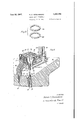
- Figure l is la central axial section through the left-hand side of a centrifugal rotor of 'the in- Figure 2 is a detailed sectional view, partly diagramatic, illustrating a cross-section through a motor of one embodiment of the invention
- FIG. 3 is a perspective view, illustrating the method of mounting the sealing rings of the motor of Figure 2
- Figure 4 is a view similar to Figure 2, illustrating an'alternative form of the invention.
- the machine of the invention is similar ln most particulars'to that'of my prior application ing discs.
- the lighter liquid passes inwardly through the spaces between the superposed discs I8 into a space 23 within the discs, and upwardly through the space 24 between a tubular extension 25 of the dividing wall, and feed tube I5.
- the liquid centrifugal eiiluents discharged over ring dam 22 Aand from tube 25 are collected in separate centrifugal covers, as will be understood by those skilled in the art.
- the inner peripheral wall of the main body of the rotor consists of opposed frusto-conical surfaces 26 and 21, and the point of maximum diameter of the main body of the rotor is located approximately centrally of this portion of the rotor.
- AI5 and sleeve I2 and through openings I6 in the lower end vof the tube I5 into-the zone 'of the main body of the rotor occupied by registering openings I'I in the stratifying discs I8. Matewill be deposited along the surfaces 26 and 21 and flow outwardly along these surfaces to the zone 28, while the liquids are separated and sepabove.
- the rotor is provided with a plurality of small passages 29 through which these solids are intermittently discharged. These passages may be provided with bushings 30, radially extending valve guide members 3
- a reciprocating valve 33 is provided for co-action with each of the valve seats 32, and each of these valves 33 is connected with a valve stem 34, which is actuated by means to be described hereinafter for intermittent discharge of -deposited solids through vthe valve seats 32 andbushings 30.
- Fluid pressure motors 35 operate to move the valves, anv individual motor being attached to each of the individual valve stems 34, and the Amotors being secured within-the rotor for rotation therewith.
- Each of these motors comprises a housing which consists of an end portion 36 This heavier constit- 2 l i 2,286,355 e v to effect sealing contact with the inner surface and a base portion 31 secured to the portion 36. This housing surrounds the moving parts of the motor.
- the base portion 31 has an annular extension 38 (see Fig'. 2) which lies adjacent the zone 28 of accumulation of solids.
- end 39 of the valve stem 34 has an inner end portion 4
- e 'Ihe housing base 31 is provided with a lateral extension 55 through which liquid is passed from the main body of lthe centrifugal rotor for actuating the fluid pressure motor.
- a bore 56 in extension 55 communicates'with ⁇ diagrammatic, in the interest ⁇ of simplicity of' illustration of the principles lof the invention.
- the inner endof conduit 49 is connected to a member 50, which has a bore (see, Fig. 2) communicating with the conduit 49', and also a channel 52 communicating with the inner end of bore 5
- a bore 53 extends outwardly from the .channel 52, and is connected to a second, ⁇ and smaller, conduit 54, which extends outwardly from the member 50 to a connection with a bore 51 in the lateral extension 55 of the housing base 31.
- the bore 51 communicates with the space 58 between the end portion 36 of the housing and the outer surface of the movable member 4
- communicates with the sludge space 28 of the rotor, through the hollow interior of the member 59 of the motor, which is a stationary member having av cylindrical outer surface along which ⁇ the flange 42 of the movable member or piston 4
- the space 58 is also inv communication, through an orifice connecting this space with a bore 60 in an extension. 6
- the most impotrant feature of the invention consists in the provision of motor sealing devices designed to function in such a way that the centrifugal force ⁇ due to rotation of the rotor exerts a sealing effect on the sealing members.
- the stationary member or cylinder 59 is provided with flanges 63 and 64, and split metal sealing rings 65 and 66 are confined between these flanges, 'with their outer surfaces contacting the inner surface of the 'flange 42 of the movable member or piston 4
- the splits in the rings are dsaligned in order to prevent leakage between them, being preferably spaced apart in the assembly of the rings with the motor, as illustrated in Figure 3 of the drawings.
- the rings 65 and 66 perform their sealing function under the influence of centrifu-- gal force, thereby effectively preventing leakage through the space between the relatively moving parts of the fluid pressure motor.
- FIG 4 An alternative form of the invention is illustrated in Figure 4.
- This form of the invention is similar to that of Figures 2 and 3 with respect to general assembly and hydraulic connections, but it involves a different type of sealing connection.
- a single ring 10 of rubber or similar elastically deformable material is mounted between the'stationary flanges 63 and 64 in the motor of Figure 4.
- centrifugal force acts upon the ring 10 both to force it in tight sealing relation to flange 63 and to expand it laterally to force it into liquid-tight sealing relation with piston 4
- a centrifugal separator comprising a centrifugal rotor provided with a discharge outlet adapted to be alternately opened and closed to control the discharge of an effluent from said rotor, a valve adapted to be moved into discharge-permitting and discharge-preventing positions, respectively, with respect to said discharge outlet, a valve extension connected to said valve and extending inwardly into said centrifugal rotor and a fluid pressure motor within said rotor secured to saidrotor for rotation therewith and connected to said valve extension for operating the same, said fluid pressure motor including a member which is stationary with respect to said rotor and a member mounted for longitudinal movement relative to said stationary member in a direction .having a substantial radial component under the impelling force of fluid pressure, said stationary member having an abutment for supporting a sealing member, and a sealing member mounted between said relatively movable and stationary members of said motor l and adjacent said abutment at the inner side thereof, whereby the influence of centrifugal force generated by
- a centrifugal separator comprising a centrifugal rotor provided with a discharge outlet adapted to be alternately opened and closed to control the discharge of an eflluent from said rotor, a valve adapted to be moved into discharge-permitting and discharge-preventing positions, respectively, with respect to said discharge outlet, a valve extension connected to said valve andextending inwardly into said centrifurotor mounted on a substantially radial axis and secured to said rotor for rotation therewith and connected to said valve extension for operating the same, said fluid pressure motor including a member which is stationary with respect to said rotor and a member mounted for longitudinal movement relative to said stationary member in a direction having a substantial radial component under the impelling force of fluid pressure, said stationary member having an abutment for supporting a sealing member, and a sealing member mounted between said relatively movable and stationary members of said motor and adjacent said abutment at the inner side thereof, whereby the infiuence of centrifugal force generated by
- a centrifugal separator comprising a centrifugal rotor provided with a discharge outlet adapted to be alternately opened and closed to control the dischargeof an effluent from said rotor, a valve adapted to be moved into discharge-permitting and discharge-v preventing positions, respectively, with respect to said discharge outlet, a valve extension connected to said valve and extending inwardly into said centrifugal rotor and Ia fluid pressure motor within said rotor secured to said rotor for rotation therewith and connected to said valve extension for operating the same, said fluid pressure motor including a member which is stationary with respect to said rotor and a member mounted for longitudinal movement relative to said stationary member in a direction having a substantial radial component under the impelling force of fluid pressure, said stationary member having an abutment for supporting a sealing member, and an elastically deformable sealing member mounted between said relativelymovable and stationary members of said motor and adjacent said abutment at the inner side thereof, whereby the infiuence of centri
- a centrifugal separator comprising a centrifugal rotor provided with a discharge outlet adapted to be alternately opened and closed to control the discharge of an effluent from said rotor, a valve adapted to be moved into discharge-permitting and discharge-preventing positions, respectively, with respect to said discharge outlet, a valve extension connected to said valve and extending inwardly into said centrifugal rotor and a fluid pressure motor within said rotor secured to said rotor for rotation therewith and connected to said valve extension for operating the same, said fluid pressure motor including a member which is stationary with respect to saidrotor and a member mounted for longitudinal movement relative to said stationary member in a direction having a substantial radial component under the impelling force of fluid pressure, said stationary member having an abutment for supporting a sealing member, and a rubber sealing member mounted between said relatively movable and stationary members of said motor and adjacent said abutment at the inner side thereof, whereby the influence of centrifugal force generated by rotation of the rotor,
- ya centrifugal separator comprising a centrifugal rotor provided with a discharge outlet adapted to be alternately opened gal rotor and a fiuid pressure motor within said" valve and extending inwardly into said centrifugal rotor and a fluid pressure motor Within said rotor secured to'said rotor for rotation therewithand connected to saidv valve extensiontfor operating the same, said ud pressure motor including a member which is stationary with respect to said rotor and a member mounted for ⁇ longitudinal movement relative to said stationary'member in a direction having a substantial radial component under the impelling force of fluid pressure, said stationary member having an abutment for supporting said sealing ring, and a metal sealing ring mounted between said relatively movable and stationary members of said motor and adjacent said abutment at the inner side thereof, whereby the influence of centrifugal force generated by rotation of the rotor forces said sealing ring into engagement with said abutment.
- a centrifugal separator comprising a centrifugal rotor provided with a discharge outlet adapted to be alternately opened and closed 'to control the discharge df an efuent from said rotor, a valve adapted to be'moved into discharge-permitting and discharge-preventing positions, respectively, with respect to said discharge outlet, a valve extension connected to said valve and extendingV inwardlyinto said centrifugal rotor and a iluid pressure motor within said rotor secured to said rotor for rotation therewith and connected to said valve extension for operatlng the same, said uid pressure motor including a member which is stationary with respect' to said rotor and a member mounted for longitudinal movement relative to said stationary member in a direction having a substantial radial commovable and stationary members of said mot'or;
Landscapes
- Centrifugal Separators (AREA)
Description
IJune 16, 1942. H, C, FlTzslMMONs 2,286,355
CENTRIFUGAL SEPARATOR Filed April 16, 1941 5 SheeLs-Sheefl 1 F/g'/ 25 I I Vl 1N VEN TOR I? 41M Haro/d C Hbf/771mm A TTORNE Y une l5, 3942s H. c. FITZSIMMONS 2,236,355
CENTRIFUGAL SEPARATOR Filed April 16, 1941 3 Sheets-Shee(l 2 A TTORN E Y June l, 1942. H, C, F|TZ$|MMQN5 2,286,355
CENTRIFUGAL SEPARATOR Filed April 16, 1941 3 Sheets-Sheet 5 INVENTOR Haro/d C 'nhnmons I Q1 01W/*4 y ATTORNEY vention,
Patented June 16, 1942 CENTRIFUGAL SEPARATOR Harold C. Fitzsimmons, West Chester, Pa., Vasslgnor to The Sharples Corporation, Philadelphia, Pa., a corporation of Delaware' AApplication April 16, 1941, Serial No. 388,743
I (Cl. 2334-20) 10 Claims.
The present invention pertains to the art of centrifugal separators designed to effect separation of solids from a liquid, or separation of solids from a mixture of liquids.- It pertains lto the type of centrifugal in which s olids are intermittently discharged through valve-controlled discharge passages in the wall of the centrifugal rotor, such as described in my prior application, Serial No. 318,672, led February 13, 1940, for Centrifugal separator.
i In the machine of that application, the valves are operated by fluid pressure motors to disrial fed to the mainbody of the rotor through the openings I8 passes upwardly through` the openings I1 intothe space between the stratifycharge the accumulated sludge periodically. In
the design of a centrifugal separator equipped with valves and motors of this kind, it is important that an arrangement be provided which is durable, delicately responsive in operation, and proof against leakage from the main body of the rotor through the motor parts. A feature of the present invention consists in the fact that it embodies an arrangement which is an improvement over that of my prior application, No. 318,672, in these particulars. A further feature is that the invention includes a sealing connection in which the sealing is enhanced by the eifect'of centrifugal force in the rotation of the rotor.
In the drawings,
Figure l is la central axial section through the left-hand side of a centrifugal rotor of 'the in- Figure 2 is a detailed sectional view, partly diagramatic, illustrating a cross-section through a motor of one embodiment of the invention,
` Figure 3 is a perspective view, illustrating the method of mounting the sealing rings of the motor of Figure 2, and
Figure 4 is a view similar to Figure 2, illustrating an'alternative form of the invention.
The machine of the invention is similar ln most particulars'to that'of my prior application ing discs.
'Ihe solids in the liquid fed-to the rotor pass outwardly to the peripheral wall of the rotor and the heavier liquid also passes outwardly towardv the peripheral wall, and forms a stratum within the deposited solids. This liquid passes inwardly through the space between a dividing wall I9 toward the upper end of the rotor, and the upper portion 20 of the rotor, which may be secured to the lmain body of the rotor by vthe screw threaded connectionl 2|. uent passes outwardly from the rotor across the ringdam 22. The lighter liquid passes inwardly through the spaces between the superposed discs I8 into a space 23 within the discs, and upwardly through the space 24 between a tubular extension 25 of the dividing wall, and feed tube I5. The liquid centrifugal eiiluents discharged over ring dam 22 Aand from tube 25 are collected in separate centrifugal covers, as will be understood by those skilled in the art. The inner peripheral wall of the main body of the rotor consists of opposed frusto-conical surfaces 26 and 21, and the point of maximum diameter of the main body of the rotor is located approximately centrally of this portion of the rotor.
It will be seen that, when a mixture of` liquids and a solid is introduced into the tube I5, and the centrifugal rotor is rotated at high speed during the continuous feed of the mixture, the solids arately discharged from the rotor as indicated No. 318,672, referred' to above. The rotor is drivy en by a shaft I0 which is driven by any suitable form of motor, not shown. A sleeve I2 surrounds the shaft I0 and is driven by this shaftl through driving connections of conventional design. The
AI5 and sleeve I2, and through openings I6 in the lower end vof the tube I5 into-the zone 'of the main body of the rotor occupied by registering openings I'I in the stratifying discs I8. Matewill be deposited along the surfaces 26 and 21 and flow outwardly along these surfaces to the zone 28, while the liquids are separated and sepabove. The rotor is provided with a plurality of small passages 29 through which these solids are intermittently discharged. These passages may be provided with bushings 30, radially extending valve guide members 3| (Fig. 2), and valve seats 32, las illustrated. A reciprocating valve 33 is provided for co-action with each of the valve seats 32, and each of these valves 33 is connected with a valve stem 34, which is actuated by means to be described hereinafter for intermittent discharge of -deposited solids through vthe valve seats 32 andbushings 30.
A bore 56 in extension 55 communicates'with` diagrammatic, in the interest`of simplicity of' illustration of the principles lof the invention.) The inner endof conduit 49 is connected to a member 50, which has a bore (see, Fig. 2) communicating with the conduit 49', and also a channel 52 communicating with the inner end of bore 5|. A bore 53 extends outwardly from the .channel 52, and is connected to a second,` and smaller, conduit 54, which extends outwardly from the member 50 to a connection with a bore 51 in the lateral extension 55 of the housing base 31.
The bore 51 communicates with the space 58 between the end portion 36 of the housing and the outer surface of the movable member 4| of the uid pressure motor. The inner surface of this member 4| communicates with the sludge space 28 of the rotor, through the hollow interior of the member 59 of the motor, which is a stationary member having av cylindrical outer surface along which` the flange 42 of the movable member or piston 4| reciprocates. The space 58 is also inv communication, through an orifice connecting this space with a bore 60 in an extension. 6| of the base portion 31 of the motor housing, with an outlet 62 in the rotor wall, through which motor actuating fluid is discharged from the machine. It will be noted that,
material discharged through the outlet 62 is discharged at a separate point fromthe solids dis-4 charged through the valve 32, and this material is collected separately from the solids.
The most impotrant feature of the invention consists in the provision of motor sealing devices designed to function in such a way that the centrifugal force` due to rotation of the rotor exerts a sealing effect on the sealing members. In the form illustrated in Figures 2 and 3 of the drawings, the stationary member or cylinder 59 is provided with flanges 63 and 64, and split metal sealing rings 65 and 66 are confined between these flanges, 'with their outer surfaces contacting the inner surface of the 'flange 42 of the movable member or piston 4|. The splits in the rings are dsaligned in order to prevent leakage between them, being preferably spaced apart in the assembly of the rings with the motor, as illustrated in Figure 3 of the drawings. The outer (lower, Fig. 2) surface of the outer ring 66 abuts the inner (upper, Fig.'2) surface of the flange 63 of the cylinder 59, and the outer (lower. Fig. 2) surface of the ring 65 `abuts the inner (upper, Fig. 2) surface of .the ring 66. The natural resilience of the rings causesthem The inner Cal l above, when the machine is first brought up to speed, thevalve 33 is forced against the valve seat v32 under the influence of the centrifugal force' operative upon the valve stem 34 and the piston 4|. `As` the rotor fills with liquid, a part of this liquid enters the space between the extension 38 and the valve stem 34, and the pressure applied to this liquid by reason of the rotation of the main body of liquid within the rotor forces the valve stem 34 to move inwardly and remove the valve 33 from the valve seat 32. As the body of liquid in the rotor becomes deeper, liquid entering between the parts 38 and 34, passing through bore 56, enters conduit 49 and passes inwardly through this conduit (see Fig. 2). The innerend of the-bore 5| in the' member 50 is slightly further removed from the rotor axisA Ithan the inner edge of the ring dam 22. Accordingly, when the liquid reaches a sufficient depth of the rotor to cause the heavier liquid to be discharged over ring dam 22, the liquid entering the conduit 49 and bore 5| will overflow the inner end .of the-bore 5|, and enter the bore 53. The liquid entering the bore 53 flows outwardly through tube 54 into bore 51 and into the space 58 between the inner wall of the housing end portion 36 an'd the piston 4|. As the pressure in. this space, due tothe head of liquid in conduit 54, increases, this pressure becomes sufficiently great to actuate the piston to cause the valve to be forced against its seat again. After this ocurs, the valve will be retained against its seat, until it is forced away from that seat invresponse to factors automatically resulting from accumulation of sludge in the space 28. During the part of the cycle of operations when liquid is flowing from bore 5| into bore'53 the quantity of liquid passed into bore y51 is more than sufficientA to offset the amount of leakage from the rotor through outlet 60.
After the valves 33 are moved into closed position as discussed above, solids accumulate within the space 28 during the continued feed of material to the rotor and rotation thereof, and these solids form a wall within the space 28 which gradually approaches the extension 38 of the housing base portion 31. As the accumulation of solids increases, the resistance to flow of liquid into the interior of the housing base'portion 31 between the inner surface of the accumulated solids and the base 38 of the skirt'also increases, v
until the flow resistance becomes sufficiently great to offset the difference in hydrostatic balance between theinner edge of the ring dam 22 and the inner end of the bore 5|. When this condition occurs, liquid will no longer flow into the channel 52 and bore 53 from the bore 5I, and leakage of liquid through the outlet 60 causes diminution of the head of liquid in the conduit 54, and hence of the pressure against the inner (upper, Fig. 2) end of the piston 4|. The pressure of liquid from the sludge space 28 against the opposite side of the piston 4| then causes the piston to move radially inwardly and draw the valve 33 away from its seat 32, thereby tive through the space between the bed of solids and the extension 38, the bore 56, and associated .connections gradually increases until liquid is again forced into channel 52 and through conduit 54 into the space within the housing end portion 36. After liquid has again passed into conduit 54 to increase the liquid head sufficiently, the valve will again be closed and the cycle of operations may be repeated'indefinitely.
During the operation of the machine as discussed above, the rings 65 and 66 perform their sealing function under the influence of centrifu-- gal force, thereby effectively preventing leakage through the space between the relatively moving parts of the fluid pressure motor.
An alternative form of the invention is illustrated in Figure 4. This form of the invention is similar to that of Figures 2 and 3 with respect to general assembly and hydraulic connections, but it involves a different type of sealing connection. Instead of using a pair of split metal rings as sealing members, a single ring 10 of rubber or similar elastically deformable material is mounted between the'stationary flanges 63 and 64 in the motor of Figure 4. When the rotor is in operation, centrifugal force acts upon the ring 10 both to force it in tight sealing relation to flange 63 and to expand it laterally to force it into liquid-tight sealing relation with piston 4| and cylinder 59, thereby preventing leakage.
Modifications will be obvious to those skilled in the art and I do not therefore wish to be limited except by the scope of the following claims.
I claim:
1. In a centrifugal separator, the combination comprising a centrifugal rotor provided with a discharge outlet adapted to be alternately opened and closed to control the discharge of an effluent from said rotor, a valve adapted to be moved into discharge-permitting and discharge-preventing positions, respectively, with respect to said discharge outlet, a valve extension connected to said valve and extending inwardly into said centrifugal rotor and a fluid pressure motor within said rotor secured to saidrotor for rotation therewith and connected to said valve extension for operating the same, said fluid pressure motor including a member which is stationary with respect to said rotor and a member mounted for longitudinal movement relative to said stationary member in a direction .having a substantial radial component under the impelling force of fluid pressure, said stationary member having an abutment for supporting a sealing member, and a sealing member mounted between said relatively movable and stationary members of said motor l and adjacent said abutment at the inner side thereof, whereby the influence of centrifugal force generated by rotation of the rotor forces said sealing member into engagement with said abutment.
2. In a centrifugal separator, the combination comprising a centrifugal rotor provided with a discharge outlet adapted to be alternately opened and closed to control the discharge of an eflluent from said rotor, a valve adapted to be moved into discharge-permitting and discharge-preventing positions, respectively, with respect to said discharge outlet, a valve extension connected to said valve andextending inwardly into said centrifurotor mounted on a substantially radial axis and secured to said rotor for rotation therewith and connected to said valve extension for operating the same, said fluid pressure motor including a member which is stationary with respect to said rotor and a member mounted for longitudinal movement relative to said stationary member in a direction having a substantial radial component under the impelling force of fluid pressure, said stationary member having an abutment for supporting a sealing member, and a sealing member mounted between said relatively movable and stationary members of said motor and adjacent said abutment at the inner side thereof, whereby the infiuence of centrifugal force generated by rotation of the rotor forces said sealing member into engagement with said abutment.
3. In a centrifugal separator, the combination comprising a centrifugal rotor provided with a discharge outlet adapted to be alternately opened and closed to control the dischargeof an effluent from said rotor, a valve adapted to be moved into discharge-permitting and discharge-v preventing positions, respectively, with respect to said discharge outlet, a valve extension connected to said valve and extending inwardly into said centrifugal rotor and Ia fluid pressure motor within said rotor secured to said rotor for rotation therewith and connected to said valve extension for operating the same, said fluid pressure motor including a member which is stationary with respect to said rotor and a member mounted for longitudinal movement relative to said stationary member in a direction having a substantial radial component under the impelling force of fluid pressure, said stationary member having an abutment for supporting a sealing member, and an elastically deformable sealing member mounted between said relativelymovable and stationary members of said motor and adjacent said abutment at the inner side thereof, whereby the infiuence of centrifugal force generated by rotation of the rotor forces said sealing member into engagement with said abutment.
4. In a centrifugal separator, the combination comprising a centrifugal rotor provided with a discharge outlet adapted to be alternately opened and closed to control the discharge of an effluent from said rotor, a valve adapted to be moved into discharge-permitting and discharge-preventing positions, respectively, with respect to said discharge outlet, a valve extension connected to said valve and extending inwardly into said centrifugal rotor and a fluid pressure motor within said rotor secured to said rotor for rotation therewith and connected to said valve extension for operating the same, said fluid pressure motor including a member which is stationary with respect to saidrotor and a member mounted for longitudinal movement relative to said stationary member in a direction having a substantial radial component under the impelling force of fluid pressure, said stationary member having an abutment for supporting a sealing member, and a rubber sealing member mounted between said relatively movable and stationary members of said motor and adjacent said abutment at the inner side thereof, whereby the influence of centrifugal force generated by rotation of the rotor forces said sealing member into engagement with said abutment.
5. In ya centrifugal separator, the combination comprising a centrifugal rotor provided with a discharge outlet adapted to be alternately opened gal rotor and a fiuid pressure motor within said" valve and extending inwardly into said centrifugal rotor and a fluid pressure motor Within said rotor secured to'said rotor for rotation therewithand connected to saidv valve extensiontfor operating the same, said ud pressure motor including a member which is stationary with respect to said rotor and a member mounted for` longitudinal movement relative to said stationary'member in a direction having a substantial radial component under the impelling force of fluid pressure, said stationary member having an abutment for supporting said sealing ring, and a metal sealing ring mounted between said relatively movable and stationary members of said motor and adjacent said abutment at the inner side thereof, whereby the influence of centrifugal force generated by rotation of the rotor forces said sealing ring into engagement with said abutment.
6. In a centrifugal separator, the combination comprising a centrifugal rotor provided with a discharge outlet adapted to be alternately opened and closed 'to control the discharge df an efuent from said rotor, a valve adapted to be'moved into discharge-permitting and discharge-preventing positions, respectively, with respect to said discharge outlet, a valve extension connected to said valve and extendingV inwardlyinto said centrifugal rotor and a iluid pressure motor within said rotor secured to said rotor for rotation therewith and connected to said valve extension for operatlng the same, said uid pressure motor including a member which is stationary with respect' to said rotor and a member mounted for longitudinal movement relative to said stationary member in a direction having a substantial radial commovable and stationary members of said mot'or;
and adjacent said abutment at the inner side thereof, whereby the influence of centrifugal force generated by rotation of the rotor exerts a sealing force on the outermost ring to seal the space between said ring and said abutment, and a seal-l ing force on said innermost ring to seal the space between said innermost ring and said outermost ring.
7. A centrifugal separator as defined in claim 3, in which said iluid pressure motor is mounted on a substantially radial axis.
8. A centrifugal separator as defined in claim 4, in which said uid pressure motor is mounted on a substantially radial axis.
9. A centrifugal separator as defined in claim 5, in which said fluid pressure motor is mounted onla substantially radial axis.
10. A centrifugal separator as defined in claim 6, in which said fluid pressure motor is mounted on a substantially radial axis.
HAROLD C. FITZSIMMONS.
Priority Applications (1)
| Application Number | Priority Date | Filing Date | Title |
|---|---|---|---|
| US388749A US2286355A (en) | 1941-04-16 | 1941-04-16 | Centrifugal separator |
Applications Claiming Priority (1)
| Application Number | Priority Date | Filing Date | Title |
|---|---|---|---|
| US388749A US2286355A (en) | 1941-04-16 | 1941-04-16 | Centrifugal separator |
Publications (1)
| Publication Number | Publication Date |
|---|---|
| US2286355A true US2286355A (en) | 1942-06-16 |
Family
ID=23535346
Family Applications (1)
| Application Number | Title | Priority Date | Filing Date |
|---|---|---|---|
| US388749A Expired - Lifetime US2286355A (en) | 1941-04-16 | 1941-04-16 | Centrifugal separator |
Country Status (1)
| Country | Link |
|---|---|
| US (1) | US2286355A (en) |
Cited By (9)
| Publication number | Priority date | Publication date | Assignee | Title |
|---|---|---|---|---|
| US2616620A (en) * | 1947-06-07 | 1952-11-04 | Merco Centrifugal Co | Centrifuge construction |
| US2628021A (en) * | 1949-05-03 | 1953-02-10 | Separator Ab | Centrifuge with auxiliary feed arrangement |
| US2760889A (en) * | 1951-03-19 | 1956-08-28 | Dorr Oliver Inc | Starch manufacturing process, including centrifugal removal of middlings |
| US2820589A (en) * | 1956-03-23 | 1958-01-21 | Sharples Corp | Centrifugal separator |
| US3145223A (en) * | 1961-09-22 | 1964-08-18 | Pennsalt Chemicals Corp | Winterizing glyceride oils |
| US3160589A (en) * | 1963-03-04 | 1964-12-08 | Pennsalt Chemicals Corp | Centrifuge having automatic means for controlling peripheral openings |
| US3173936A (en) * | 1962-05-09 | 1965-03-16 | Pennsalt Chemicals Corp | Winterizing glyceride oils |
| US4966576A (en) * | 1986-06-07 | 1990-10-30 | Westfalia Separator Ag | Continuously operating centrifuge drum |
| US5601523A (en) * | 1995-07-13 | 1997-02-11 | Knelson; Benjamin V. | Method of separating intermixed materials of different specific gravity with substantially intermixed discharge of fines |
-
1941
- 1941-04-16 US US388749A patent/US2286355A/en not_active Expired - Lifetime
Cited By (9)
| Publication number | Priority date | Publication date | Assignee | Title |
|---|---|---|---|---|
| US2616620A (en) * | 1947-06-07 | 1952-11-04 | Merco Centrifugal Co | Centrifuge construction |
| US2628021A (en) * | 1949-05-03 | 1953-02-10 | Separator Ab | Centrifuge with auxiliary feed arrangement |
| US2760889A (en) * | 1951-03-19 | 1956-08-28 | Dorr Oliver Inc | Starch manufacturing process, including centrifugal removal of middlings |
| US2820589A (en) * | 1956-03-23 | 1958-01-21 | Sharples Corp | Centrifugal separator |
| US3145223A (en) * | 1961-09-22 | 1964-08-18 | Pennsalt Chemicals Corp | Winterizing glyceride oils |
| US3173936A (en) * | 1962-05-09 | 1965-03-16 | Pennsalt Chemicals Corp | Winterizing glyceride oils |
| US3160589A (en) * | 1963-03-04 | 1964-12-08 | Pennsalt Chemicals Corp | Centrifuge having automatic means for controlling peripheral openings |
| US4966576A (en) * | 1986-06-07 | 1990-10-30 | Westfalia Separator Ag | Continuously operating centrifuge drum |
| US5601523A (en) * | 1995-07-13 | 1997-02-11 | Knelson; Benjamin V. | Method of separating intermixed materials of different specific gravity with substantially intermixed discharge of fines |
Similar Documents
| Publication | Publication Date | Title |
|---|---|---|
| US2286354A (en) | Centrifugal separator | |
| US2286355A (en) | Centrifugal separator | |
| US3408000A (en) | Determination of sludge level in sludge centrifuge | |
| RU2422707C2 (en) | Centrifugal separator | |
| EP0332639B1 (en) | Operating system for centrifugal separator | |
| US2873910A (en) | Sludge-discharging centrifugal separators | |
| US2178547A (en) | Centrifugal separator | |
| GB1491036A (en) | Centrifuges | |
| US4027820A (en) | Self-cleaning centrifugal drum for the periodical removal of a portion of the solids separated from a liquid and collecting in the peripheral part of the interior of the drum | |
| US2091329A (en) | Centrifugal separator | |
| US2723799A (en) | Centrifugal separation | |
| US4044945A (en) | Self-cleaning centrifugal separator having a main piston valve defining one side of the separating chamber and connected to at least one auxiliary piston valve | |
| GB1378122A (en) | Sludge -ejecting centrifuge | |
| GB574667A (en) | A centrifugal bowl for separating sludge-containing liquids | |
| US3085743A (en) | Sludge discharging centrifugal separators | |
| US3145173A (en) | Centrifuge having forced solids discharge | |
| GB973457A (en) | Separation process | |
| US3410479A (en) | Sludge level indicating device for centrifugal separators | |
| US4425087A (en) | Pressure equalizing device and deep well motor/pump combination | |
| US2321887A (en) | Process for centrifugally separating solids from liquids | |
| SE8301427D0 (en) | Centrifugal separator with central sludge fatigue | |
| US2820589A (en) | Centrifugal separator | |
| GB1340871A (en) | Centrifuges | |
| US2106688A (en) | Centrifugal machine | |
| GB1329203A (en) | Centrifugal fluid separators |