US2277245A - Piezoelectric crystal apparatus - Google Patents
Piezoelectric crystal apparatus Download PDFInfo
- Publication number
- US2277245A US2277245A US112685A US11268536A US2277245A US 2277245 A US2277245 A US 2277245A US 112685 A US112685 A US 112685A US 11268536 A US11268536 A US 11268536A US 2277245 A US2277245 A US 2277245A
- Authority
- US
- United States
- Prior art keywords
- axis
- frequency
- degrees
- quartz
- crystal
- Prior art date
- Legal status (The legal status is an assumption and is not a legal conclusion. Google has not performed a legal analysis and makes no representation as to the accuracy of the status listed.)
- Expired - Lifetime
Links
- 239000013078 crystal Substances 0.000 title description 93
- 239000010453 quartz Substances 0.000 description 96
- VYPSYNLAJGMNEJ-UHFFFAOYSA-N silicon dioxide Inorganic materials O=[Si]=O VYPSYNLAJGMNEJ-UHFFFAOYSA-N 0.000 description 96
- 230000001154 acute effect Effects 0.000 description 22
- 230000008878 coupling Effects 0.000 description 20
- 238000010168 coupling process Methods 0.000 description 20
- 238000005859 coupling reaction Methods 0.000 description 20
- 230000005684 electric field Effects 0.000 description 16
- 230000000694 effects Effects 0.000 description 14
- 230000006835 compression Effects 0.000 description 13
- 238000007906 compression Methods 0.000 description 13
- 230000010355 oscillation Effects 0.000 description 6
- 238000010008 shearing Methods 0.000 description 4
- 238000001228 spectrum Methods 0.000 description 3
- 230000001747 exhibiting effect Effects 0.000 description 2
- 230000010287 polarization Effects 0.000 description 2
- NCGICGYLBXGBGN-UHFFFAOYSA-N 3-morpholin-4-yl-1-oxa-3-azonia-2-azanidacyclopent-3-en-5-imine;hydrochloride Chemical compound Cl.[N-]1OC(=N)C=[N+]1N1CCOCC1 NCGICGYLBXGBGN-UHFFFAOYSA-N 0.000 description 1
- 235000008694 Humulus lupulus Nutrition 0.000 description 1
- 101100400378 Mus musculus Marveld2 gene Proteins 0.000 description 1
- 101150008356 Trio gene Proteins 0.000 description 1
- 230000002411 adverse Effects 0.000 description 1
- 229910052782 aluminium Inorganic materials 0.000 description 1
- XAGFODPZIPBFFR-UHFFFAOYSA-N aluminium Chemical compound [Al] XAGFODPZIPBFFR-UHFFFAOYSA-N 0.000 description 1
- 239000011248 coating agent Substances 0.000 description 1
- 238000000576 coating method Methods 0.000 description 1
- 239000004020 conductor Substances 0.000 description 1
- 230000001419 dependent effect Effects 0.000 description 1
- 239000000463 material Substances 0.000 description 1
- 238000005259 measurement Methods 0.000 description 1
- 229910052751 metal Inorganic materials 0.000 description 1
- 239000002184 metal Substances 0.000 description 1
- 230000001105 regulatory effect Effects 0.000 description 1
- 102220127056 rs775127532 Human genes 0.000 description 1
- 235000002020 sage Nutrition 0.000 description 1
Images
Classifications
-
- H—ELECTRICITY
- H03—ELECTRONIC CIRCUITRY
- H03H—IMPEDANCE NETWORKS, e.g. RESONANT CIRCUITS; RESONATORS
- H03H9/00—Networks comprising electromechanical or electro-acoustic devices; Electromechanical resonators
- H03H9/02—Details
- H03H9/02007—Details of bulk acoustic wave devices
- H03H9/02015—Characteristics of piezoelectric layers, e.g. cutting angles
- H03H9/02023—Characteristics of piezoelectric layers, e.g. cutting angles consisting of quartz
Definitions
- FIG. 1 FIG. 1
- FIG. 20 PIEZOELECTRIC CRYSTAL APPARATUS Filed Nov. 25, 1936 6 Sheets-Sheet 5 FIG. /9 FIG. 20
- This invention relates to piezoelectric apparatus and particularly to the angular orientation of the faces and of the physical or geometrical axes of piezoelectric crystal bodies with respect to the crystallographic axes thereof to control the trio activity.
- piezoelectric One of the objects of this invention is to concrystals such as quartz crystal elements may be trol the effect of temperature upon the vibration oriented with respect to the elec ric. m h ni l frequency of a piezoelectric body.
- Another object of this invention is to provide manner as to obtain all the angles of the desired piezoelectric crystals having such multiple angle orientations giving zero or the lowest value of orientations with respect to the crystallographic m atu eoeflieient of f n y f a y axes thereof as to produce a substantially zero ode of vi atio 8110 -8, p Shelli or other desired predetermined temperature 00- wave modes of vibration which are particularly emcient of vibration frequency. illustrated herein.
- the temperature co- Another object of this invention i to permit efllcients of frequency for any angular orientatemperature regulating apparatus for piezoelection for any mode of vibration may be obtained tric bodies to be simplified or eliminated. and whole surfaces of low temperature well- Another object of this invention is to provide c ent quartz r sta ay e ob a ed w ch ay piezoelectric crystals having high piezoelectric have other advantages such as, large values of driving constants and large values of piezoelecelect omec a c coup ns o pi oe ec c activity, and small mechanical coupling with any It is well known that a' piezoelectric quartz o e mod o h y u des e d s o v ystal may produce a vibration of fairly confl O e stant frequency and yet there may exist various n apa i u a e odim nt.
- e c ys a may have such selected double or Among them, the variation of t triple angular orientations of its axes or surfaces operating temperature of the crystal is a i with respect to the crystallographic axes thereportant factor.
- th t brated in a shear mode of motion at a frequency ature coefficient of frequency of a piezoelectric determined by m other ension or dimenbodylnay be made substantially zero or th r sions thereof, as for example, by one or more desired predeterminedvalue by so cutting the of the major surface dimensions or periphery body from the natural crystal that the relative tblgrieof to obtain a relatively low frequency vit on.
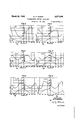
- Fig. 3 is a graph illustrating particular sets of selected orientation angles for the quartz crystal plate I shown in Fig. 1 that may be utilized to produce substantially zero temperature coefficient of frequency when vibrating in the high frequency or XY' shear vibration mode of motion at a frequency determined by the thin dimension t of the plate I;
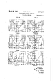
- Figs. 4 to are additional graphs illustrating particular sets of orientation angles for every ten degrees of angle 0 and the corresponding values of piezoelectric activity moduli d'zs for the quartz crystal plate I having substantially zero temperature coefficient of frequency when vibrating in the same relatively high frequency XY shear mode of motion at a frequency determined by the thin dimention t of the plate I as illustrated in the curves of Fig. 3;
- Fig. 16 is a graph similar to Fig. 3 illustrating particular zero temperature coefficient of frequency orientation angles for vibrations in a shear mode of motion but at a relatively low frequency determined by a large dimension 2 of the plate I;
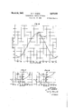
- Figs. 17 to 24 are graphs similar to those of Figs. 4 to 15 but illustrating the orientation angles and corresponding values of the piezoelectric activity moduli d'zd for vibrations in the low frequency face or Z'a: shear mode of motion at a relatively low frequency determined by the large dimension 1 of the quartz plate -I.
- Fig. 25 is a graph illustrating additional sets of orientation angles for the quartz plate I to produce zero temperature coefficient of frequency and also maximum values of piezoelectric activity in the'low frequency Z'x shear mode of vibration.
- Quartz crystals may occur in two forms, namely, right-hand and left-hand.
- a crystal is designated as right-hand if it rotates the plane of polarization of plane polarized light traveling along the optic or Z axis in a clockwise direction when facing in the direction of propagation of the light, and is designated as left-hand if it rotates the plane of polarization in the counter-clockwise direction. If a compressional stress be applied to the ends of the electric axis of a quartz crystal body and not removed, a charge will be developed which is positive at the positive end of the electric axis and negative at the negative end of the electric axis for either right-hand or left-hand crystals.
- the magnitude and sign of the charge may be measured with a vacuum tube elec'trometer, for example. It is necessary to distinguish between a lefthanded and right-handed crystal in specifying the direction for measuring the angles 0, and As may be seen from Fig. 1, the angle is always positive since it measures the angle between Z and Z. Similarly, the angles #1 and 'y are always positive. The angle 0, however, can be either positive or negative and the sense of it differs for a right-handed or a left-handed crystal.
- a positive angle 0 as a counter-clockwise rotation of the ZZ plane around the Z axis for a right-handed crystal measured from the positive x axis (determined by a compression).
- a positive angle 0 is measured in a clockwise direction.
- this'speciflcation follows the standard terminology as applied to quartz which employs orthogonal X, Y and Z axes to designate the orthogonal electric, mechanical and optic axes respectively of the piezoelectric quartz crystal material and which employs X, Y and Z to designate the directions of axes or surfaces of a piezoelectric body angularly oriented with respect to the orthogonal X, Y and Z crystallographic axes thereof.
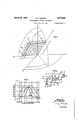
- the orientation angles 4:, 0, 'y designate the effective angular position of the crystal in degrees as measured from the optic crystallographic axis Z and from the electric crystallographic axis X as shown in Fig. 1 and as described hereinafter.
- Fig. 1 illustrates a perspective view of a piezoelectric quartz crystal element or plate I of substantially rectangular parallelepiped shape and having a length Z, a width w, and a thickness or small dimention t.
- the directions of the axes and the surfaces of the piezoelectric body I with respect to the orthogonal crystallographic axes X, Y and Z thereof are designated by the orthogonal X, Y and Z' axes, respectively.
- the Y axis is normal or perpendicular to the major plane and to the twomajor or electrode faces of the plate I' and extends in the direction of the thickness dimension t.
- the crystal plate I as illustrated in Fig. 1, has two parallel major faces separated by a uniform thickness distance i which may be made relatively small compared to the dimensions 1 and w of the two large major faces in order to prevent mechanical coupling with undesired modes of vibration therein.
- the vibration of the quartz plate I may be in the XY' shear mode of motion at a relatively high frequency determined by the thickness dimension t and depending on the elastic constant 066', or may be at a relatively low frequency determined by the large dimensions 1 and w and depending in the elastic constant S'55.
- a relatively lowfrequency vibration may be obtained in the range from 30 to 500 or more kilocycles per second, for example.
- a relatively high frequency vibration may be obtained in the range above 1000 kilocycles per second, for example.
- suitable electrodes such as the conductive electrodes 2 and 3, suitable mountings and suitable circuits may be associated with the crystal I to excite and drive the crystal at a selected characteristic frequency thereof.
- the quartz plate I may be cut from the mother crystal at selected angles 0, and v or 1/ with respect to the crystallographic axes to obtain a desired temperature coefficient of frequency as hereinafter disclosed.
- the electric field E may be applied by the electrodes 2 and 3 along the Y or thickness t direction of the plate I and, for high frequencies, an XY' shear mode of vibration may be utilized. This XY' shear high frequency vibration is not adversely affected when the plate I is rigidly clamped either around the periphery margins of the major surfaces if the plate is circular, or at the four corners if the plate I is square or rectangular as illustrated.
- a mechanically rigid holder arrangement may therefore be obtained which is particularly suitable for' mobile radio applications.
- the quartz plate I may be clamped at its periphery margins to discriminate in favor of the high frequency shear vibrations as against the flexural vibrations, as disclosed for example in Figs. 8 and 9 of U. S. Patent 2,173,589, granted September 19, 1939, on application Serial No. 702,334, filed December 14, 1933, by W. P. Mason the present applicant and R. A. Sykes.
- the plate I may be nodally clamped by mountings as fllustratecl, for example, in U. S. Patent 2,032,865, granted March 3, 1936, to C. A. Bieling, in Fig. 10 of U. S. Patent 2,173,589, granted September 19, 1939, on
- the electrodes 2 and 3 may conveniently consist of a thin coating of metal such as aluminum formed integral with or otherwise closely associated with the two opposite major faces of the crystal I.
- the electrodes 2 and 3 may be electrically connected in circuit with any suitable system such as, for ex ample, an oscillation generating system or an electric wave filter system to excite the crystal plate I at a vibration frequency determined by the thickness dimension t or by the dimension l or dimensions 1 and w. It will be understood that the frequency may be any desired. value dependent upon the frequency-controlling dimension or dimensions selected.
- Conductive connectors I8 and I9 may be utilized to electrically connect the crystal I and its electrodes 2 and I in circuit with a vacuum tube oscillation generator 20 as'iliustrated in Fig. 2, for example, to control the. frequency of oscillations thereof.
- the particular oscillator 20 includes' a vacuum tube 2I having a cathode 22, a grid 23, and a plate electrode 24.
- the output circuit of the oscillator 20 may include a tuning coil 25 connected in parallel circuit relation with a variable condenser 26.
- a by-pass condenser 21 may connect the mid-point of the tuning coil 25 with the cathode 22.
- a feed-back condenser 20 may feed back radio frequency oscillations to the grid electrode 23.
- Suitable batteries 28 and 30 as illustrated may energize in a known manner the cathode 22 and plate electrode 24, respectively.
- a grid-leak resistance lI and a milliammeter M may be connected between the grid 23 and the cathode 22.
- the crystal I may be utilized to control the frequency of oscillationsof any suitable oscillator, the particular oscillator-20 being shown in Fig. 2 as an illustrative example only;
- the conductive connectors I8 and I9 may be utilized to operatively connect the crystal I in circuit with an electric wave filter system to form a selective element thereof as illustrated, for example, in application Serial No. 65,022, filed February 21, 1936, by W. P. Mason now U. S. Patent 2185599, dated January 2, 1940, or in applicants publication entitled Electrical wave filters employing quartz crystals as elements, Bell System Technical Journal, page 433, July 1934.
- the crystal I when-excited in the low frequency shear mode of motion may conveniently have integral plated electrodes 2 and 3 and may be rigidly nodally clamped at the center of the major surfaces thereof by means of a pair of coaxial metallic clamping projections 38 and 39 supported and resiliently controlled by metallic springs 40 and 4
- any suitable electrodes and circuit arrangement may be utilized for exciting the crystal I in the mode of vibration described.
- the resultant temperature coefiicient T is zero, where the angle 1/ is used for the specification of the component temperature coefficients thereof 11 to m, the corresponding angle 1 may be obmay be treated as follows: tained from the relation:
- the temperature coeflicient of density 01' the quartz is a constant independent oi orientation 5 cos 7:511
- the CMTCGGI CHTCH 1 n em smit cos .p polar coordinates of the shear or length axis Z are 0 and as shown in Fig. 1, where 0 meas- +CMTM c052 ures the angle that the plane determined by the shear axis 2' and )the optic axis Z is rotated in ul sin [sin 30 cos (2 cos 4c a counterclockwise direction from the electric crystallographic axis X, and where it represents 1+3 cosh the angle between the optic crystallographic axis 39 Sm '1 Z and the shear axis Z which is measured in this plane.
- These two angles 0 and o determine one m 5mg *81112 Sm: (9)
- Equation 9 The values of mentioned in Equation 9 were measured by W. Voight, "Lehrbuch der 1n the direction of the width dimension w, and
- Equation 2 a 7900 sin sin ,0 cos lll+ 6330 cos 1595 sin Jsin 39 cos 5(2 cos 4 b+sin 2% sin 4) 10 2 +c0s 3o sin 4( 93c0 sin (lsin Sim 2c
- Equation 2 The other terms in Equation 2 are:
- Equation 2 may be reduced to the numerical equation:
- T; [4.5+5.8 sin sin ll grees together with the corresponding values of angles e and 7 to obtain a zero temperature coexhibiting shear strain at a frequency determined by the thickness t of. the crystal I.
- the quartz plate I of Fig. 1 will have its width axis w along an electric axis and its major plane parallel to an electric axis X and inclined 49 degrees with respect to the optic axis Z to produce a zero temperature coefllcient of frequency at the mode of vibration exhibiting shear strain 1 and at a frequency determined by the thickness dimension t.
- the electrode faces and the major plane of the quartz plate I may be parallel to one of the three mechanical crystallographic axes Y and inclined at an acute angle 4 with respect to the optic crystallographic axis Z, and the axes Z and X of the major plane of the plate I may be inclined with respect to said mechanical and optic crystallographic axes to produce a zero or other desired predetermined temperature-coefficient of shear vibration frequency at a frequency determined by the thickness t of the quartz plate I.
- the thickness dimension tof the plate I may be normal or perpendicular to a mechanical axis Y and inclined at an angle to the optic axis Z to produce the zero temperature coeilicient of frequency.
- the electrode faces and the major plane of the quartz plate I may be parallel to an electric axis X and inclined at an acute angle qb with respect to the optic axis Z, and the axes Z and X of the major plane may be inclined at acute angles with respect to said electric and optic axes to produce a zero or other desired predetermined temperature coeflicient of XY' shear vibration frequency at a given temperature and at a relatively'hlgh frequency de-,
- the thickness dimension t or axis Y may be normal to one of the three electric axes and inclined at an acute angle to the optic axis Z and the other two orthogonal axes X and Z may be inclined at acute angles to said electric and optic axes.
- the maximum or higher values of the piezoelectric driving moduli d'zs for other orientations may be similarly obtained from the remaining d'it curves in the several figures.
- the major plane, faces and orthogonal axes X, Y and Z' of the quartz plate I may be inclined to or disposed intermediate all of the electric, mechanical and optic crystallographic axes X, Y and Z to produce the While the temperature coefficients of the S and C elastic constants of quartz herein given in Equation 14b and Equation 9b are correct within about 5 per cent, it will be understood that they may be more accurately determined by more accurate measurements.
- Equation 14 Inserting in Equation 14 the numerical values /of the temperature coefilcients and the S c0nstants of quartz as given in Equations 14a and 1412, the equation for the temperature coeilicient of frequency becomes selected temperature coemcient of shear vibration frequency at a frequency determined by the thickness t of the quartz plate I.
- Another group of crystals for which zero temperature coeflicient of shear frequency vibrations may be obtained comprises the relatively low frequency ZX' shear vibration crystals wherein the frequency is determined not by the thickness dimension t as illustrated in connection with Figs. 3 to and Equation 11 but mainly by the larger dimensions 2 and w of the crystal I.
- the frequency of such low frequency shear crystal I of square or nearly square shape may be given by the formula:
- the temperature coefficients of the S elastic constants of quartz are substantially as follows:
- Ts +120 10- per degree C.
- T. - ⁇ -194.6 10 per degree C.
- lTs -108 X 10- per degree C.
- the low frequency shear crystals having zero temperature coeificient of frequency are obtained by selecting the values of 0, 45 and ⁇ l/ or 'y in Equation 15 which make the resultant temperature coefllcient of frequency T: equal to zero.
- Figs. 16 to 25 show some of the quartz crystal orientations as obtained from Equation 15 which produce substantially zero temperature coefficient of frequency in a mode of vibration exhibiting shear strain at a frequency determined by the equal dimensions 1 and w of the quartz crystal plate I.
- Figs. 17 to 24 are similar to those of Figs. 4 to 15 but illustrate the orientation angles and corresponding values of the piezoelectric moduli d'zs for shear vibrations at a relatively lower frequency as determined by the large dimension 1 of the crystal plate I.
- the curves in Figs. 17 to 24 are plotted for every 15 degrees of' angle 0 from 0 to 105 degrees with the corresponding values of angles 5 and 'y.
- the angle 0 repeats in cycles of 120 degrees.
- CT computed tomography
- the square quartz plate I of Fig. 1 will have its width axis 10 along an electrical axis X and its major plane and opposite electrode or major surfaces parallel to an electric axis and inclined +382 degrees with respect to the optic axis Z to produce a zero temperature coefficient of frequency when vibrated at a frequency determined by the large dimensions 1 and w.
- the square quartz plate I of Fig. 1 will have its major plane parallel to an electric axis X and inclined 53 degrees with respect to the optic axis Z to obtain zero temperature coefficient of frequency at the low frequency ZX' shear-mode of vibration.
- Numerous other sets of values of 0, 1: and 7 may be similarly selected from the curve of Fig. 16 and from Equation 15 to obtain other square-shaped low-frequency quartz crystals having zero temperature coeflicient of frequency.
- the electrode faces and the major plane of the quartz plate I may be parallel to one of the three mechanical crystallographic axes Y and inclined at an acute angle c to the optic axis Z, and the axes Z and X of the major plane of the plate I may be inclined with respect to said mechanical and optic axes to produce -a zero or desired temperature coeiiicient of shear frequency at a frequency of vibration determined by the large dimension 1 of the quartz plate I.
- the electrode faces and the major plane of the quartz.
- Equation 11 defines a rectangular quartz plate and Equation 15 a square or nearly square quartz plate, the axis Z of which is specified with respect to the crystallographic axes by the polar coordinate angles 0 and 4: which determine respectively the plane of the axis Z measured from the electric axis X and the angle of the axisZ' in that ZZ' plane measured from the optic axis Z, and the width axis X of which is at an angle 7 from the optic axis Z, these angles 0, 1: and 1' being so chosen that simultaneously they satisfy Equation 11 or 15 for a zero or other specified value of the temperature coeflicient of frequency Tr.
- Numerousother sets of values for 0, e and Y may be selected from Equations 11 and 15 and from the curves in Figs. 3 to 25, to obtain quartz plates I which may have substantially a zero or other desired temperature coeihcient of shear vibration frequency, and which may also at the same time have the maximum or higher values of piezoelectric activity dzs or d'zs.
- Other piezoelectric driving constants dn, d'zz, dn, and d'u may be present but do not effecn tively drive the particular shear mode of motion herein considered.
- the (1'25 constant thereof equals 7:03, and the (1'21, d'22, (1'23, ,d'24
- Fig. 25 show the paths along men the piezoelectric constant (1'25 of such 2- 0 temperature coefficient quartz crystal axes, there are two relatively high-frequency quartz crystal plates as indicated as AT and ET in Fig. 3,.for example, that will give a zero temperature coefficient of frequency when vibrating in shear along their thinnest dimension t, and also that there are two relatively low-fre quency quartz crystal plates, indicated as CT and DT in Fig. 15, for example, that will give a zero temperature coefficient of frequency when vibrating in shear at a frequency determined by their large dimensions.
- the temperature coefficient of frequency thereof may be rendered practically zero, the amount of power that plates is a maximum and accordingly such quartz plates I having orientation angles of 4a, 6 and 7 .corresponding to the path of such dotted line curves may have the larger values of piezoelectric activity as well as substantially zero temperature coefficient of frequency when excited in the particular low frequency shear mode of vibration referred to.
- the quartz plate I may have an orientation of 5:38 degrees 20, 6:90 degrees and :90 degrees to produce zero temperature coefiicient of frequency and obtain a relatively large value of piezoelectric activity as measured by the piezoelectric constant d'25.
- Other orientations may be similarly selected from the dotted line curves of Fig. 25 to obtain quartz plates having zero temperature coefiicient of frequency and large piezoelectric activity.
- crystal plates are cut from a natural quartz crystal in such a manner that their principal or major plane is rotated about one of the electric crystallographic or X can be controlled without fracture of the crystal I may be increased, the frequency spectrum may be simplified, and the piezoelectric activity may be increased, and that such quartz crystals may be rigidly clamped in the holder and utilized as j circuit elements for frequency control at radio frequencies in any suitable system such as an oscillation generating system or an electric wave filter system.
- the secondary frequency spectrum of the quartz plate may consist of overtones of low frequency vibrations which are mechanically coupled to the desired vibration and may cause dis continuities or hops in the characteristic temperature-frequency curves of the crystal.
- the plate may be so adjusted that there are no such discontinuities in the region where it is expected to operate or the effect of any secondary spectrum may be minimized or eliminated by selecting such angular orientations of the crystal that the magnitude of the elastic constant responsible for the undesired coupling is reduced to zero or other ineffective value without at the same time introducing other undesired couplings, in accordance with the principles disclosed in a copending application Serial No. 702,334, filed December 11, 1933, by W. P. Mason and R. A. Sykes, now U. S.
- the values of the temperature coefficients of stantially free from coupling with any other mode of motion therein may be utilized to substantially locate all the regions of zero or other desired predetermined temperature coefllcient or frequency for any type of vibration in long thin rods; plates or in other shapes of quartz bodies as well as in those particularly illustrated herebefore.
- the six principal modes of vibration are the three extensional modes Xx, Y1, and Zr, and the three shear modes x1, Ya and Zr.
- the Xv shear mode of motion and the Zx' shear mode of motion are particularly disclosed herein in connection with the Equations 11 and 15, respectively, and the graphs derived therefrom as shown in Figs. 3 to 25.
- the frequency of a long thin quartz bar or rod is governed by the S22 coeflicient rather than by the Cat coefiicient as given in Equation 1; and calculations, following the principles herein given, may be similarly made to obtain all the regions that produce a zero or other desired predetermined temperature coeflicient of frequency in the longitudinal or extensional mode of vibration for all rotative positions parallel or intermediate the crystallographic axes.
- quartz bar In a particular case such a relatively long thin quartz bar having its major or longitudinal axis perpendicular to an electric axis and inclined at an angle substantially +4.5 degrees with respect to the orthogonal mechanical crystallographic axis, produces substantially zero temperature coeiilcient of frequency when excited, as by a pair of opposite electrodes on the two opposite major surfaces thereof perpendicular to the electric axis, in the fundamental longitudinal mode of vibration free from coupling with other modes of vibration therein such as iiexural modes.
- Suitable dimensional ratios such as for example a ratio of length of 20 millimeters, width of 3 millimeters and thickness of 0.5 millimeter may be utilized in such a long bar crystal to avoid undesired flexural coupled modes.
- a quartz piezoelectric element having a substantially rectangular major plane, and means for applying an electric field thereto in the direction of its thickness axis or smallest dimension perpendicular to said major plane for vibrating said element in a shear mode of motion at a frequency which is determined substantially by said thickness axis dimension, said thickness dimension being made of a value in accordance with the value of said frequency, the width or X axis of said major plane being inclined at an acute angle with respect to the Z axis, the length or Z axis of said major plane being inclined at an acute angle with respect to said Z axis, and the plane formed by said Z and Z axes bein inclined at a selected angle with respect to an X axis as measured in the plane of said X axis and a Y axis, said acute angles and said selected angle being a set of angles of values substantial- 1y as given by the solid line curves of Figs. 4 to 15 at a point thereon corresponding to an effective or relatively large value near to a maximum value of the
- a quartz piezoelectric element having a substantially rectangular major plane, and means for applying an electric field thereto in the direction of its thickness axis or smallest dimension efilcient of frequency, variations may be made therein in practice to adjust the temperature coeflicient of frequency of the quartz body to a more precise value.
- said thickness dimension being made of a value in accordance with the value of said frequency
- the width or X axis of said major plane being inclined at a selected angle with respect to the Z axis
- the length or Z axis or said major plane beinig inclined at an acute angle with respect to saidZ axis
- the plane formed by said Z and Z axes being inclined at a selected angle with respect to an X axis as measured in the plane of said X axis and a Y axis, said angles being a set ofangles of values substantially as given by the solid line curves 'of Figs.
- a quartz piezoelectric element having a substantially rectangular major plane, and means for applying an electric field thereto in the direcsaid elementin a shear mode of motion at a frequency whichis determined substantially by said thickness axis dimension, said thickness dimension being made of a value in accordance with the value or said frequency, the width or X axis of said major plane being inclined at a selected angle with respect to the Z axis, the length or Z axis of said major plane being inclined at an acute angle with respect to said Z axis, and the plane formed by said length axis and said Z axis being inclined with respect to a compression positive X axis at a positive angle of substantially degrees as measured in the plane of said X axis and a Y axis, saidangles being a set of angles of values substantially as given by the solid line curve of Fig.
- a quartz piezoelectric element having a substantially rectangular major plane, and means for applying an electric field thereto in the direction of its thickness axis or smallest dimension perpendicular to said major plane for vibrating said element in a shear mode of motion at a frequency which is determined substantially by said thickness axis dimension, said thickness dimension being made of a value in accordance than 90 degrees, said point corresponding to an effective or relatively large value of piezoelectric constant as given by the broken line curve oi said Fig. 4, to obtain a relatively small temperature coeflicient of frequency and a relatively large electromechanical coupling when vibrated in said shear mode of motion.
- a quartz piezoelectric element having a substantially rectangular major plane, and means for applying an electric field thereto in the direction of its thickness axis or smallest dimension with the value of said frequency, the width or X axis of said major plane being inclined at a selected angle with respect to the Z axis, the. length or Z axis of said major plane being inclined at an acute angle with respect to said Z- axis, and theplane formed by said length axis and said Z axis being inclined with respect to a compression positive X axis at a positive angle of substantially 90 degrees as measured in the plane 01 said X axis and a Y axis, said angles being a set of angles of values substantially as 5.
- a quartz piezoelectric element having a substantially rectangular major plane, and means for applying an electric field thereto in the direction of its thickness axis or smallest dimension perpendicular to said major plane for vibrat ing said element in a shear mode or motion at a frequency which is determined substantially by said thickness axis dimension, the width or X' compression positive X axis at a positive angle of substantially 60 degrees as measured in the plane of said X axis and a Y axis, said angles being a set of angles 01 values substantially as given by the solid line curve 01 Fig.
- a quartz piezoelectric element having a substantially square major plane, and means for axis of said major plane being inclined at a selected angle with respect to the Z axis, the
- a piezoelectric quartz crystal plate of'low temperature coeiiicient of shear mode frequentkcy said plate having substantially square major cordance with the value"of said frequency, said X axis being inclined with'respect to the Z axis at .an angle 7 which is substantially one of the positive angles within the range from 55 to 85 and from'95 to 125 degrees, said Z axis being inclined with respect to the Z axis at a positive angle within the range of angles substantially from 38 to 70 degrees, and the plane formed by said Z and Z axes being disposed with respect to a compression positive X axis at a positive angle as measured in the plane of said X axis and a Y axis, said 1 c and 0 angles being a set of 7, and 0 angles of related values substantially as given by the solid line'curves of Figs. 17 to at a point corresponding to an eflective or relatively large value of the piezoelectric driving constant as given by the broken line curves thereof.
- a quartz piezoelectric element having a substantially square major plane, and means for applying an electric field thereto in the direction of its thickness axis dimension perpendicular to said major plane for vibrating said element in a shear mode of motion at a frequency which is determined substantially by the dimensions of said major plane, said dimensions of said major plane being made of values in accordance with the value of said frequency, the width or X' axis of said major plane being inclined at a selected angle with respect to the Z axis, the length or Z' axis of said major p ane being inclined at an acute angle with respect to said Z axis, and the plane formed by said Z and Z axesbeing inclined at.a selected angle with respect to an X axis as measured in the plane of said X axis and a Y.
- angles being a solid line curves of Figs. 19 and 23 at a point thereon where said first-mentioned angle is one of the values within the range from morethan 60 to less than 90 degrees and from more than 90 to less than 120 degrees, to obtain a relatively small temperature coefiicient of frequency and a relatively large electromechanical coupling when vibrated in said shear mode of motion.
- a quartz piezoelectric element having a substantially square major plane, and means for applying an electric field thereto in the direction of its thickness axis dimension perpendicular to said major plane for vibrating said element in a shear mode of motion at a frequency which is determined substantially by the dimensions of said major plane, the width or X axis of said major plane being inclined at a selected angle with respect to the Z axis, the length of Z axis of said major plane beinginclined at an acute angle with respect to said Z axis, and the plane formed by said length axis Z' and said Z axis being inclined at a selected angle with respect to an X axis as measured in the plane of said X axis and a Y axis, said angles being a set of angles of values substantially as given by the solid line curves of Fig.
- a quartz piezoelectric element having a substantially square major plane, the width or X axis of said major plane being inclined to the Z axis at a positive angle of substantially 105 degrees, the length or Z axis of said major plane being inclined to said Z axis at a positive angle of substantially 53 degrees, and the plane of said length axis and said Z axis being disposed with respect to a compression positive X axis at a positive, angle of substantially 15 degrees as measured in the plane of said X axis and a Y axis, to obtain a relatively small temperature coefilcient of frequency and a relatively large electromechanical coupling when subjected to an electric field in the direction of the thickness axis dimension perpendicular to said major plane and vibrated in a shear mode of motion at a frequency which is determined substantially by said major plane dimensions.
- a quartz piezoelectric element having a substantially squar major plane, the width or X axis of said major plane being inclined to the Z axis at a positive angle of substantially 75 degrees, the length or Z axis of said major plane being inclined to said Z axis at a positive angle of substantially 52 degrees, and the plane of said length axis and said Z axis being disposed with respect to a compression positive X axis at a positive angle of substantially degrees as measured in the plane of said X axis and a Y axis, to obtain a relatively small temperature coefficient of frequency and a relatively large electromechanical coupling when subjected to an electric field in the direction of the thickness axis dimension perpendicular to said major plane and vibrated in a shear mode of motion at a frequency which is determined substantially by said major plane diclosely adjacent a broken line curveof said Fig.
- a quartz piezoelectric element having a substantially square major plane, the width or X axis of said major plane being inclined to the Z axis at a positiveiangleof substantially 120 degrees, the length on: Z axis of said major plane being inclined to said Z axis at a positive angle of substantially 5'7 degrees, and the plane of said mensions.
- a quartz piezoelectric element having a substantially square major plane, the width or X axis of said major plane being inclined to the Z axis at a positive angle of substantially 55 degrees, the length or Z' axis of said major plane being inclined to said Z axis at a positive angle of substantially 60 degrees, and the plane of said length axis and said Z axis being disposed with respect to a compression positive X axis at a positive angle of substantially 60 degrees as measured in the plane of said X axis and a Y axis, to obtain a relatively small temperature c0- efiicient or frequency and a relatively large electromechanical coupling when subjected to an electric field in the direction of the thickness axis dimension perpendicular to said major plane and vibrated in a shear mode of motion at a frequency which is determined substantially by said major plane dimensions.
- a quartz piezoelectric element having a substantially square major plane, the width or X axis of said major plane being inclined to the Z axis at a positive angle of substantially degrees, the'length or Z axis of said major plane being inclined to said Z axis at a positive angle of substantially 48 degrees, and the plane of said length axis and said Z axis being disposed with respect to a compression positive x axis at. a positive angle of substantially 60 degrees as measured in the plane of said X axis and a Y axis, 1
- a quartz piezoelectric element having a substantially square major plane, the width or X axis of said major plane being inclined to the Z axis at a positive angle of substantially 105 degrees, the length or Z axis of said major plane being inclined to said Z axis at a positive angle of substantially 40 degrees, and the plane of said length axis and said Z axis being disposed with respect to a compression positive x axis at a posi-' tive angle of substantially 75 degrees as measured in the plane of said X axis and a Y axis, to obtain a relatively small temperature coeillcient of frequency and a relatively large electromechanical coupling when subjected to an electric field in the direction of the thickness axis dimension perpendicular to said major plane and vibrated in a shear mode of motion at a frequency which is determined substantially by said major plane dimensions.
- a quartz piezoelectric element having a substantially square major plane, the width or X axis of said major plane being inclined to the Z axis at a positive angle of substantially '15 degrees, the length or Z axis of said major plane being inclined to said Z axis at a positive angle of substantially 40 degrees, and the plane of said length axis and said Z axis being disposed with respect to a compression positive X axis at a positive angle of substantially 105 degrees as 3 measured in the plane 0!
Description
VALUE 0F 11v DEGREES h March 24, 1942. 2w; P. MAISON 2,277,245
' P PIEZOELEQTRIC CRYSTAL APPARATUS Filed Nov. 25, 1956 e Shet-Sheat 1 INVENTOR m R MASON VALUEOFQ/IVDEGREES A TTORNEY March 24, 1942. p, A N 2;277,245
PIEZOELEC'IRIC CRYSTAL APPARATUS Filed Nov. 25, 1936 6 Sheets-Sheet 2 F/G.4 FIGS I so 0-!0 Q 55"--% arc- VALUE or y was or r F/G.8 F/6.9
I i a so I o w 8540 8'50 By M. R MASON A 7' TORNEV March 24, 1942. MASQN 2,277,245
' PIEZOELECTRIC CRYSTAL APPARATUS 7 Filed Nov. 25, 19 36 S'Shee'cS-Sheer. 5
FIG/0 FIG.
VALUE OF I VALUE OF T FIG/4 II VALUE'OF'Y' FIG. /5
Q a v 2 q I VALUE OF 1" 41.05 OF T /NVENTOR By W. P. MASON A TTORNEV March 24, 1942'. w. P. MASON 2,277,245
PIEZOELECTRIC CRYSTAL APPARATUS Filed Nov. 25, 1936 6 Sheets-Sheet 5 FIG. /9 FIG. 20
VALU OF 45 F1623 FIG. 24
HUI/,0
VALUE OF? VALUE OF Y INVENTO/P W P. MASON ATTORNEY March 24, 1942. w. P. MASON 2,277,245
PIEZOELECTRIC CRYSTAL APPARATUS Filed Nov. 25, 1936 6 Sheets-Sheet 6 as 90 VALUE 0F Y IN DEGREES 3 2 8 '9 3 3 3 3 a 2 sage/93a /v/ a .1'0 307m /N V5 N TOR By W. R MASON A 7" TO/PNEV Patented Mar. 24, 1942 rmzomc'rarc caYs'rAL arrm'rus Warren PeMason, West Orange, N. 3., asslgnor to Bell Telephone Laboratories, Incorporated, New York, N. Y., a corporation of New York Application November 25, 1938, Serial No. 112,685
(Cl. I'll-32?) 17 Claims.
This invention relates to piezoelectric apparatus and particularly to the angular orientation of the faces and of the physical or geometrical axes of piezoelectric crystal bodies with respect to the crystallographic axes thereof to control the trio activity.
frequency.
riation.
quency thereof.
position of its surfaces and axes with respect to the crystallographic axes thereof results in a compensating relationship between the several components of the temperature coefllcients of density, dimension, and elastic constant which together make up the resultant temperature cochange The effects of temperature upon the vibration freemcient of frequency of the body. In the case quency thereof and to provide elements such as of quartz this may involve a rotation ororientapiezoelectric quartz crystals suitable for use as tion of the body such that the surfaces or axes frequency-determining elements in oscillation thereof are inclined to two or more of the crysgenerating systems or in electric wave filter tallographic axes of the quartz. systems or other networks, for example. In accordance with this invention, piezoelectric One of the objects of this invention is to concrystals such as quartz crystal elements may be trol the effect of temperature upon the vibration oriented with respect to the elec ric. m h ni l frequency of a piezoelectric body. and optic crystallographic axes thereof in such Another object of this invention is to provide manner as to obtain all the angles of the desired piezoelectric crystals having such multiple angle orientations giving zero or the lowest value of orientations with respect to the crystallographic m atu eoeflieient of f n y f a y axes thereof as to produce a substantially zero ode of vi atio 8110 -8, p Shelli or other desired predetermined temperature 00- wave modes of vibration which are particularly emcient of vibration frequency. illustrated herein. Thus, the temperature co- Another object of this invention i to permit efllcients of frequency for any angular orientatemperature regulating apparatus for piezoelection for any mode of vibration may be obtained tric bodies to be simplified or eliminated. and whole surfaces of low temperature well- Another object of this invention is to provide c ent quartz r sta ay e ob a ed w ch ay piezoelectric crystals having high piezoelectric have other advantages such as, large values of driving constants and large values of piezoelecelect omec a c coup ns o pi oe ec c activity, and small mechanical coupling with any It is well known that a' piezoelectric quartz o e mod o h y u des e d s o v ystal may produce a vibration of fairly confl O e stant frequency and yet there may exist various n apa i u a e odim nt. e c ys a maybe factors affecting the constancy of it vibration quartz and may have such selected double or Among them, the variation of t triple angular orientations of its axes or surfaces operating temperature of the crystal is a i with respect to the crystallographic axes thereportant factor. It may be desired therefore to of as to constitute themaior effective means for obtain a crystal having its vibration frequency producing zero t p ra ur fli nt f substantially independent of its temperature vaquency to thereby render the frequency substantially independent of temperature As the temperature of a piezoelectric quartz throughout a given temperature ran ebody is changed, the dimensions, the densit and multiple orientation angles may be such as to the elastic constants thereof which relate me- 4" p d o ta r t atur oefl i nt chanical stresses to corresponding mechanical f frequency for the crystal when vibrated in a strains, also tend to change, and may bring about shear mode of motion at a relatively high fre- 9. corresponding change in the vibrating freq n determined y the thickness or smallest dimension of the crystal element, or when vi- In accordance with this inventi n, th t brated in a shear mode of motion at a frequency ature coefficient of frequency of a piezoelectric determined by m other ension or dimenbodylnay be made substantially zero or th r sions thereof, as for example, by one or more desired predeterminedvalue by so cutting the of the major surface dimensions or periphery body from the natural crystal that the relative tblgrieof to obtain a relatively low frequency vit on.
For a clearer understanding of the nature of this invention and the additional features and objects thereof, reference is made to the follow-' circuit arrangement that maybe utilized to excite I the crystal plate shown in Fig. 1;
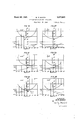
Fig. 3 is a graph illustrating particular sets of selected orientation angles for the quartz crystal plate I shown in Fig. 1 that may be utilized to produce substantially zero temperature coefficient of frequency when vibrating in the high frequency or XY' shear vibration mode of motion at a frequency determined by the thin dimension t of the plate I;
Figs. 4 to are additional graphs illustrating particular sets of orientation angles for every ten degrees of angle 0 and the corresponding values of piezoelectric activity moduli d'zs for the quartz crystal plate I having substantially zero temperature coefficient of frequency when vibrating in the same relatively high frequency XY shear mode of motion at a frequency determined by the thin dimention t of the plate I as illustrated in the curves of Fig. 3;
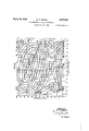
Fig. 16 is a graph similar to Fig. 3 illustrating particular zero temperature coefficient of frequency orientation angles for vibrations in a shear mode of motion but at a relatively low frequency determined by a large dimension 2 of the plate I;
Figs. 17 to 24 are graphs similar to those of Figs. 4 to 15 but illustrating the orientation angles and corresponding values of the piezoelectric activity moduli d'zd for vibrations in the low frequency face or Z'a: shear mode of motion at a relatively low frequency determined by the large dimension 1 of the quartz plate -I.
Fig. 25 is a graph illustrating additional sets of orientation angles for the quartz plate I to produce zero temperature coefficient of frequency and also maximum values of piezoelectric activity in the'low frequency Z'x shear mode of vibration.
Quartz crystals may occur in two forms, namely, right-hand and left-hand. A crystal is designated as right-hand if it rotates the plane of polarization of plane polarized light traveling along the optic or Z axis in a clockwise direction when facing in the direction of propagation of the light, and is designated as left-hand if it rotates the plane of polarization in the counter-clockwise direction. If a compressional stress be applied to the ends of the electric axis of a quartz crystal body and not removed, a charge will be developed which is positive at the positive end of the electric axis and negative at the negative end of the electric axis for either right-hand or left-hand crystals. The magnitude and sign of the charge may be measured with a vacuum tube elec'trometer, for example. It is necessary to distinguish between a lefthanded and right-handed crystal in specifying the direction for measuring the angles 0, and As may be seen from Fig. 1, the angle is always positive since it measures the angle between Z and Z. Similarly, the angles #1 and 'y are always positive. The angle 0, however, can be either positive or negative and the sense of it differs for a right-handed or a left-handed crystal.
In order to agree with standard usage, one may define a positive angle 0 as a counter-clockwise rotation of the ZZ plane around the Z axis for a right-handed crystal measured from the positive x axis (determined by a compression). For a left-handed quartz crystal, a positive angle 0 is measured in a clockwise direction.
It will be noted that this'speciflcation follows the standard terminology as applied to quartz which employs orthogonal X, Y and Z axes to designate the orthogonal electric, mechanical and optic axes respectively of the piezoelectric quartz crystal material and which employs X, Y and Z to designate the directions of axes or surfaces of a piezoelectric body angularly oriented with respect to the orthogonal X, Y and Z crystallographic axes thereof. Where the orientation is obtained by multiple rotations as illustrated in Fig. 1, for example, the orientation angles 4:, 0, 'y designate the effective angular position of the crystal in degrees as measured from the optic crystallographic axis Z and from the electric crystallographic axis X as shown in Fig. 1 and as described hereinafter.
Referring to the drawings, Fig. 1 illustrates a perspective view of a piezoelectric quartz crystal element or plate I of substantially rectangular parallelepiped shape and having a length Z, a width w, and a thickness or small dimention t. The directions of the axes and the surfaces of the piezoelectric body I with respect to the orthogonal crystallographic axes X, Y and Z thereof are designated by the orthogonal X, Y and Z' axes, respectively. The Y axis is normal or perpendicular to the major plane and to the twomajor or electrode faces of the plate I' and extends in the direction of the thickness dimension t.
The crystal plate I, as illustrated in Fig. 1, has two parallel major faces separated by a uniform thickness distance i which may be made relatively small compared to the dimensions 1 and w of the two large major faces in order to prevent mechanical coupling with undesired modes of vibration therein. The vibration of the quartz plate I may be in the XY' shear mode of motion at a relatively high frequency determined by the thickness dimension t and depending on the elastic constant 066', or may be at a relatively low frequency determined by the large dimensions 1 and w and depending in the elastic constant S'55. When the crystal plate I is driven at a frequency determined by the major surface dimensions 1 and w thereof, a relatively lowfrequency vibration may be obtained in the range from 30 to 500 or more kilocycles per second, for example. And when the crystal plate I is driven at a frequency determined by the thinnest dimension t, a relatively high frequency vibration may be obtained in the range above 1000 kilocycles per second, for example. It will be understood that suitable electrodes such as the conductive electrodes 2 and 3, suitable mountings and suitable circuits may be associated with the crystal I to excite and drive the crystal at a selected characteristic frequency thereof.
The quartz plate I may be cut from the mother crystal at selected angles 0, and v or 1/ with respect to the crystallographic axes to obtain a desired temperature coefficient of frequency as hereinafter disclosed. The electric field E may be applied by the electrodes 2 and 3 along the Y or thickness t direction of the plate I and, for high frequencies, an XY' shear mode of vibration may be utilized. This XY' shear high frequency vibration is not adversely affected when the plate I is rigidly clamped either around the periphery margins of the major surfaces if the plate is circular, or at the four corners if the plate I is square or rectangular as illustrated. A mechanically rigid holder arrangement may therefore be obtained which is particularly suitable for' mobile radio applications. Reference is made to U. S. Patent 1,883,111 to G. M. Thurston, October 18, 1932, and to U. S. Patent 2,218,200 granted October 15, 1940, on application Serial No. 728,640, filed June 2, 1934, by F. R. Lack,
G. W. Willard and I. E. Fair for examples of suitable electrode and clamping arrangements for this high frequency XY' shear mode of vibration. It will be noted that the quartz plate I may be clamped at its periphery margins to discriminate in favor of the high frequency shear vibrations as against the flexural vibrations, as disclosed for example in Figs. 8 and 9 of U. S. Patent 2,173,589, granted September 19, 1939, on application Serial No. 702,334, filed December 14, 1933, by W. P. Mason the present applicant and R. A. Sykes.
Where the crystal plate I has well defined nodal regions as in the caseof the low frequency shear vibrations referred to, the plate I may be nodally clamped by mountings as fllustratecl, for example, in U. S. Patent 2,032,865, granted March 3, 1936, to C. A. Bieling, in Fig. 10 of U. S. Patent 2,173,589, granted September 19, 1939, on
application Serial No. 702,334 referred to, and in U. S. Patent No. 2,268,365 dated December 30, 1941, and granted on application Serial No. 77,325, filed May 1, 1936, by G. W. Willard. In the case of such nodal clamping, the electrodes 2 and 3 may conveniently consist of a thin coating of metal such as aluminum formed integral with or otherwise closely associated with the two opposite major faces of the crystal I. The electrodes 2 and 3 may be electrically connected in circuit with any suitable system such as, for ex ample, an oscillation generating system or an electric wave filter system to excite the crystal plate I at a vibration frequency determined by the thickness dimension t or by the dimension l or dimensions 1 and w. It will be understood that the frequency may be any desired. value dependent upon the frequency-controlling dimension or dimensions selected.
Conductive connectors I8 and I9 may be utilized to electrically connect the crystal I and its electrodes 2 and I in circuit with a vacuum tube oscillation generator 20 as'iliustrated in Fig. 2, for example, to control the. frequency of oscillations thereof. The particular oscillator 20 includes' a vacuum tube 2I having a cathode 22, a grid 23, and a plate electrode 24. The output circuit of the oscillator 20 may include a tuning coil 25 connected in parallel circuit relation with a variable condenser 26. A by-pass condenser 21 may connect the mid-point of the tuning coil 25 with the cathode 22. A feed-back condenser 20 may feed back radio frequency oscillations to the grid electrode 23. Suitable batteries 28 and 30 as illustrated may energize in a known manner the cathode 22 and plate electrode 24, respectively. A grid-leak resistance lI and a milliammeter M may be connected between the grid 23 and the cathode 22. It will be understood that the crystal I may be utilized to control the frequency of oscillationsof any suitable oscillator, the particular oscillator-20 being shown in Fig. 2 as an illustrative example only;
i p is the density:
Similarly, the conductive connectors I8 and I9 may be utilized to operatively connect the crystal I in circuit with an electric wave filter system to form a selective element thereof as illustrated, for example, in application Serial No. 65,022, filed February 21, 1936, by W. P. Mason now U. S. Patent 2185599, dated January 2, 1940, or in applicants publication entitled Electrical wave filters employing quartz crystals as elements, Bell System Technical Journal, page 433, July 1934. I
As illustrated in Fig. 2, the crystal I when-excited in the low frequency shear mode of motion may conveniently have integral plated electrodes 2 and 3 and may be rigidly nodally clamped at the center of the major surfaces thereof by means of a pair of coaxial metallic clamping projections 38 and 39 supported and resiliently controlled by metallic springs 40 and 4| which may be secured to an insulating block 42 by screws 43. Electrical connections with the crystal I may be established through the crystal electrodes 2 and 3, the clamping projections 38 and 39, the springs 40 and H, and the conductor wires I8 and I9.
While aparticular arrangement for mounting and establishing electrical connections with the crystal I has been illustrated in Fig. 2, it will be understood that any suitable arrangement may be utilized for clamping or otherwise mounting.
the crystal I and that any suitable electrodes and circuit arrangement may be utilized for exciting the crystal I in the mode of vibration described.
Referring to Fig.. 1, when the crystal plate I with the resulting shearing strain in the same a plane. and
mass volume of quartz=2.65 gms. per cm.
If all of these quantities change with temperature, then To find the orientation angles of the quartz the resultant temperature coefiicient T: is zero, where the angle 1/ is used for the specification of the component temperature coefficients thereof 11 to m, the corresponding angle 1 may be obmay be treated as follows: tained from the relation:
The temperature coeflicient of density 01' the quartz is a constant independent oi orientation 5 cos 7:511
and is equal to: Hence, when 0, and 7 are given, 0, o and w T =1 l8.6 10 per degree centigrade (3) are determined. The temperature coemcient of thickness Tt The value of the shear elastic constant c is is 9 parts per million for expansion along the 10 equal optic axis Z, 14.8 parts per million for expansion cca'=c11(l1l2+m1m2) along a direction perpendicular to the optic axis +2c14[('l1l2 m1m1) (mlm'imzm) Z, and along any other direction is: (mhi'mll) (llmz'ihml) Tt 14 8 a (4) +C33111 n2 +O44[flung-#1712111) +(nib-H1211) ]+064;(Irma-127m) (7) where a is the angle the radius vector makes 15 with the optic axis Z. Substituting in the value of 11 to m given above,
To calculate how the temperature coefllcient of the shearing modulus To varies with any c =(c 2c|; +033) sin 4: sin it cos H-c cos 4 orientation of the crystal I, the orientation may be specified as illustrated in Fig. 1 where the Sm cos COS 2% sm 41 width dimension in of the crystal I lies along +003 30 sin C or in the direction of the X axis, the length di- 2 mension l and the shearing axis Z lies along and in the direction of the Z' axis, and the thick- 44 ;b( --sin sin 21/) (8) ness or small dimension it lies along and in the 25 direction of axis To obtain every The temperature coefllcient may be calculated sible orientation of the crystal I, three angles using the formula:
are specified which have been chosen with respect to the crystallographic axes as follows: The CMTCGGI (CHTCH 1 n em smit cos .p polar coordinates of the shear or length axis Z are 0 and as shown in Fig. 1, where 0 meas- +CMTM c052 ures the angle that the plane determined by the shear axis 2' and )the optic axis Z is rotated in ul sin [sin 30 cos (2 cos 4c a counterclockwise direction from the electric crystallographic axis X, and where it represents 1+3 cosh the angle between the optic crystallographic axis 39 Sm '1 Z and the shear axis Z which is measured in this plane. These two angles 0 and o determine one m 5mg *81112 Sm: (9)
edge of the crystal I. The angle -y represents the angle between the axis X, which lies along or 40 The values of mentioned in Equation 9 were measured by W. Voight, "Lehrbuch der 1n the direction of the width dimension w, and
the optic crystallographic axis Z. The angle g ir a il 2111 81? 754, and others and is the angle between the major plane of the crys are S an a y as 0 tal I and the plane determined by the Z and Z' Dynes. axes. c11 85.1 10 cm. The new system of axes X, Y and Z of the. c =14.1 10 cm. crystal plate I has direction cosines with respect =16 3 10 m? to the crystallographic axes X, Y and Z given by =1053 1010 9 the relation: c44=57.1 10 cm. X Y Z C66=39.1X10 em.
' X 11 m The values of the temperature coeilicients of Y, 12 mg m (5) the elastic constants of quartz are substantially 13 I m3 as follows: In terms of the angles specified above and il- 8 0'/c lustrated in Fig, 1, the quantities 11 to m given T =250X1O /c in Equation 5 may be evaluated as: T 2408X 10-/c Z1=cos 0 cos cos i//+sin 0 sin 4/ T =800 10/c Z2=c0s 0 cos it sin b+sin 0 cos t T 95X 10-/ la=cos 0 sin T 1 4 ye m1=-sin 0 cos cos lk-cos 0 sin 0 162x o mz=sin 0 cos sin ill-cos 0 cos c (6) I ma=sin 0 sin Substituting these values into Equation 9 and dividing through by Equation 8, the temperature n1 sin 5 cos 1,0 n2=+sin sin 1; coeflicient of the shear modulus T0 is given by m=cos 4: the numerical equation:
a 7900 sin sin ,0 cos lll+ 6330 cos 1595 sin Jsin 39 cos 5(2 cos 4 b+sin 2% sin 4) 10 2 +c0s 3o sin 4( 93c0 sin (lsin Sim 2c The other terms in Equation 2 are:
Tt=14.85.8 (30S2 5= (14.8- 5.8 sin sin \l/) x since the direction cosine cos 6=nz Hence the Equation 2 may be reduced to the numerical equation:
T;=[4.5+5.8 sin sin ll grees together with the corresponding values of angles e and 7 to obtain a zero temperature coexhibiting shear strain at a frequency determined by the thickness t of. the crystal I.
Referring to Fig, 3, curves are plotted from Equation 11 for- :80. 90 and 100 degrees with the corresponding values of 0 and which produce zero temperature coeflicient of frequency for the quartz plate I. Thus, where 7:90 degrees, 0=+90 degrees or -30 degrees and =35.3 degrees as indicated by the points marked "AT in Fig. 3, the quartz plate I of Fig. 1 will have its width 10 axis X along and parallel to an electric axis X and its major plane and opposite electrode or major surfaces parallel to an electric axis X and inclined +353 degrees with respect to the optic axis Z to produce a-zero temperature coefficient of XY' shear vibration frequency when vibrated at a frequency determined by its thickness t. Similarly, where 7:90 degrees, 0=+30 degrees and 11:49 degrees as indicated by the point marked BT" in Fig. 3, the quartz plate I of Fig. 1 will have its width axis w along an electric axis and its major plane parallel to an electric axis X and inclined 49 degrees with respect to the optic axis Z to produce a zero temperature coefllcient of frequency at the mode of vibration exhibiting shear strain 1 and at a frequency determined by the thickness dimension t.
As illustrated by the curves where :90 degrees and 0:20 degrees, 40 degrees, 80 degrees and 100 degrees in Figs. 3, 6. 8, l2 and 14, the crystal plate I may have its major plane and electrode faces inclined at an acute angle, as, for example -l0 degrees with respect to an electric axis X and inclined at a selected corresponding acute angle with respect to the optic axis Z, as for example =36 degrees or 48 degrees to produce substantially zero temperature coefficient of frequency when vibrating in the XY' shear vibration mode of motion at a frequency determined by dimension t of the plate I.
Numerous other sets of values for 0, (It and -y may be selected from the curves in Fig. 3 to obtain quartz plates I having a zero temperature the thin emcient of frequency when vibrating in the high frequency XY' shear mode of motion along the thin dimension 1. and Y axis of the crystal I. It will be understood that the angle 0 repeats in cycles of 120 degrees.
As illustrated by the curves in Figs. 4 and 10 where 0=0 degrees or 60 degrees, the electrode faces and the major plane of the quartz plate I may be parallel to one of the three mechanical crystallographic axes Y and inclined at an acute angle 4 with respect to the optic crystallographic axis Z, and the axes Z and X of the major plane of the plate I may be inclined with respect to said mechanical and optic crystallographic axes to produce a zero or other desired predetermined temperature-coefficient of shear vibration frequency at a frequency determined by the thickness t of the quartz plate I. As illustrated in Figs. 4. and 10, the thickness dimension tof the plate I may be normal or perpendicular to a mechanical axis Y and inclined at an angle to the optic axis Z to produce the zero temperature coeilicient of frequency.
As shown by the curves in Figs. '7 and 13 where 0:30 degrees or 90 degrees, the electrode faces and the major plane of the quartz plate I may be parallel to an electric axis X and inclined at an acute angle qb with respect to the optic axis Z, and the axes Z and X of the major plane may be inclined at acute angles with respect to said electric and optic axes to produce a zero or other desired predetermined temperature coeflicient of XY' shear vibration frequency at a given temperature and at a relatively'hlgh frequency de-,
termined by the thickness dimension t between the electrode faces of the quartz plate I. As shown in Figs. 7 and 13, the thickness dimension t or axis Y may be normal to one of the three electric axes and inclined at an acute angle to the optic axis Z and the other two orthogonal axes X and Z may be inclined at acute angles to said electric and optic axes.
Asshown by the curves in FigQ'I where 0:30 degrees the electrode faces and the major plane of the'quartz plate I may be parallel to an electric axis X and inclined at an acute angle (t -substantially 43 degrees with respect to the optic axis Z and the edge axis X. of the major plane of the plate I may be inclined at an acute angle v=53 degrees or 127 degrees with respect to the optic axis Z to produce/s. zero temperature coeflicient of shear vibration frequency at a frequency determined by the thickness dimension t between the electrode faces of the quartz plate I coefficient of frequency in the same highfreand at the sametime to obtain the maximum value of the piezoelectric driving constant d'ze for :30 degrees. The maximum or higher values of the piezoelectric driving moduli d'zs for other orientations may be similarly obtained from the remaining d'it curves in the several figures.
As illustrated by the curves in Figs. 5, 6, 8, 9, 11, 12, 14 and 15, the major plane, faces and orthogonal axes X, Y and Z' of the quartz plate I may be inclined to or disposed intermediate all of the electric, mechanical and optic crystallographic axes X, Y and Z to produce the While the temperature coefficients of the S and C elastic constants of quartz herein given in Equation 14b and Equation 9b are correct within about 5 per cent, it will be understood that they may be more accurately determined by more accurate measurements.
Inserting in Equation 14 the numerical values /of the temperature coefilcients and the S c0nstants of quartz as given in Equations 14a and 1412, the equation for the temperature coeilicient of frequency becomes selected temperature coemcient of shear vibration frequency at a frequency determined by the thickness t of the quartz plate I.
Another group of crystals for which zero temperature coeflicient of shear frequency vibrations may be obtained, comprises the relatively low frequency ZX' shear vibration crystals wherein the frequency is determined not by the thickness dimension t as illustrated in connection with Figs. 3 to and Equation 11 but mainly by the larger dimensions 2 and w of the crystal I. In this case, the frequency of such low frequency shear crystal I of square or nearly square shape may be given by the formula:
1.25 J: f l$l+lz' 55 and the resultant temperature coefficient of frequency thereof is:
T T T T1: 8 (13) where the crystal I is square or nearly square, where the length in the X axis direction-1;:w
and is substantially equal to the length in the Z axis direction lz'=l, as illustrated in Fig. 1, where p is the density, and where S'ss is the elastic constant. The thickness dimension t of the crystal I is assumed to lie along the Y axis as illustrated in Fig. 1.
For this case, the shearing constant S55 is given by the equation:
The temperature coefficients of the S elastic constants of quartz are substantially as follows:
Ts =+13 10 per degree C.
Ts =34' 7 10- per degree C.
Ts =+120 10- per degree C.
Ts =+213 10- per degree C.
T. =-}-194.6 10 per degree C. lTs =-108 X 10- per degree C.
The low frequency shear crystals having zero temperature coeificient of frequency are obtained by selecting the values of 0, 45 and \l/ or 'y in Equation 15 which make the resultant temperature coefllcient of frequency T: equal to zero.
The curves in Figs. 16 to 25 show some of the quartz crystal orientations as obtained from Equation 15 which produce substantially zero temperature coefficient of frequency in a mode of vibration exhibiting shear strain at a frequency determined by the equal dimensions 1 and w of the quartz crystal plate I.
It will be noted that the curves shown in Figs. 17 to 24 are similar to those of Figs. 4 to 15 but illustrate the orientation angles and corresponding values of the piezoelectric moduli d'zs for shear vibrations at a relatively lower frequency as determined by the large dimension 1 of the crystal plate I. The curves in Figs. 17 to 24 are plotted for every 15 degrees of' angle 0 from 0 to 105 degrees with the corresponding values of angles 5 and 'y. The angle 0 repeats in cycles of 120 degrees.
Referring to Fig. 16, the curve is plotted for 'y=90 degrees with the corresponding values of 0 and 5 which produce *a zero temperature coefficient of frequency as obtained from Equation 15. It will be noted that, where 7:90 degrees. 0:90 degrees and =38.2 degrees as indicated by the points marked "CT" in Fig. 16, the square quartz plate I of Fig. 1 will have its width axis 10 along an electrical axis X and its major plane and opposite electrode or major surfaces parallel to an electric axis and inclined +382 degrees with respect to the optic axis Z to produce a zero temperature coefficient of frequency when vibrated at a frequency determined by the large dimensions 1 and w.
Similarly, where 7:90 degrees, 0:30 degrees and =53 degrees as indicated by the point marked DT" in Fig. 16, the square quartz plate I of Fig. 1 will have its major plane parallel to an electric axis X and inclined 53 degrees with respect to the optic axis Z to obtain zero temperature coefficient of frequency at the low frequency ZX' shear-mode of vibration. Numerous other sets of values of 0, 1: and 7 may be similarly selected from the curve of Fig. 16 and from Equation 15 to obtain other square-shaped low-frequency quartz crystals having zero temperature coeflicient of frequency.
As illustrated by the curves where 7:90 degrees and 0:15 degrees, 45 degrees, degrees anddegrees in Figs. 16, 18, 20, 22 and 24, the
crystal plate I may have its major plane and electrode faces inclined at an acute angle as for example up to about :15 degrees with respect to an electric axis X and inclined at a selected corresponding acute angle with respect to the optic axis Z. as for example, =40 degrees or 53 degrees, o produce substantially zero temperature coefiiclent of frequency when vibrating in the 2X shear vibration mode of motion at a frequency determined by the larger dimension 1 of the plate I.
As illustrated by the curves in Figs. 1'? and 21 where =0 degrees or 60 degrees, the electrode faces and the major plane of the quartz plate I may be parallel to one of the three mechanical crystallographic axes Y and inclined at an acute angle c to the optic axis Z, and the axes Z and X of the major plane of the plate I may be inclined with respect to said mechanical and optic axes to produce -a zero or desired temperature coeiiicient of shear frequency at a frequency of vibration determined by the large dimension 1 of the quartz plate I.
As illustrated by the curves in Figs. 19 and 23 where 0=30 degrees or 90 degrees, the electrode faces and the major plane of the quartz.
It will be noted that Equation 11 defines a rectangular quartz plate and Equation 15 a square or nearly square quartz plate, the axis Z of which is specified with respect to the crystallographic axes by the polar coordinate angles 0 and 4: which determine respectively the plane of the axis Z measured from the electric axis X and the angle of the axisZ' in that ZZ' plane measured from the optic axis Z, and the width axis X of which is at an angle 7 from the optic axis Z, these angles 0, 1: and 1' being so chosen that simultaneously they satisfy Equation 11 or 15 for a zero or other specified value of the temperature coeflicient of frequency Tr. These angles include not only the case of w=90 degrees and 0:90 degrees or 30 degrees where the major plane of the crystal plate is parallel to an electric axis X, but
also other angles where the major plane of the crystal is not parallelto any electric axis thereof.
Numerousother sets of values for 0, e and Y may be selected from Equations 11 and 15 and from the curves in Figs. 3 to 25, to obtain quartz plates I which may have substantially a zero or other desired temperature coeihcient of shear vibration frequency, and which may also at the same time have the maximum or higher values of piezoelectric activity dzs or d'zs.
The variation of the piezoelectric moduli of quartz as a function of the orientation for exciting the desired vibration piezoelectrically inthe Y direction. The piezoelectric activity of when excited in the high frequency XY' shear mode of vibration illustrated in connection with Figs. 3 to 15 and Equation 11 depends mainly on the high frequency shear driving constant d'rs d'25=dii sin [cos 30 sin 24/ (1+cos 2 sin 30 cos c cos 24/1- du (cos c sin cos il (16) d:c=2d11 [cos 30 cos c cos 1,0 (cos 2 l/ sin w (1+cos 4 sin 30 sin [cos p (1+cos cos c cos 21p) H-du sin c cos sin c (17) Other piezoelectric driving constants dn, d'zz, dn, and d'u may be present but do not effecn tively drive the particular shear mode of motion herein considered.
It will be understood that orientations having the maximum or higher orders of magnitude of piezoelectric driving constant drs or tl're with respect to the several other constants dn, dzr, (1'23, 11'. that may be present, may be obtained from Equation 16 or 17.
Values of (1'25 for the several different orientations of quartz crystals plotted in Figs. 1'7 to 24 are shown in the corresponding dotted-line curves of Figs. 17 to 24; and
Values of dae for the several different orientations plotted in Figs. 4 to 15 are shown in the corresponding dotted line curves of Figs. 4 to 15.
Referring to the dotted line curves of Figs. 4 to 15, it will be noted that some of the quartz crystal orientations which give the higher values of piezoelectric driving constant d'ae and causequently the more active quartz crystals having zero temperature coeflicient of frequency when vibrating in the high-frequency XY' shear mode at a frequency determined by the thickness di- The. piezoelectric drive of the quartz plate I It will be noted that the quartz plate designated as AT in Fig. 13 having an orientation :90 degrees, :90 degrees and =35.5 degrees has a relatively large driving constant d'2c=8.05 as shown by the dotted or broken curve of Fig. 13. The d'zs constant thereof equals 7.14, and the d'zi, dzz, d'23, d'24 constants thereof are zero.
The quartz plate designated as ET in Fig. 7 having an orientation 0:30 degrees, 'y=90 degrees and =49 degrees has a piezoelectric drivingconstant (1'26 thereof equal to 6.29 as shown by the dotted curve of Fig, .7. p The (1'25 constant thereof equals 7:03, and the (1'21, d'22, (1'23, ,d'24
Fig. 17 0: 0, :119", :5530' Fig. 18 0: :107, :53 Fig. 19 0: 30, 'y= 90, =53 Figj20 0: 45, y: 74, :52-34' Fig. 21 0: 60, 58, :58 Fig. 22 0: 75, 'y=105, :3930' Fig. 23 90, 90, :38-20' Fig. 24 0:105, 74, :39-50 Fig. 25 is a contour graph illustrating-numerous additional orientations for the quartz plate I. in terms of the angles 0, and '7 which may be utilized to produce substantially a zero temperature coefficient of frequency when excited in the low-frequency ZX shear mode of vibration at a frequency determined by the larger or electrode surface dimensions of the quartz plate I. The numbers on the solid line curves in Fig. 25 give the values of in degrees. The corresponding values of 'y and 0 to produce such zero temperature coefficient of frequency may be obtained by reference to the corresponding abscissae and ordinate values as given. Additional orientationsto produce the zero temperature coefficient of frequen"y may be obtained by interpolation or from. Equation 15.
The two dotted lines in Fig. 25 show the paths along men the piezoelectric constant (1'25 of such 2- 0 temperature coefficient quartz crystal axes, there are two relatively high-frequency quartz crystal plates as indicated as AT and ET in Fig. 3,.for example, that will give a zero temperature coefficient of frequency when vibrating in shear along their thinnest dimension t, and also that there are two relatively low-fre quency quartz crystal plates, indicated as CT and DT in Fig. 15, for example, that will give a zero temperature coefficient of frequency when vibrating in shear at a frequency determined by their large dimensions. If, however, the crystal plates are cut with their principal or major planes rotated by two or more angles from the crystallographic axes, there are an infinity of quartz plates I which will give a zero temperature coefficient of frequency for the high frequency shear mode of vibration as given by Equation 11 and for the low-frequency shear mode of vibration as given by Equation 15. These equations and the curves of Figs. 3 to 25 derived therefrom specify by three angles the surfaces along which all of the crystals so oriented will possess a zero temperature coefficient of frequency. Of these crystals, some may have not only the first but also the second derivative of frequency by temperature equal to zero to obtain crystals similar in constancy of frequency to the crystal indicated as GT in U. S. Patent 2,204,762, dated June 18, 1940, which has a very constant frequency throughout a very wide range of temperatures.
It will be understood that by suitably orienting the surfaces and axes X, Y and Z of a quartz crystal I with respect to the crystallographic axes X, Y and Z thereof, the temperature coefficient of frequency thereof may be rendered practically zero, the amount of power that plates is a maximum and accordingly such quartz plates I having orientation angles of 4a, 6 and 7 .corresponding to the path of such dotted line curves may have the larger values of piezoelectric activity as well as substantially zero temperature coefficient of frequency when excited in the particular low frequency shear mode of vibration referred to. For example, as indicated by the point designated CT .on the upper dotted line curve of Fig. 25, the quartz plate I may have an orientation of 5:38 degrees 20, 6:90 degrees and :90 degrees to produce zero temperature coefiicient of frequency and obtain a relatively large value of piezoelectric activity as measured by the piezoelectric constant d'25. Other orientations may be similarly selected from the dotted line curves of Fig. 25 to obtain quartz plates having zero temperature coefiicient of frequency and large piezoelectric activity.
It will be noted that where crystal plates are cut from a natural quartz crystal in such a manner that their principal or major plane is rotated about one of the electric crystallographic or X can be controlled without fracture of the crystal I may be increased, the frequency spectrum may be simplified, and the piezoelectric activity may be increased, and that such quartz crystals may be rigidly clamped in the holder and utilized as j circuit elements for frequency control at radio frequencies in any suitable system such as an oscillation generating system or an electric wave filter system.
The secondary frequency spectrum of the quartz plate may consist of overtones of low frequency vibrations which are mechanically coupled to the desired vibration and may cause dis continuities or hops in the characteristic temperature-frequency curves of the crystal. The plate may be so adjusted that there are no such discontinuities in the region where it is expected to operate or the effect of any secondary spectrum may be minimized or eliminated by selecting such angular orientations of the crystal that the magnitude of the elastic constant responsible for the undesired coupling is reduced to zero or other ineffective value without at the same time introducing other undesired couplings, in accordance with the principles disclosed in a copending application Serial No. 702,334, filed December 11, 1933, by W. P. Mason and R. A. Sykes, now U. S. Patent 2,173,589 dated September 19, 1939, and in applicants paper Electrical wave filters employing quartz crystals as elements, Bell System Technical Journal, vol. XIII, pages 405-452, July 1934. As has been shown and claimed in such copending application Serial No. 702,334 filed December 14, 1933, by W. P. Mason and R. A. Sykes, the mechanical coupling of a desired mod to.undesired modes of vibration may be reduced'to an ineffective value so that the vibrating piezoelectric body may have a res- I onance frequency which is effectively a function of a desired dimension.
The values of the temperature coefficients of stantially free from coupling with any other mode of motion therein, may be utilized to substantially locate all the regions of zero or other desired predetermined temperature coefllcient or frequency for any type of vibration in long thin rods; plates or in other shapes of quartz bodies as well as in those particularly illustrated herebefore.
The six principal modes of vibration are the three extensional modes Xx, Y1, and Zr, and the three shear modes x1, Ya and Zr. The Xv shear mode of motion and the Zx' shear mode of motion are particularly disclosed herein in connection with the Equations 11 and 15, respectively, and the graphs derived therefrom as shown in Figs. 3 to 25.
But it will be understood that all the regions of zero or other desired predetermined temperature coeflicient of frequency may be located for any type of vibration in a similar manner from the temperature coeilicients of the elastic constants of quartz, by using the formulae for the elastic constant as affected by the angular orientation. I
For example, the frequency of a long thin quartz bar or rod is governed by the S22 coeflicient rather than by the Cat coefiicient as given in Equation 1; and calculations, following the principles herein given, may be similarly made to obtain all the regions that produce a zero or other desired predetermined temperature coeflicient of frequency in the longitudinal or extensional mode of vibration for all rotative positions parallel or intermediate the crystallographic axes.
of the quartz bar. In a particular case such a relatively long thin quartz bar having its major or longitudinal axis perpendicular to an electric axis and inclined at an angle substantially +4.5 degrees with respect to the orthogonal mechanical crystallographic axis, produces substantially zero temperature coeiilcient of frequency when excited, as by a pair of opposite electrodes on the two opposite major surfaces thereof perpendicular to the electric axis, in the fundamental longitudinal mode of vibration free from coupling with other modes of vibration therein such as iiexural modes. Suitable dimensional ratios such as for example a ratio of length of 20 millimeters, width of 3 millimeters and thickness of 0.5 millimeter may be utilized in such a long bar crystal to avoid undesired flexural coupled modes.
Itwill be understood that, while the orientation angles herein disclosed are approximately,
correct for producing a selected temperature co- R. Lack, G. W. Willard, I. E. Fair, now U. S. Patent 2,218,200 dated October 15, 1940, and to the other references herein given.
Although this invention has been described and illustrated in relation to specific arrangements, it is to be understood that it is capable of application in other organizations and is therefore not to be limited to the particular embodiments disclosed, but only by the scope of the appended claims and the state of the prior art.
What is claimed is:
1. A quartz piezoelectric element having a substantially rectangular major plane, and means for applying an electric field thereto in the direction of its thickness axis or smallest dimension perpendicular to said major plane for vibrating said element in a shear mode of motion at a frequency which is determined substantially by said thickness axis dimension, said thickness dimension being made of a value in accordance with the value of said frequency, the width or X axis of said major plane being inclined at an acute angle with respect to the Z axis, the length or Z axis of said major plane being inclined at an acute angle with respect to said Z axis, and the plane formed by said Z and Z axes bein inclined at a selected angle with respect to an X axis as measured in the plane of said X axis and a Y axis, said acute angles and said selected angle being a set of angles of values substantial- 1y as given by the solid line curves of Figs. 4 to 15 at a point thereon corresponding to an effective or relatively large value near to a maximum value of the shear piezoelectric driving constant as given by the broken line curves of said Figs.
4 to 15, to obtain a relatively small temperature coefiicient of frequency and a relatively large electromechanical coupling when vibrated in said shear mode of motion.
2. A quartz piezoelectric element having a substantially rectangular major plane, and means for applying an electric field thereto in the direction of its thickness axis or smallest dimension efilcient of frequency, variations may be made therein in practice to adjust the temperature coeflicient of frequency of the quartz body to a more precise value.
For additional information in respect to the Serial No. 702,334, filed December 14, 1933, by W.
P.. Mason and R. A. Sykes, now U. S. Patent 2,173,589 dated September 19, 1939, ,andapplication of its thickness axis or smallest dimension perpendicular to said major plane for vibrating tion Serial No. 728,640, filed June 2, 1934, by F. 7-6
perpendicular to said major plane for vibrating said element in a shear mode of motion at a frequency which is determined substantially by said thickness axis dimension, said thickness dimension being made of a value in accordance with the value of said frequency, the width or X axis of said major plane being inclined at a selected angle with respect to the Z axis, the length or Z axis or said major plane beinig inclined at an acute angle with respect to saidZ axis, and the plane formed by said Z and Z axes being inclined at a selected angle with respect to an X axis as measured in the plane of said X axis and a Y axis, said angles being a set ofangles of values substantially as given by the solid line curves 'of Figs. 7 and 13 at a point thereon where said first-mentioned angle is one of the values less than degrees and greater than 90 degrees, said point corresponding to an effective or relatively large value near to a maximum value of the piezoelectric constant as given by the broken line curves of said Figs. '7 and 13, to obtain a relatively small temperature coeihcient of frequency and a relatively large electromechanical coupling when vibrated in said thickness shear mode oi motion.
3-. A quartz piezoelectric element having a substantially rectangular major plane, and means for applying an electric field thereto in the direcsaid elementin a shear mode of motion at a frequency whichis determined substantially by said thickness axis dimension, said thickness dimension being made of a value in accordance with the value or said frequency, the width or X axis of said major plane being inclined at a selected angle with respect to the Z axis, the length or Z axis of said major plane being inclined at an acute angle with respect to said Z axis, and the plane formed by said length axis and said Z axis being inclined with respect to a compression positive X axis at a positive angle of substantially degrees as measured in the plane of said X axis and a Y axis, saidangles being a set of angles of values substantially as given by the solid line curve of Fig. 'l at a point thereon wheresaid first-mentioned angle is one of the values less than 90 degrees and greater than 90 degrees, said point corresponding to an effective or relatively large value of piezoelectric constant as given by the broken line curve of said Fig.7, to obtain a relatively small temperature coeflicient oi frequency and a relatively large electromechanical coupling when vibrated in said shear mode of motion.
4. A quartz piezoelectric element having a substantially rectangular major plane, and means for applying an electric field thereto in the direction of its thickness axis or smallest dimension perpendicular to said major plane for vibrating said element in a shear mode of motion at a frequency which is determined substantially by said thickness axis dimension, said thickness dimension being made of a value in accordance than 90 degrees, said point corresponding to an effective or relatively large value of piezoelectric constant as given by the broken line curve oi said Fig. 4, to obtain a relatively small temperature coeflicient of frequency and a relatively large electromechanical coupling when vibrated in said shear mode of motion.
6. A quartz piezoelectric element having a substantially rectangular major plane, and means for applying an electric field thereto in the direction of its thickness axis or smallest dimension with the value of said frequency, the width or X axis of said major plane being inclined at a selected angle with respect to the Z axis, the. length or Z axis of said major plane being inclined at an acute angle with respect to said Z- axis, and theplane formed by said length axis and said Z axis being inclined with respect to a compression positive X axis at a positive angle of substantially 90 degrees as measured in the plane 01 said X axis and a Y axis, said angles being a set of angles of values substantially as 5. A quartz piezoelectric element having a substantially rectangular major plane, and means for applying an electric field thereto in the direction of its thickness axis or smallest dimension perpendicular to said major plane for vibrat ing said element in a shear mode or motion at a frequency which is determined substantially by said thickness axis dimension, the width or X' compression positive X axis at a positive angle of substantially 60 degrees as measured in the plane of said X axis and a Y axis, said angles being a set of angles 01 values substantially as given by the solid line curve 01 Fig. 10 at a point thereon where said first-mentioned angle is one of the valuesless than 90 degrees and greater than 90 degrees, said point corresponding to an effective or relatively large value of piezoelectric constant as given by the broken line curve of said Fig.- 10,-to obtain a relatively small temperature coefllcient of frequency and a relatively large electromechanical coupling when vibrated to said shear mode of motion.
'7. A quartz piezoelectric element having a substantially square major plane, and means for axis of said major plane being inclined at a selected angle with respect to the Z axis, the
length or Z' axis oiv said major plane being inclined at an acute angle with respect to said Z axis, and the plane formed by said length axis Z and said Z axis being disposed with respect to a compression positive X axis at a positive angle applying an electric field thereto in the direction of its thickness axis dimension perpendicular to said major plane for vibrating said element in a shear mode of motion at a frequency which is determined substantially by he dimension of said major plane, said'dimensions of said major plane being made of values in accordance with the value of said frequency, the width or X axis of said major plane being inclined at a selected angle with respect to the Z axis, the length or Z axis of said major plane being inclined at an acute angle with respect to said Z axis, and the plane formed by said length axis and said Z axis being inclined at a selected angle with respect to an X axis as measured in the plane of the X and Y axes, said angles being a set of related angles of values substantially as given by the solid line curves 01' Figs. 17 to 25 at a point thereon where said first-mentioned angle is one of the values less than degrees and greater than 90 degrees said point corresponding to an effective or relatively large value near to a maximum value of the piezoelectric constant as given by the broken line curves of said Figs. 17 to 25, to obtain a relatively small temperature coeflicient or frequency and a relatively large electromechanical coupling-when vibrated in said shear mode of motion.
8. A piezoelectric quartz crystal plate of'low temperature coeiiicient of shear mode frequentkcy, said plate having substantially square major cordance with the value"of said frequency, said X axis being inclined with'respect to the Z axis at .an angle 7 which is substantially one of the positive angles within the range from 55 to 85 and from'95 to 125 degrees, said Z axis being inclined with respect to the Z axis at a positive angle within the range of angles substantially from 38 to 70 degrees, and the plane formed by said Z and Z axes being disposed with respect to a compression positive X axis at a positive angle as measured in the plane of said X axis and a Y axis, said 1 c and 0 angles being a set of 7, and 0 angles of related values substantially as given by the solid line'curves of Figs. 17 to at a point corresponding to an eflective or relatively large value of the piezoelectric driving constant as given by the broken line curves thereof.
9. A quartz piezoelectric element having a substantially square major plane, and means for applying an electric field thereto in the direction of its thickness axis dimension perpendicular to said major plane for vibrating said element in a shear mode of motion at a frequency which is determined substantially by the dimensions of said major plane, said dimensions of said major plane being made of values in accordance with the value of said frequency, the width or X' axis of said major plane being inclined at a selected angle with respect to the Z axis, the length or Z' axis of said major p ane being inclined at an acute angle with respect to said Z axis, and the plane formed by said Z and Z axesbeing inclined at.a selected angle with respect to an X axis as measured in the plane of said X axis and a Y. axis, said angles being a solid line curves of Figs. 19 and 23 at a point thereon where said first-mentioned angle is one of the values within the range from morethan 60 to less than 90 degrees and from more than 90 to less than 120 degrees, to obtain a relatively small temperature coefiicient of frequency and a relatively large electromechanical coupling when vibrated in said shear mode of motion.
10. A quartz piezoelectric element having a substantially square major plane, and means for applying an electric field thereto in the direction of its thickness axis dimension perpendicular to said major plane for vibrating said element in a shear mode of motion at a frequency which is determined substantially by the dimensions of said major plane, the width or X axis of said major plane being inclined at a selected angle with respect to the Z axis, the length of Z axis of said major plane beinginclined at an acute angle with respect to said Z axis, and the plane formed by said length axis Z' and said Z axis being inclined at a selected angle with respect to an X axis as measured in the plane of said X axis and a Y axis, said angles being a set of angles of values substantially as given by the solid line curves of Fig. 25 substantially at a point thereon where said first-mentioned angle is one of the values less than 90 degrees and greater than 90 degrees, said point being length axis and said Z axis being disposed with respect to a compression positive X axis at a positive angle of substantially 0 degrees as measured in the plane of said X axis and a Y axis, to obtain a relatively small temperature eoeflicient of frequency and a relatively large electromechanical coupling when subjected to an electric field in the direction of the thickness axis dimension perpendicular to said major plane and vi brated in a shear mode of motion at a frequency which is determined substantially by said major plane dimensions.
12. A quartz piezoelectric element having a substantially square major plane, the width or X axis of said major plane being inclined to the Z axis at a positive angle of substantially 105 degrees, the length or Z axis of said major plane being inclined to said Z axis at a positive angle of substantially 53 degrees, and the plane of said length axis and said Z axis being disposed with respect to a compression positive X axis at a positive, angle of substantially 15 degrees as measured in the plane of said X axis and a Y axis, to obtain a relatively small temperature coefilcient of frequency and a relatively large electromechanical coupling when subjected to an electric field in the direction of the thickness axis dimension perpendicular to said major plane and vibrated in a shear mode of motion at a frequency which is determined substantially by said major plane dimensions.
13. A quartz piezoelectric element having a substantially squar major plane, the width or X axis of said major plane being inclined to the Z axis at a positive angle of substantially 75 degrees, the length or Z axis of said major plane being inclined to said Z axis at a positive angle of substantially 52 degrees, and the plane of said length axis and said Z axis being disposed with respect to a compression positive X axis at a positive angle of substantially degrees as measured in the plane of said X axis and a Y axis, to obtain a relatively small temperature coefficient of frequency and a relatively large electromechanical coupling when subjected to an electric field in the direction of the thickness axis dimension perpendicular to said major plane and vibrated in a shear mode of motion at a frequency which is determined substantially by said major plane diclosely adjacent a broken line curveof said Fig.
25, to obtain a relatively small temperature coefiicient of frequency and a relatively large electromechanical coupling when vibrated in said shear mode of motion.
11. A quartz piezoelectric element having a substantially square major plane, the width or X axis of said major plane being inclined to the Z axis at a positiveiangleof substantially 120 degrees, the length on: Z axis of said major plane being inclined to said Z axis at a positive angle of substantially 5'7 degrees, and the plane of said mensions.
1a. A quartz piezoelectric element having a substantially square major plane, the width or X axis of said major plane being inclined to the Z axis at a positive angle of substantially 55 degrees, the length or Z' axis of said major plane being inclined to said Z axis at a positive angle of substantially 60 degrees, and the plane of said length axis and said Z axis being disposed with respect to a compression positive X axis at a positive angle of substantially 60 degrees as measured in the plane of said X axis and a Y axis, to obtain a relatively small temperature c0- efiicient or frequency and a relatively large electromechanical coupling when subjected to an electric field in the direction of the thickness axis dimension perpendicular to said major plane and vibrated in a shear mode of motion at a frequency which is determined substantially by said major plane dimensions.
15. A quartz piezoelectric element having a substantially square major plane, the width or X axis of said major plane being inclined to the Z axis at a positive angle of substantially degrees, the'length or Z axis of said major plane being inclined to said Z axis at a positive angle of substantially 48 degrees, and the plane of said length axis and said Z axis being disposed with respect to a compression positive x axis at. a positive angle of substantially 60 degrees as measured in the plane of said X axis and a Y axis, 1
which is determined substantially by said major plane dimensions.
16. A quartz piezoelectric element having a substantially square major plane, the width or X axis of said major plane being inclined to the Z axis at a positive angle of substantially 105 degrees, the length or Z axis of said major plane being inclined to said Z axis at a positive angle of substantially 40 degrees, and the plane of said length axis and said Z axis being disposed with respect to a compression positive x axis at a posi-' tive angle of substantially 75 degrees as measured in the plane of said X axis and a Y axis, to obtain a relatively small temperature coeillcient of frequency and a relatively large electromechanical coupling when subjected to an electric field in the direction of the thickness axis dimension perpendicular to said major plane and vibrated in a shear mode of motion at a frequency which is determined substantially by said major plane dimensions.
17. A quartz piezoelectric element having a substantially square major plane, the width or X axis of said major plane being inclined to the Z axis at a positive angle of substantially '15 degrees, the length or Z axis of said major plane being inclined to said Z axis at a positive angle of substantially 40 degrees, and the plane of said length axis and said Z axis being disposed with respect to a compression positive X axis at a positive angle of substantially 105 degrees as 3 measured in the plane 0! said X axis and a Y axis, to obtain a relatively small temperature coeillcient of frequency and a relatively large electromechanical coupling when subjected to an electric field in the direction of the thickness axis dimension perpendicular to said major plane and vibrated in a shear mode of motion at a frequency which is determined substantially by said major plane dimensions.
' WARREN P. MASON.
Priority Applications (5)
| Application Number | Priority Date | Filing Date | Title |
|---|---|---|---|
| BE424774D BE424774A (en) | 1936-11-25 | ||
| US112685A US2277245A (en) | 1936-11-25 | 1936-11-25 | Piezoelectric crystal apparatus |
| GB27378/37A GB491407A (en) | 1936-11-25 | 1937-10-08 | Improvements in or relating to piezoelectric crystal apparatus |
| CH238066D CH238066A (en) | 1936-11-25 | 1937-11-25 | Piezoelectric quartz plate. |
| FR829898D FR829898A (en) | 1936-11-25 | 1937-11-25 | Piezoelectric devices |
Applications Claiming Priority (1)
| Application Number | Priority Date | Filing Date | Title |
|---|---|---|---|
| US112685A US2277245A (en) | 1936-11-25 | 1936-11-25 | Piezoelectric crystal apparatus |
Publications (1)
| Publication Number | Publication Date |
|---|---|
| US2277245A true US2277245A (en) | 1942-03-24 |
Family
ID=22345314
Family Applications (1)
| Application Number | Title | Priority Date | Filing Date |
|---|---|---|---|
| US112685A Expired - Lifetime US2277245A (en) | 1936-11-25 | 1936-11-25 | Piezoelectric crystal apparatus |
Country Status (5)
| Country | Link |
|---|---|
| US (1) | US2277245A (en) |
| BE (1) | BE424774A (en) |
| CH (1) | CH238066A (en) |
| FR (1) | FR829898A (en) |
| GB (1) | GB491407A (en) |
Cited By (6)
| Publication number | Priority date | Publication date | Assignee | Title |
|---|---|---|---|---|
| US2436202A (en) * | 1945-02-13 | 1948-02-17 | Gen Electric | Piezoelectric apparatus |
| US2743144A (en) * | 1951-04-07 | 1956-04-24 | Motorola Inc | Zero temperature coefficient piezoelectric crystal |
| US2931924A (en) * | 1958-06-25 | 1960-04-05 | Philip A Simpson | Quartz oscillator unit for operation at low temperatures |
| US4148530A (en) * | 1971-03-15 | 1979-04-10 | Kistler Instrumente Ag | Cut angles for piezoelectric quartz crystal elements |
| US4418299A (en) * | 1977-01-12 | 1983-11-29 | Kabushiki Kaisha Suwa Seikosha | Face-shear mode quartz crystal vibrators and method of manufacture |
| US4419600A (en) * | 1980-11-05 | 1983-12-06 | Schlumberger Technology Corporation | Stress-compensated quartz resonators |
-
0
- BE BE424774D patent/BE424774A/xx unknown
-
1936
- 1936-11-25 US US112685A patent/US2277245A/en not_active Expired - Lifetime
-
1937
- 1937-10-08 GB GB27378/37A patent/GB491407A/en not_active Expired
- 1937-11-25 FR FR829898D patent/FR829898A/en not_active Expired
- 1937-11-25 CH CH238066D patent/CH238066A/en unknown
Cited By (6)
| Publication number | Priority date | Publication date | Assignee | Title |
|---|---|---|---|---|
| US2436202A (en) * | 1945-02-13 | 1948-02-17 | Gen Electric | Piezoelectric apparatus |
| US2743144A (en) * | 1951-04-07 | 1956-04-24 | Motorola Inc | Zero temperature coefficient piezoelectric crystal |
| US2931924A (en) * | 1958-06-25 | 1960-04-05 | Philip A Simpson | Quartz oscillator unit for operation at low temperatures |
| US4148530A (en) * | 1971-03-15 | 1979-04-10 | Kistler Instrumente Ag | Cut angles for piezoelectric quartz crystal elements |
| US4418299A (en) * | 1977-01-12 | 1983-11-29 | Kabushiki Kaisha Suwa Seikosha | Face-shear mode quartz crystal vibrators and method of manufacture |
| US4419600A (en) * | 1980-11-05 | 1983-12-06 | Schlumberger Technology Corporation | Stress-compensated quartz resonators |
Also Published As
| Publication number | Publication date |
|---|---|
| BE424774A (en) | |
| GB491407A (en) | 1938-09-01 |
| FR829898A (en) | 1938-07-08 |
| CH238066A (en) | 1945-06-15 |
Similar Documents
| Publication | Publication Date | Title |
|---|---|---|
| US3826931A (en) | Dual crystal resonator apparatus | |
| US4039969A (en) | Quartz thermometer | |
| US3128397A (en) | Fork-shaped quartz oscillator for audible frequency | |
| Gerber et al. | State of the art—Quartz crystal units and oscillators | |
| GB2032172A (en) | Atcutquartz resonator | |
| US2277245A (en) | Piezoelectric crystal apparatus | |
| US2309467A (en) | Rochelle salt piezoelectric crystal apparatus | |
| US3396327A (en) | Thickness shear vibration type, crystal electromechanical filter | |
| US2268365A (en) | Piezoelectric apparatus | |
| US2185599A (en) | Piezoelectric apparatus | |
| US2292886A (en) | Rochelle salt piezoelectric crystal apparatus | |
| US4247797A (en) | Rectangular AT-cut quartz resonator | |
| US3165651A (en) | Piezoelectric crystal apparatus | |
| US2204762A (en) | Piezoelectric crystal apparatus | |
| US3401283A (en) | Piezoelectric resonator | |
| US2284753A (en) | Piezoelectric crystal apparatus | |
| US2202391A (en) | Piezoelectric apparatus | |
| US2292388A (en) | Rochelle salt piezoelectric crystal apparatus | |
| US2303375A (en) | Rochelle salt piezoelectric crystal apparatus | |
| US2157701A (en) | Piezoelectric apparatus | |
| Mason et al. | Low-frequency quartz-crystal cuts having low temperature coefficients | |
| US2281778A (en) | Piezoelectric crystal apparatus | |
| US3334251A (en) | Piezoelectric quartz elements | |
| US2292885A (en) | Rochelle salt piezoelectric crystal apparatus | |
| US2227904A (en) | Piezoelectric crystal apparatus |