US2275813A - Bushing supporting means for oil well rigs - Google Patents
Bushing supporting means for oil well rigs Download PDFInfo
- Publication number
- US2275813A US2275813A US297708A US29770839A US2275813A US 2275813 A US2275813 A US 2275813A US 297708 A US297708 A US 297708A US 29770839 A US29770839 A US 29770839A US 2275813 A US2275813 A US 2275813A
- Authority
- US
- United States
- Prior art keywords
- bushing
- pipe
- hook
- oil well
- arms
- Prior art date
- Legal status (The legal status is an assumption and is not a legal conclusion. Google has not performed a legal analysis and makes no representation as to the accuracy of the status listed.)
- Expired - Lifetime
Links
- 239000003129 oil well Substances 0.000 title description 10
- 241000282326 Felis catus Species 0.000 description 4
- 239000000725 suspension Substances 0.000 description 4
- 210000001331 nose Anatomy 0.000 description 3
- 238000010276 construction Methods 0.000 description 2
- 241000388002 Agonus cataphractus Species 0.000 description 1
- 238000005553 drilling Methods 0.000 description 1
- 210000000887 face Anatomy 0.000 description 1
- 238000000926 separation method Methods 0.000 description 1
Images


Classifications
-
- E—FIXED CONSTRUCTIONS
- E21—EARTH OR ROCK DRILLING; MINING
- E21B—EARTH OR ROCK DRILLING; OBTAINING OIL, GAS, WATER, SOLUBLE OR MELTABLE MATERIALS OR A SLURRY OF MINERALS FROM WELLS
- E21B3/00—Rotary drilling
- E21B3/02—Surface drives for rotary drilling
- E21B3/04—Rotary tables
-
- E—FIXED CONSTRUCTIONS
- E21—EARTH OR ROCK DRILLING; MINING
- E21B—EARTH OR ROCK DRILLING; OBTAINING OIL, GAS, WATER, SOLUBLE OR MELTABLE MATERIALS OR A SLURRY OF MINERALS FROM WELLS
- E21B15/00—Supports for the drilling machine, e.g. derricks or masts
-
- E—FIXED CONSTRUCTIONS
- E21—EARTH OR ROCK DRILLING; MINING
- E21B—EARTH OR ROCK DRILLING; OBTAINING OIL, GAS, WATER, SOLUBLE OR MELTABLE MATERIALS OR A SLURRY OF MINERALS FROM WELLS
- E21B19/00—Handling rods, casings, tubes or the like outside the borehole, e.g. in the derrick; Apparatus for feeding the rods or cables
- E21B19/02—Rod or cable suspensions
- E21B19/06—Elevators, i.e. rod- or tube-gripping devices
Definitions
- This invention has to do generally with bushing supporting means for oil well rigs and is more particularly concerned with means whereby bushings for rotary tables may be supported above those tables without disturbing the pipe-encircling condition of the bushings.
- the support is of such character that the bushing does not have to be especially prepared or fabricated to take it. In its simplest form it may be applied to any standard bushing, and, in this connection, it is to be understood that while the invention is particularly well adapted for use with one-piece bushings, it is also decidedly useful in connection with bushings of the hingedsection type, where those sections are latched in encircling condition about the pipe and thereline ll--ll of Fig. 9; and
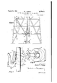
- Fig. 1 is an elevational view showing my invention applied to a conventionally illustrated oil well rig
- Fig. 2 is an enlarged, fragmentary plan view of the bushing-engaging element on the supporting arm;
- Fig. 3 is a section on line 33 of Fig. 2;
- Fig. 4 is a View similar to Fig. l but showing 21 variational embodiment of my invention
- Fig. 5 is a fragmentary top plan view of Fig. 4;
- Fig. 6 is a side elevation of Fig. 4;
- Fig. 7 is an enlarged section on line T-1 of Fig. 5 but showing the well pipe and suspension hook in elevation;
- Fig. 8 is a bottom plan view of Fig. 7;
- Fig, 9 is a view similar to Fig. 1 but showing a variational embodiment of the invention.
- Fig. 10 is a fragmentary top plan view of Fig. 9;
- Fig. 11 is an enlarged, fragmentary section on Fig. 12 is a section on line l2-l2 of Fig. 11.
- Fig. 1 I have illustrated an oil well rig in somewhat conventional form and as including a usual derrick I0, rotary table II, cat line and hook l2, and drill pipe I3, the latter extending axially through the bore of table II.
- the bushing may be of any suitable type, so long as it is of a construction which will allow it to be lifted bodily from the table without opening up to free it from its pipe-encircling condition. It is here shown as of one-piece construction which lends itself particularly well to application of my invention,
- Bushing I4 is illustrated as being provided with a detachable bail l1, and as having a major conical bore [8, an upper, square counterbore l9, and an upwardly and inwardly tapering lower bore 20 (Figs. 2 and 7).
- Kelly drive bushings and wedge slips are adapted to be interchangeably mounted in the master bushing bore, but since these elements are normally removed before application of my suspension means to the bushing, they are'not here illustrated.
- My bushing suspension means embodies a pair of arms 25 which are pivoted at their outer ends vided an integral bushing-engaging member 29 which is bent angularly from the arm and formed as hook 30, including offset portion'3l" and V-fork portion 32, the fork mouth 32' being in line with the arm axis.
- the hooks on the two arms are ofiset oppositely and their mouths" open oppositely, as clearly shown in Fig. 2.
- Arms 25 normally hang vertical-1y as illustrated in dotted lines in Fig. 1, where they are out of the way and yet in position to be immediately available when occasion for their use arises.
- Bushing I4 is then lowered until it rests upon and is supported by the upper faces of the two hook ends.
- the cat line may then-be discon-'-' nected and the bushing will be held' in-elevated position until occasion arises for returning the bushing to the table, when the operations de-' scribed above are reversed.
- 28 may be sufficiently loose", or otherwise suitably formed to allow sufficient bodily horizontal movement of thearm's to permit the described pipe-passing operations;
- a single bushing-engaging hook 30 is utilized.
- This hook opens upwardly and is carried rigidly by a pair of arms 25 which spread from the hook in the form of a V (Fig. 5) with their upper ends pivoted at 21' to brackets 26' at adjacent corners of the derrick.
- the hook has a hand-hold 46" while its n'ose has an external face 4
- the arm and hook normally occupy the"; dotted line positions of Fig. 6.
- Arm 25' is then swung inwardly and'upw'ardly to the full line position of Figs. 6 and 7 with face 4
- Figs. 9 to'1 2, inclusive I have shown a variation in which arms 25a and 25b are pivoted to brackets 26a at diagonally opposite corners of the derrick.
- the distal end of arm 25b is formed'as a bushing-engaging fork 50, the arms 5
- Keeper pin 53 has a hand hold"'55 and is'chained at 56 to fork 50 to prevent its misplacement or loss when the arm' 25b is hanging idly.
- bushin I4 is lowered on top of .fork arms 5
- a bushing support adapted to beassociated with an oil well rig includinga rotary table and a bushing" therefor, through the bore of which bushing a Vertical pi'peisadapted to extend, said support embodying a pair of armsadapted to-be mounted at opposite sides of" the table for pivotal movement about horizontal axes at"po'ints'- above the table, a pair of elements, one on the distal end of each arm, said arms being of individual lengths to swing their associated elements'into positions where at least one of them is in supporting engagement with said bushing when the latteri's lifted clear of the table and along the pipe to a predetermined height, and releasable means interconnecting the two elements toprevent their separation when they are so positioned'.
- a bushing supporting device embodying a pair of rods adapte'd to be pivotally mbunted' at opposite sides of and above a-rotary'table where; by' their distal ends are movable into and out of positions overlying the table, a fork on the distal end. of one rod, a portion on the distal end of the other rod adapted to enter the space between the arms of the fork when said ends are in said overlying position, and releasable means for holding said fork and portion against relative separative movement.
- a bushing supporting member embodying a rod, one end of which is adapted to be pivotally connected to a supporting structure at one side of and above a rotary table, the rod being movable pivotally to and from a position where its distal end overlies the table, and a fork rigid with the distal end of the rod and bent out of the axial plane of the rod to such extent that the fork is substantially horizontal when the rod is in said position; the mouth of the fork opening toward said one side when the rod-is in said position.
- a bushing support adapted to be associated with a well rig including a rotary table having a central bore and a bushing therefor, which bushing forms a fully encircling annulus about a well pipe extending vertically through the table bore; said support embodying a pivot memher which is mounted independently of the table at a point above and at one side thereof, a rigid arm' connected to said member for pivotal movement about a horizontal axis and substantially restrictively through a vertical plane which extends from said member towards said pipe, and a bushing engaging element rigidly connected to the distal end of the arm, said arm being adapted when in inoperative position, to hang clear of the table and bushing, the arm being of such length that, when pivotally swung to operative position through said vertical plane after the bushing is lifted out of the plane of the table and along the pipe to a predetermined height and with the bushing still fully encircling the pipe, said element is brought directly into en- 20 gagement with the bushing.
Landscapes
- Engineering & Computer Science (AREA)
- Life Sciences & Earth Sciences (AREA)
- Geology (AREA)
- Mining & Mineral Resources (AREA)
- Mechanical Engineering (AREA)
- Physics & Mathematics (AREA)
- Environmental & Geological Engineering (AREA)
- Fluid Mechanics (AREA)
- General Life Sciences & Earth Sciences (AREA)
- Geochemistry & Mineralogy (AREA)
- Supports For Pipes And Cables (AREA)
Description
March 10, 1942.
w. A ABEGG BUSHING SUPPORTING MEANS FOR OIL WELL RIGS Filed Oct. 5, 1939 4. Sheets-Sheet 1 a r M m gr ww March 10, 1942- w. A. ABEGG 2,275,313
BUSHING SUPPORTING MEANS FOR OIL WELL RIGS Filed Oct. 3, 1939 .4 Sheets-Sheet 2 uw- 27in f-l-IIJ I; I a
March 10, 1942. w. A. ABEGG BUSHING SUPPORTING MEANS FOR OIL WELL RIGS Filed Oct, 3, 1939 4 Sheets-Sheet 3 March 10, 1942. w A, ABEGG BUSHING SUPPORTING MEANS FOR OIL WELL RIGS 4- Sheets-Shet 4 Patented Mar. 10, 1942 BUSHING SUPPORTING MEANS FOR OIL WELL RIGS Walter A. Abegg, Los Angeles, Calif., assignor to Abegg & Reinhold Co.,'Ltd., Los Angeles, Calif., a corporation of California Application October 3, 1939, Serial No. 297,708
4 Claims. 255-1) This invention has to do generally with bushing supporting means for oil well rigs and is more particularly concerned with means whereby bushings for rotary tables may be supported above those tables without disturbing the pipe-encircling condition of the bushings.
While the bushing, to be supported as above, may be of any character, the invention is used to particular advantage in connection with table or master bushings, and I have therefore illustrated and will describe the invention as so embodied, but it will be understood this is not to be considered as limiting the invention, considered in its broader aspects.
In my copending application filed October 29, 1937, Rotary table bushing and means for handling same, Ser. No. 171,759, which issued December 19, 1939 as Patent No. 2,183,526, I have set forth in some detail the advantage of utilizing a one-piece table bushing and the occasion for lifting such a bushing clear of the table while the drill stem remains in its position of vertical extension through that table.
In said copending application, various means are shown for transferring the weight of the bushing to the pipe after said bushing has been lifted to a position of vertical clearance above the table.
It is among the objects of the present invention to provide a bushing support which is mounted on the drilling rig but normally clear of the table and associated parts, being quickly and easily movable into a position of bushing-support when occasion for such support arises. Once the bushing has been elevated to a given position of vertical clearance above the table, the supporting means is swung into supporting engagement with the bushing while the latter still encircles the pipe, and the driller may then proceed with whatever operation he has in mind without interference from the bushing and without fear that said bushing (which is normally decidedly bulky and heavy) may fall back to the table.
The support is of such character that the bushing does not have to be especially prepared or fabricated to take it. In its simplest form it may be applied to any standard bushing, and, in this connection, it is to be understood that while the invention is particularly well adapted for use with one-piece bushings, it is also decidedly useful in connection with bushings of the hingedsection type, where those sections are latched in encircling condition about the pipe and thereline ll--ll of Fig. 9; and
fore may be lifted and supported as a unit while still in such encircling condition.
Other objects and features of novelty will be made apparent in the following detailed descrip- 1 tion. Reference will be made to the accompanying drawings, wherein:
Fig. 1 is an elevational view showing my invention applied to a conventionally illustrated oil well rig;
Fig. 2 is an enlarged, fragmentary plan view of the bushing-engaging element on the supporting arm;
Fig. 3 is a section on line 33 of Fig. 2;
Fig. 4 is a View similar to Fig. l but showing 21 variational embodiment of my invention;
Fig. 5 is a fragmentary top plan view of Fig. 4; Fig. 6 is a side elevation of Fig. 4;
Fig. 7 is an enlarged section on line T-1 of Fig. 5 but showing the well pipe and suspension hook in elevation;
Fig. 8 is a bottom plan view of Fig. 7;
Fig, 9 is a view similar to Fig. 1 but showing a variational embodiment of the invention;
Fig. 10 is a fragmentary top plan view of Fig. 9;
Fig. 11 is an enlarged, fragmentary section on Fig. 12 is a section on line l2-l2 of Fig. 11. In Fig. 1 I have illustrated an oil well rig in somewhat conventional form and as including a usual derrick I0, rotary table II, cat line and hook l2, and drill pipe I3, the latter extending axially through the bore of table II.
,At I4 is illustrated a master bushing which normally occupies the table bore I6 and takes. pipe I3 within its own bore.
The bushing may be of any suitable type, so long as it is of a construction which will allow it to be lifted bodily from the table without opening up to free it from its pipe-encircling condition. It is here shown as of one-piece construction which lends itself particularly well to application of my invention,
but this showing is not to be considered as limitative on the broader aspects of the invention.
Bushing I4 is illustrated as being provided with a detachable bail l1, and as having a major conical bore [8, an upper, square counterbore l9, and an upwardly and inwardly tapering lower bore 20 (Figs. 2 and 7). Kelly drive bushings and wedge slips are adapted to be interchangeably mounted in the master bushing bore, but since these elements are normally removed before application of my suspension means to the bushing, they are'not here illustrated.
My bushing suspension means embodies a pair of arms 25 which are pivoted at their outer ends vided an integral bushing-engaging member 29 which is bent angularly from the arm and formed as hook 30, including offset portion'3l" and V-fork portion 32, the fork mouth 32' being in line with the arm axis. The hooks on the two arms are ofiset oppositely and their mouths" open oppositely, as clearly shown in Fig. 2.
When bushing I4 is to be clearedfr'om' table II', cat hook I2 is engaged with'bail I! and'operated to elevate the bushing to a position somewhat above that which it occupies in Fig. 1. Thereupon arms 25 are swung inwardly and upwardly. As they approach pipe l3 they are sprung horizontally to permit the hooks 3D" to pass the pipe. When the hooks are suificie'ntly high to allow noses 35 to clear thepipe, the arms are allowed to spring back to their normal condition, which brings each hook at the side'of the pipe remote from the pivotal mounting of the associated arm. When the arms are then lowered slightly, the hooks will engage the pipe as illustrated in Figs. 2 and 3'andthe pipe will, of course, prevent the arms from dropping further. Bushing I4 is then lowered until it rests upon and is supported by the upper faces of the two hook ends. The cat line may then-be discon-'-' nected and the bushing will be held' in-elevated position until occasion arises for returning the bushing to the table, when the operations de-' scribed above are reversed.
Of course, instead of springing the arms to allow the hooks to pass the pipe, the pin'an'd. eye connections 2'|28 may be sufficiently loose", or otherwise suitably formed to allow sufficient bodily horizontal movement of thearm's to permit the described pipe-passing operations;
In Figs. 4 to 8, inclusive, I have shown a Varia tional embodiment of the invention wherein a single bushing-engaging hook 30 is utilized. This hook opens upwardly and is carried rigidly by a pair of arms 25 which spread from the hook in the form of a V (Fig. 5) with their upper ends pivoted at 21' to brackets 26' at adjacent corners of the derrick.
The hook has a hand-hold 46" while its n'ose has an external face 4| which extendsvertically along the pipe and is a'rcuately formed to fit the curvature of the pipe periphery, all when the hook is in the position of Fig. '7. 7 a A The arm and hook normally occupy the"; dotted line positions of Fig. 6. When the bushing I4 is to be suspended, it is lifted along the pipe as described in connection with l to' a position slightly above that illustrated in Fig. 6.-
Arm 25' is then swung inwardly and'upw'ardly to the full line position of Figs. 6 and 7 with face 4| in engagement with the pipe. 43 of the hook nose is inclined with respect to face 4|, these two faces definingwhat maybe termed a wedge nose 44 on the end of the hook.
With the hook manually held iri the above" The inner faceposition, bushing I4 is lowered onto the hook, the wedge nose 44 entering bushing bore 20 or, expressed otherwise, the annular clearance space between the bushing and pipe l3.
As the cat line is slacked off, the bushing will tilt into the position of Fig. 6. Thereafter the bushing will prevent the outward swinging of the arm and hook and since the hook cannot drop without coincidentally swinging outward, said hook will remain in the position of Fig. 6 and, through arms 25', support the bushing in its predetermined position of elevation above the rotary table until occasion arises to return the bushing to the table, when the above operations will be reversed.
In Figs. 9 to'1 2, inclusive, I have shown a variation in which arms 25a and 25b are pivoted to brackets 26a at diagonally opposite corners of the derrick. The distal end of arm 25b is formed'as a bushing-engaging fork 50, the arms 5| of which are sufficiently spread to take pipev and'inwardly to the positions of Figs. 11 and 12,-
with eye 52 entered between fork arm's 51. A keeper pin 53 is then' thrust through eye 52 and suitable apertures 54 in fork arms5l, to hold the fork and eye against relative separative movement and thus holding the entire su.spens'iori unit in the condition'of Figs. 11 and 12. Keeper pin 53 has a hand hold"'55 and is'chained at 56 to fork 50 to prevent its misplacement or loss when the arm' 25b is hanging idly.
With the suspension arms thus coupled to gether and prevented from swinging downwardly and outwardly, bushin I4 is lowered on top of .fork arms 5| and thus maintainedina predetermined position of elevation above the rotary table'until occasion' arises for returning-the'bushing to the table, when the above operations are reversed.
While I have illustrated and described preferred embodiments of my invention; various changes in design, structure and' arrangement may be made without departing from the spirit and scope of the appended claims.
I claim:
1. A bushing support adapted to beassociated with an oil well rig includinga rotary table and a bushing" therefor, through the bore of which bushing a Vertical pi'peisadapted to extend, said support embodying a pair of armsadapted to-be mounted at opposite sides of" the table for pivotal movement about horizontal axes at"po'ints'- above the table, a pair of elements, one on the distal end of each arm, said arms being of individual lengths to swing their associated elements'into positions where at least one of them is in supporting engagement with said bushing when the latteri's lifted clear of the table and along the pipe to a predetermined height, and releasable means interconnecting the two elements toprevent their separation when they are so positioned'.
2. A bushing supporting device embodying a pair of rods adapte'd to be pivotally mbunted' at opposite sides of and above a-rotary'table where; by' their distal ends are movable into and out of positions overlying the table, a fork on the distal end. of one rod, a portion on the distal end of the other rod adapted to enter the space between the arms of the fork when said ends are in said overlying position, and releasable means for holding said fork and portion against relative separative movement.
3. A bushing supporting member embodying a rod, one end of which is adapted to be pivotally connected to a supporting structure at one side of and above a rotary table, the rod being movable pivotally to and from a position where its distal end overlies the table, and a fork rigid with the distal end of the rod and bent out of the axial plane of the rod to such extent that the fork is substantially horizontal when the rod is in said position; the mouth of the fork opening toward said one side when the rod-is in said position.
4. A bushing support adapted to be associated with a well rig including a rotary table having a central bore and a bushing therefor, which bushing forms a fully encircling annulus about a well pipe extending vertically through the table bore; said support embodying a pivot memher which is mounted independently of the table at a point above and at one side thereof, a rigid arm' connected to said member for pivotal movement about a horizontal axis and substantially restrictively through a vertical plane which extends from said member towards said pipe, and a bushing engaging element rigidly connected to the distal end of the arm, said arm being adapted when in inoperative position, to hang clear of the table and bushing, the arm being of such length that, when pivotally swung to operative position through said vertical plane after the bushing is lifted out of the plane of the table and along the pipe to a predetermined height and with the bushing still fully encircling the pipe, said element is brought directly into en- 20 gagement with the bushing.
WALTER A. ABEGG.
Priority Applications (1)
| Application Number | Priority Date | Filing Date | Title |
|---|---|---|---|
| US297708A US2275813A (en) | 1939-10-03 | 1939-10-03 | Bushing supporting means for oil well rigs |
Applications Claiming Priority (1)
| Application Number | Priority Date | Filing Date | Title |
|---|---|---|---|
| US297708A US2275813A (en) | 1939-10-03 | 1939-10-03 | Bushing supporting means for oil well rigs |
Publications (1)
| Publication Number | Publication Date |
|---|---|
| US2275813A true US2275813A (en) | 1942-03-10 |
Family
ID=23147413
Family Applications (1)
| Application Number | Title | Priority Date | Filing Date |
|---|---|---|---|
| US297708A Expired - Lifetime US2275813A (en) | 1939-10-03 | 1939-10-03 | Bushing supporting means for oil well rigs |
Country Status (1)
| Country | Link |
|---|---|
| US (1) | US2275813A (en) |
Cited By (2)
| Publication number | Priority date | Publication date | Assignee | Title |
|---|---|---|---|---|
| US2540451A (en) * | 1946-04-13 | 1951-02-06 | Benjamin F Kelley | Pipe aligning device |
| US3026950A (en) * | 1958-02-28 | 1962-03-27 | John H Johnson | Apparatus for boring holes |
-
1939
- 1939-10-03 US US297708A patent/US2275813A/en not_active Expired - Lifetime
Cited By (2)
| Publication number | Priority date | Publication date | Assignee | Title |
|---|---|---|---|---|
| US2540451A (en) * | 1946-04-13 | 1951-02-06 | Benjamin F Kelley | Pipe aligning device |
| US3026950A (en) * | 1958-02-28 | 1962-03-27 | John H Johnson | Apparatus for boring holes |
Similar Documents
| Publication | Publication Date | Title |
|---|---|---|
| US2410589A (en) | Automatic slip mechanism | |
| US3857450A (en) | Drilling apparatus | |
| CA2448841C (en) | Pipe handling device, method and system | |
| US7770654B2 (en) | Pipe handling device, method and system | |
| CA2340994C (en) | Method and apparatus for connecting tubulars using a top drive | |
| US4209066A (en) | Method and apparatus for running tubular goods into and out of a borehole | |
| US3629927A (en) | Mouse hole chuck | |
| US3351372A (en) | Split hook hoisting apparatus | |
| CN204984308U (en) | Automatic cat way device of workover rig | |
| US1967517A (en) | Method and apparatus for handling pipe in wells | |
| US1656864A (en) | Pipe holder | |
| US3785690A (en) | Tool for use in removing a fish stuck within a well bore | |
| US2275813A (en) | Bushing supporting means for oil well rigs | |
| US2575649A (en) | Automatic drill slip unit | |
| US2054223A (en) | Well drilling system | |
| US1825018A (en) | Rotary and casing hook | |
| US2271578A (en) | Collapsible mast erection | |
| US2662737A (en) | Automatic control of slips of drill pipe strings of sounding holes | |
| US2300370A (en) | Sucker rod elevator | |
| US2636241A (en) | Power-operated slip | |
| CN101688431A (en) | Top drive equipment and its lifting ring | |
| US1454194A (en) | Elevator | |
| US2572318A (en) | Pipe holding slip | |
| US3588162A (en) | Rotating flapper elevator | |
| US1983545A (en) | Rotary well drilling apparatus |