US2274519A - Hydraulic cylinder construction - Google Patents
Hydraulic cylinder construction Download PDFInfo
- Publication number
- US2274519A US2274519A US284522A US28452239A US2274519A US 2274519 A US2274519 A US 2274519A US 284522 A US284522 A US 284522A US 28452239 A US28452239 A US 28452239A US 2274519 A US2274519 A US 2274519A
- Authority
- US
- United States
- Prior art keywords
- strips
- cylinder
- plate
- wall
- welding
- Prior art date
- Legal status (The legal status is an assumption and is not a legal conclusion. Google has not performed a legal analysis and makes no representation as to the accuracy of the status listed.)
- Expired - Lifetime
Links
Images
Classifications
-
- F—MECHANICAL ENGINEERING; LIGHTING; HEATING; WEAPONS; BLASTING
- F16—ENGINEERING ELEMENTS AND UNITS; GENERAL MEASURES FOR PRODUCING AND MAINTAINING EFFECTIVE FUNCTIONING OF MACHINES OR INSTALLATIONS; THERMAL INSULATION IN GENERAL
- F16L—PIPES; JOINTS OR FITTINGS FOR PIPES; SUPPORTS FOR PIPES, CABLES OR PROTECTIVE TUBING; MEANS FOR THERMAL INSULATION IN GENERAL
- F16L9/00—Rigid pipes
- F16L9/18—Double-walled pipes; Multi-channel pipes or pipe assemblies
-
- B—PERFORMING OPERATIONS; TRANSPORTING
- B21—MECHANICAL METAL-WORKING WITHOUT ESSENTIALLY REMOVING MATERIAL; PUNCHING METAL
- B21C—MANUFACTURE OF METAL SHEETS, WIRE, RODS, TUBES OR PROFILES, OTHERWISE THAN BY ROLLING; AUXILIARY OPERATIONS USED IN CONNECTION WITH METAL-WORKING WITHOUT ESSENTIALLY REMOVING MATERIAL
- B21C37/00—Manufacture of metal sheets, bars, wire, tubes or like semi-manufactured products, not otherwise provided for; Manufacture of tubes of special shape
- B21C37/06—Manufacture of metal sheets, bars, wire, tubes or like semi-manufactured products, not otherwise provided for; Manufacture of tubes of special shape of tubes or metal hoses; Combined procedures for making tubes, e.g. for making multi-wall tubes
- B21C37/08—Making tubes with welded or soldered seams
- B21C37/09—Making tubes with welded or soldered seams of coated strip material ; Making multi-wall tubes
-
- Y—GENERAL TAGGING OF NEW TECHNOLOGICAL DEVELOPMENTS; GENERAL TAGGING OF CROSS-SECTIONAL TECHNOLOGIES SPANNING OVER SEVERAL SECTIONS OF THE IPC; TECHNICAL SUBJECTS COVERED BY FORMER USPC CROSS-REFERENCE ART COLLECTIONS [XRACs] AND DIGESTS
- Y10—TECHNICAL SUBJECTS COVERED BY FORMER USPC
- Y10T—TECHNICAL SUBJECTS COVERED BY FORMER US CLASSIFICATION
- Y10T29/00—Metal working
- Y10T29/49—Method of mechanical manufacture
- Y10T29/49229—Prime mover or fluid pump making
- Y10T29/49236—Fluid pump or compressor making
-
- Y—GENERAL TAGGING OF NEW TECHNOLOGICAL DEVELOPMENTS; GENERAL TAGGING OF CROSS-SECTIONAL TECHNOLOGIES SPANNING OVER SEVERAL SECTIONS OF THE IPC; TECHNICAL SUBJECTS COVERED BY FORMER USPC CROSS-REFERENCE ART COLLECTIONS [XRACs] AND DIGESTS
- Y10—TECHNICAL SUBJECTS COVERED BY FORMER USPC
- Y10T—TECHNICAL SUBJECTS COVERED BY FORMER US CLASSIFICATION
- Y10T29/00—Metal working
- Y10T29/49—Method of mechanical manufacture
- Y10T29/49229—Prime mover or fluid pump making
- Y10T29/4927—Cylinder, cylinder head or engine valve sleeve making
-
- Y—GENERAL TAGGING OF NEW TECHNOLOGICAL DEVELOPMENTS; GENERAL TAGGING OF CROSS-SECTIONAL TECHNOLOGIES SPANNING OVER SEVERAL SECTIONS OF THE IPC; TECHNICAL SUBJECTS COVERED BY FORMER USPC CROSS-REFERENCE ART COLLECTIONS [XRACs] AND DIGESTS
- Y10—TECHNICAL SUBJECTS COVERED BY FORMER USPC
- Y10T—TECHNICAL SUBJECTS COVERED BY FORMER US CLASSIFICATION
- Y10T29/00—Metal working
- Y10T29/49—Method of mechanical manufacture
- Y10T29/49826—Assembling or joining
- Y10T29/49879—Spaced wall tube or receptacle
Definitions
- This invention relates to 'the construction of double walled hydraulic cylinders.
- the main objects of this invention are to provide an improved method and process for fabricating a double walled hydraulic cylinder, and to-provide a construction of double Walled hydraulic cylinder of materially lower cost tha has heretofore been possible.
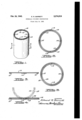
- Fig. l is a fragmentary view ln perspective of a double walled cylinder formed in accordance with this invention.
- Fig. 2 is a sectional view taken on the line 2-2 of Fig. 1 looking in the direction indicated by the arrows.
- FIG. 3 is an edge sectional view of one of the 1 plates from which the cylinder is formed during the rst step of its fabrication, and showing spacer strips welded thereto;
- Fig. 4 is a similar view showing two plates one interposed upon the other in full lines and in dotted lines the form givento the two plates during a further step of fabrication;
- Fig. 5 is a' sectional view of a modified form of a double walled cylinder in which the inner cylinder is seamless.
- the hydraulic jacks be of what is generally known as the telescoping type and which employ the double walled pistons in order to vent the fluid back to the low pressure side of the hydraulic pump when the multiple pistons have been extended to a predetermined point.
- the double walled cylinder is formed from flat rolled rectangular shaped plates, that is to say, from standard rolling stock.
- a plate Illof suitable vdimensions and preferably rectangular in shape has three spacer strips I2, I4 and I6 'welded thereto. 'I'he strips I2 and I6 being positioned along opposite marginal edges, and the strip I4 being secured along substantially the medial portion of the plate. These strips are preferably of the same lengthvas the plate I0, although a series of spaced strips of shorter length may be used with spaces between, if desired.
- the inner and outer surfaces at the points of weld may be ground off iiush with the inner and outer surfaces of the tubes, which operation is readily done and relatively inexpensive.
- the inner wall of the double walled cylinder is formed of a length of seamless steel tubing to which is welded two plates of the kind shown in Fig. 3. That is to say, two plates, such as shown in Fig. 3, after having the spacing strips I2, I4 and I6 welded thereto, are then formed in semi-cylindrical shape, and two of such semi-cylindrical shells are abutted edge to edge and welded to each other and to the inner seamless steel tubing 20.
- the spacer strips I2, I4 or I6 are of continuous character and extend the full length of the cylinder, or are of shorter length with spaces therebetween. Suitable capacity may be provided between the inner and outer cylinder walls by varying the thickness of these spacer strips, and by varying their width so that ample communication for the passage of fluid may be had depending upon the requirement of the particular installation.
- a tube such as shown in Fig. 2 of the drawing, may be made entirely from rolled flat strip stock, and with verylittle forming and a minimum of machining to iinish the job, a double walled cylinder may be constructed of relatively low cost materials and with low cost of fabrication. The result is a double walled cylinder having a total low cost, and which compares in cost most favorably with a single wall seamless steel tube.
- me cost is slightly greater due to the fact that the inner wall comprises a seamless steel tube which is of relatively greater cost in the first instance.
- rolled plate stock is extremely accuratel as to dimension of thickness with the result rthat when the double walled cylinder is formed, as in Fig. 2, concentricity is automatically secured betweei the inner wall of the inner tube and the outer wall of the outer tube which thereby eliminates expensive machine -work to secure the necessary concentricity between these inner and outer wall surfaces.
- This is an extremely advantageous feature of utilizing rolled stock which is of very uniform and precise thickness throughout its length and breadth so that cylinders of substantial length may be made by this method, and which are truly concentric as to their inner and outer wall surfaces with a minimum of machine work.
- the method of forming a double wall cylinder which comprises the welding of longitudinally extending spacer strips to one side of a rectangular metal plate, superimposing a second rectangular metal plate upon said rst plate in contact with said spacer strips, providing a free space between said plates, welding said second plate to at least one of said strips, forming said attached plates into a semi-cylindrical double wall shell, welding said second platev to the other of said spacer strips, placing two such shells with their axially extending edges in abutting relation and welding said abutting edges to form a double wall cylinder.
- the method of forming a double wall cylinder which comprises the welding of at least three longitudinally extending spacer strips to one side of a rectangular metal plate, one of said strips being positioned substantially along the longitudinal center line and the other two strips being positioned adjacent the longitudinal edges of said plate, superimposing a second rectangular plate upon said first plate in contact with said strips, providing a free space between saidplates, welding said second plate to the medial spacer strip, forming said attached strips into a semi-cylindrical double wall shell, welding said second plate to the other' of said spacer strips, placing two such shells with their axially extending edges in abutting relation and then welding said abutting edges to form a double wall cylinder.
- the method of forming a double wall cylinder which comprises the welding of at least three longitudinally extending spacer strips to one side of a rectangular metal plate, one of said strips being positioned substantially along the longitudinal center line and the other two strips being positioned adjacent. the longitudinal edges of said plate, superimposing a second rectangular plate of slightly different width upon said first plate in contact with said strips, providing a free space between said plates, welding said second plate to the medial spacer strip, forming said attached strips. into a semi-cylindrical double wall shell, welding said second plate to the other of said spacer strips, placing two such shells with their axially extending edges in abutting relation and then welding said abutting edges to form a double wall cylinder.
Landscapes
- Engineering & Computer Science (AREA)
- Mechanical Engineering (AREA)
- General Engineering & Computer Science (AREA)
Description
Feb- 24, 1942 E. R. BARRETT HYDRAULIC CYLINDER CONSTRUCTION Filed July 14, 1939 l IN VENTOR Mr; Edf/eff BY M4/d Vm@ TToRNE Ys.
Patented Feb. 24, 1942 u NlTl-:D STATE HYDRAULIC CYLINDER cous:rrwc'rroNI Edward RfBarrett, Detroit, Mich., asslgnor to Gar Wood Industries, Inc., Detroit, Mich., a
corporation of Michigan Application July 14, 1939, serial No. 284,522
' 4 claims. (ci. 29,456.4) t
This invention relates to 'the construction of double walled hydraulic cylinders.
The main objects of this invention are to provide an improved method and process for fabricating a double walled hydraulic cylinder, and to-provide a construction of double Walled hydraulic cylinder of materially lower cost tha has heretofore been possible.
An illustrative embodiment of this invention is shown in the accompanying drawing, in which: v
Fig. l is a fragmentary view ln perspective of a double walled cylinder formed in accordance with this invention;
Fig. 2 is a sectional view taken on the line 2-2 of Fig. 1 looking in the direction indicated by the arrows.
thermore, the space between thetwo tubes will 4vary to a great extent due to the varying thick-` ness of the tube walls. Furthermore, seamless steel tubing made with any reasonable degree Fig. 3 is an edge sectional view of one of the 1 plates from which the cylinder is formed during the rst step of its fabrication, and showing spacer strips welded thereto;
Fig. 4 is a similar view showing two plates one interposed upon the other in full lines and in dotted lines the form givento the two plates during a further step of fabrication; and,
Fig. 5 is a' sectional view of a modified form of a double walled cylinder in which the inner cylinder is seamless. l
In certain arts and industries, such as in the manufacture of hydraulic jacks, it is some times desirable to fabricate and provide a cylinder used as a piston which is of double walled construction with'a space between the walls which provides a fluid passageway so that fluid may be conducted fromr one end of the cylinder or piston to the other through this inner passageway.
,'ferent wall thickness. This is true, of course,
of both the inner and outer tubes, and when placed together, it is extremely diicult to have the outer wall of the outer tube concentric to the inner wall of the inner tube without a very considerable amount of .machine work beingdone on the inner or outer surfaces, or both. Furof accuracy is relatively expensive with the result that when a double wall hydraulic piston is made from two seamless steel tubes which '1n and of themselves are expensive in the first instance, and then added to that the cost of considerable machining to bring their respective in-y ner and outer surfaces into concentricity, the result is that the finished article is very high priced as compared to asingle wall piston.
The high cost of manufacture of double walled pistons when made from two seamless steel tubes has been a lbig obstacle and drawback to the` utilization of hydraulic jacks employing double wall piston, and in some instances the cost has been really prohibitive from a commercial standpoint.
On the other hand, there are certain installations of hydraulic jacks, particularly in connection with some types of motor truck dump bodies,`
wherein it is most desirable and nearly necessary that the hydraulic jacks be of what is generally known as the telescoping type and which employ the double walled pistons in order to vent the fluid back to the low pressure side of the hydraulic pump when the multiple pistons have been extended to a predetermined point.
It is understood, of course, that in the use of hydraulic jacks of this character, it is customary for the operator to start the hydraulic pump and turn his valve so that the uid under pressure is delivered to the hydraulic jacks and that it would be extremely difficult and well nigh impossible for him to shut off the pump at the exact moment the pistons reach their fully extended position. Some pumps, of course, have been provided with by-passes so that when pressures reach a certain determined amount, the uid will not wreck the hydraulic system, but will be by-passed within the pump, but this means that the pressures must go up to an extremely high point, otherwise the pumps will not perform their desired function when the truck bodies are heavily loaded. The usual and desirable Way to have this arranged is for the hydraulic jacks to uncover a passageway when they have extended to a predeterminedrpoint which will allow the uid toy flow back into the low pressure side of the system.
In Figs. 1, 2 and 4 of the drawing, the double walled cylinder is formed from flat rolled rectangular shaped plates, that is to say, from standard rolling stock. A plate Illof suitable vdimensions and preferably rectangular in shape has three spacer strips I2, I4 and I6 'welded thereto. 'I'he strips I2 and I6 being positioned along opposite marginal edges, and the strip I4 being secured along substantially the medial portion of the plate. These strips are preferably of the same lengthvas the plate I0, although a series of spaced strips of shorter length may be used with spaces between, if desired.
side edges are substantially radial with respect to the center of curvature, and at this time the opposite marginal edges of the plate I8 may be welded to the spacer strips I2 and I6.
Two such formed shells are then abutted with their axial side edges in registry, as shown in Fig. 2 of the drawing, at which time they are welded together, thereby forming a double wall cylinder with axially extending spaces between the walls thereof. In instances where the spacing strips are of extremely short length, the space between the two walls is substantially angular and continuous except for the slight interruptions of the spacer locks.
After the two semi-cylindrical shells have been welded together to form a complete double walled cylinder, then the inner and outer surfaces at the points of weld may be ground off iiush with the inner and outer surfaces of the tubes, which operation is readily done and relatively inexpensive.
In the modification shown in Fig. of the drawing the inner wall of the double walled cylinder is formed of a length of seamless steel tubing to which is welded two plates of the kind shown in Fig. 3. That is to say, two plates, such as shown in Fig. 3, after having the spacing strips I2, I4 and I6 welded thereto, are then formed in semi-cylindrical shape, and two of such semi-cylindrical shells are abutted edge to edge and welded to each other and to the inner seamless steel tubing 20.
In the use of double wall cylinders in hydraulic systems of this character, it is immaterial Whether the spacer strips I2, I4 or I6 are of continuous character and extend the full length of the cylinder, or are of shorter length with spaces therebetween. Suitable capacity may be provided between the inner and outer cylinder walls by varying the thickness of these spacer strips, and by varying their width so that ample communication for the passage of fluid may be had depending upon the requirement of the particular installation.
As will be readily seen from the foregoing, a tube such as shown in Fig. 2 of the drawing, may be made entirely from rolled flat strip stock, and with verylittle forming and a minimum of machining to iinish the job, a double walled cylinder may be constructed of relatively low cost materials and with low cost of fabrication. The result is a double walled cylinder having a total low cost, and which compares in cost most favorably with a single wall seamless steel tube.
m the modification shown 1n Fig. 5, me cost is slightly greater due to the fact that the inner wall comprises a seamless steel tube which is of relatively greater cost in the first instance.
One`of the important advantages secured by utilizing the present invention is that rolled plate stock is extremely accuratel as to dimension of thickness with the result rthat when the double walled cylinder is formed, as in Fig. 2, concentricity is automatically secured betweei the inner wall of the inner tube and the outer wall of the outer tube which thereby eliminates expensive machine -work to secure the necessary concentricity between these inner and outer wall surfaces. This is an extremely advantageous feature of utilizing rolled stock which is of very uniform and precise thickness throughout its length and breadth so that cylinders of substantial length may be made by this method, and which are truly concentric as to their inner and outer wall surfaces with a minimum of machine work.
Although but two specific embodiments of the present invention have been described, it will be appreciated that Various changes in the form, number and arrangement of parts may be made within the spirit and scope thereof.
What is claimed is:
l. The method of forming a double wall cylinder which comprises the welding of longitudinally extending spacer strips to one side of a rectangular metal plate, superimposing a second rectangular metal plate upon said rst plate in contact with said spacer strips, providing a free space between said plates, welding said second plate to at least one of said strips, forming said attached plates into a semi-cylindrical double wall shell, welding said second platev to the other of said spacer strips, placing two such shells with their axially extending edges in abutting relation and welding said abutting edges to form a double wall cylinder.`
2. The method of forming a double wall cylinder which comprises the welding of at least three longitudinally extending spacer strips to one side of a rectangular metal plate, one of said strips being positioned substantially along the longitudinal center line and the other two strips being positioned adjacent the longitudinal edges of said plate, superimposing a second rectangular plate upon said first plate in contact with said strips, providing a free space between saidplates, welding said second plate to the medial spacer strip, forming said attached strips into a semi-cylindrical double wall shell, welding said second plate to the other' of said spacer strips, placing two such shells with their axially extending edges in abutting relation and then welding said abutting edges to form a double wall cylinder.
3. The method of forming a double wall cylinder which comprises the welding of at least three longitudinally extending spacer strips to one side of a rectangular metal plate, one of said strips being positioned substantially along the longitudinal center line and the other two strips being positioned adjacent. the longitudinal edges of said plate, superimposing a second rectangular plate of slightly different width upon said first plate in contact with said strips, providing a free space between said plates, welding said second plate to the medial spacer strip, forming said attached strips. into a semi-cylindrical double wall shell, welding said second plate to the other of said spacer strips, placing two such shells with their axially extending edges in abutting relation and then welding said abutting edges to form a double wall cylinder.
4. The method of forming a double wall cyl-v inder which comprises the welding of spacer '5 pieces to a plate, placing another plate upon said spacer pieces and welding said second plate to at least one of said spacer pieces, providing a free EDWARD R. BARRETT.
Priority Applications (1)
| Application Number | Priority Date | Filing Date | Title |
|---|---|---|---|
| US284522A US2274519A (en) | 1939-07-14 | 1939-07-14 | Hydraulic cylinder construction |
Applications Claiming Priority (1)
| Application Number | Priority Date | Filing Date | Title |
|---|---|---|---|
| US284522A US2274519A (en) | 1939-07-14 | 1939-07-14 | Hydraulic cylinder construction |
Publications (1)
| Publication Number | Publication Date |
|---|---|
| US2274519A true US2274519A (en) | 1942-02-24 |
Family
ID=23090512
Family Applications (1)
| Application Number | Title | Priority Date | Filing Date |
|---|---|---|---|
| US284522A Expired - Lifetime US2274519A (en) | 1939-07-14 | 1939-07-14 | Hydraulic cylinder construction |
Country Status (1)
| Country | Link |
|---|---|
| US (1) | US2274519A (en) |
Cited By (15)
| Publication number | Priority date | Publication date | Assignee | Title |
|---|---|---|---|---|
| US2467867A (en) * | 1944-09-11 | 1949-04-19 | Gen Electric | Electromagnetic induction apparatus and method of forming same |
| US2675284A (en) * | 1950-07-10 | 1954-04-13 | Brown Brothers & Co Ltd | Construction of rigid slotted cylinders |
| US2735502A (en) * | 1952-10-17 | 1956-02-21 | Hydraulic power steering with valved | |
| US2761425A (en) * | 1952-06-17 | 1956-09-04 | Gen Motors Corp | Reciprocatory fluid actuated device |
| US3191853A (en) * | 1964-11-16 | 1965-06-29 | Worthington Corp | Rotary compressor |
| US3193919A (en) * | 1961-05-26 | 1965-07-13 | Jr Thomas P M Rouse | Method of fabricating pressure vessels |
| US3960343A (en) * | 1974-10-29 | 1976-06-01 | Ssp Products, Inc. | Double wall ducting |
| FR2561142A1 (en) * | 1984-03-16 | 1985-09-20 | Ugine Gueugnon Sa | DOUBLE-WELD SOLDER TUBE AND METHOD OF MANUFACTURING THE SAME |
| US4590652A (en) * | 1983-10-14 | 1986-05-27 | Apx Group Inc. | Method for fabricating an air gap pipe |
| US4656713A (en) * | 1985-10-24 | 1987-04-14 | Ap Industries, Inc. | Method for forming an air gap pipe |
| US4712642A (en) * | 1986-02-11 | 1987-12-15 | Titeflex Corporation | Self-damping convoluted conduit |
| US4793384A (en) * | 1986-02-11 | 1988-12-27 | Titeflex Corporation | Self-damping convoluted conduit |
| US4867269A (en) * | 1987-06-30 | 1989-09-19 | Titeflex Corporation | Tuned self-damping convoluted conduit |
| US20100300574A1 (en) * | 2007-11-29 | 2010-12-02 | Yutaka Jinnouchi | Multiwall steel tube |
| US20100326694A1 (en) * | 2009-06-24 | 2010-12-30 | Baker Hughes Incorporated | Long length electro coiled tubing and method of manufacturing same |
-
1939
- 1939-07-14 US US284522A patent/US2274519A/en not_active Expired - Lifetime
Cited By (17)
| Publication number | Priority date | Publication date | Assignee | Title |
|---|---|---|---|---|
| US2467867A (en) * | 1944-09-11 | 1949-04-19 | Gen Electric | Electromagnetic induction apparatus and method of forming same |
| US2675284A (en) * | 1950-07-10 | 1954-04-13 | Brown Brothers & Co Ltd | Construction of rigid slotted cylinders |
| US2761425A (en) * | 1952-06-17 | 1956-09-04 | Gen Motors Corp | Reciprocatory fluid actuated device |
| US2735502A (en) * | 1952-10-17 | 1956-02-21 | Hydraulic power steering with valved | |
| US3193919A (en) * | 1961-05-26 | 1965-07-13 | Jr Thomas P M Rouse | Method of fabricating pressure vessels |
| US3191853A (en) * | 1964-11-16 | 1965-06-29 | Worthington Corp | Rotary compressor |
| US3960343A (en) * | 1974-10-29 | 1976-06-01 | Ssp Products, Inc. | Double wall ducting |
| US4590652A (en) * | 1983-10-14 | 1986-05-27 | Apx Group Inc. | Method for fabricating an air gap pipe |
| EP0156711A1 (en) * | 1984-03-16 | 1985-10-02 | Ugine Aciers De Chatillon Et Gueugnon | Welded double-walled tube and method for its manufacture |
| FR2561142A1 (en) * | 1984-03-16 | 1985-09-20 | Ugine Gueugnon Sa | DOUBLE-WELD SOLDER TUBE AND METHOD OF MANUFACTURING THE SAME |
| US4674542A (en) * | 1984-03-16 | 1987-06-23 | Ugine Gueugnon S.A. | Double-wall welded tube |
| US4656713A (en) * | 1985-10-24 | 1987-04-14 | Ap Industries, Inc. | Method for forming an air gap pipe |
| US4712642A (en) * | 1986-02-11 | 1987-12-15 | Titeflex Corporation | Self-damping convoluted conduit |
| US4793384A (en) * | 1986-02-11 | 1988-12-27 | Titeflex Corporation | Self-damping convoluted conduit |
| US4867269A (en) * | 1987-06-30 | 1989-09-19 | Titeflex Corporation | Tuned self-damping convoluted conduit |
| US20100300574A1 (en) * | 2007-11-29 | 2010-12-02 | Yutaka Jinnouchi | Multiwall steel tube |
| US20100326694A1 (en) * | 2009-06-24 | 2010-12-30 | Baker Hughes Incorporated | Long length electro coiled tubing and method of manufacturing same |
Similar Documents
| Publication | Publication Date | Title |
|---|---|---|
| US2274519A (en) | Hydraulic cylinder construction | |
| US2845695A (en) | Method of making refrigerating tubing | |
| US3256669A (en) | Sandwich panel | |
| US3807009A (en) | Method of manufacturing curved tube sections and the like | |
| DE102012211241B4 (en) | Forming tool for hot forming | |
| Windenburg et al. | Collapse by instability of thin cylindrical shells under external pressure | |
| US2759246A (en) | Method of making hollow articles | |
| JPH0686803B2 (en) | CAM SHAFT, ASSEMBLY METHOD AND ASSEMBLY DEVICE | |
| US2467668A (en) | Mandrel for expanding internallyfinned tubes | |
| EP2110189A1 (en) | Method for dieless forming of sheet metal | |
| US3068562A (en) | Method of making pressure vessels | |
| US3907371A (en) | Drop center truck rim and method of forming same | |
| US3297082A (en) | Heat exchangers of hollow construction | |
| US4122701A (en) | Collar sleeves and process and tool for the manufacture thereof | |
| US2683928A (en) | Method of corrugating tubing | |
| US3202467A (en) | Thin-walled cages for cylindrical rollers | |
| US2842284A (en) | Cylinder end seal for fluid pressure cylinder | |
| US3094147A (en) | Bendable tubing | |
| US2260221A (en) | Duct joint construction | |
| US3586544A (en) | Method of producing piston rings | |
| US2235070A (en) | Cylinder construction | |
| DE4126017A1 (en) | BRAKE CYLINDER AND METHOD FOR THE PRODUCTION THEREOF | |
| US2883744A (en) | Method of cold working a tubular structure | |
| US2994946A (en) | Deep drawn heat exchanger | |
| US2858115A (en) | Finned tubing |