US2266889A - Cutter relieving means for shaping machines - Google Patents
Cutter relieving means for shaping machines Download PDFInfo
- Publication number
- US2266889A US2266889A US299620A US29962039A US2266889A US 2266889 A US2266889 A US 2266889A US 299620 A US299620 A US 299620A US 29962039 A US29962039 A US 29962039A US 2266889 A US2266889 A US 2266889A
- Authority
- US
- United States
- Prior art keywords
- spindle
- cutter
- holder
- work
- axis
- Prior art date
- Legal status (The legal status is an assumption and is not a legal conclusion. Google has not performed a legal analysis and makes no representation as to the accuracy of the status listed.)
- Expired - Lifetime
Links
Images

Classifications
-
- B—PERFORMING OPERATIONS; TRANSPORTING
- B23—MACHINE TOOLS; METAL-WORKING NOT OTHERWISE PROVIDED FOR
- B23F—MAKING GEARS OR TOOTHED RACKS
- B23F23/00—Accessories or equipment combined with or arranged in, or specially designed to form part of, gear-cutting machines
- B23F23/12—Other devices, e.g. tool holders; Checking devices for controlling workpieces in machines for manufacturing gear teeth
- B23F23/1237—Tool holders
- B23F23/1287—Pinion shaper cutter holders
-
- Y—GENERAL TAGGING OF NEW TECHNOLOGICAL DEVELOPMENTS; GENERAL TAGGING OF CROSS-SECTIONAL TECHNOLOGIES SPANNING OVER SEVERAL SECTIONS OF THE IPC; TECHNICAL SUBJECTS COVERED BY FORMER USPC CROSS-REFERENCE ART COLLECTIONS [XRACs] AND DIGESTS
- Y10—TECHNICAL SUBJECTS COVERED BY FORMER USPC
- Y10T—TECHNICAL SUBJECTS COVERED BY FORMER US CLASSIFICATION
- Y10T409/00—Gear cutting, milling, or planing
- Y10T409/10—Gear cutting
- Y10T409/101431—Gear tooth shape generating
- Y10T409/10477—Gear tooth shape generating by relative axial movement between synchronously indexing or rotating work and cutter
- Y10T409/105088—Displacing cutter axially relative to work [e.g., gear shaving, etc.]
- Y10T409/105247—Using gear shaper-cutter
Definitions
- This invention relates to machines of the type in which cutting is performed by a relative reciprocating movement between a cutting tool and a .workpiece, where the cutting action is effected during movement in one direction and a separation is produced between the tooland work during movement in the opposite direction .to prevent rubbing of the tool on the workat such times.
- .It is more particularly concerned with shaping machines, suchas those Iorcutting. gears and similar articles.
- the-invention consists ina means for adjusting the angle of relieving motion or back-off between cutter and work in a shaping machine. More specifically it consists in the principles .of the means for efiecting such relief movementdiscloseddn the following specification, and thedetails thereof, together with'combina- .tions'of ⁇ such principles and means with 'cooperating parts of the machine, and all equivalentsof the ⁇ particulars herein disclosed.
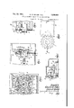
- Fig. 1 is 'a'sectionthrough the axes of thecutter and work spindles of a gear shaping machine
- Fig.2 is a cross section .on line 2-2 of Fig. 1;
- Fig, .3 is :an elevation of the parts at theright of line '133 in Fig. 1 asviewed from the direction of the arrows applied thereto;
- Fig. 5 is'a partial section taken on line 5- 5o f Fi 2;
- Fig. "6 is a .cletail view "o'fia gear shaper cutter in the courseof generating teeth in a gear blank, to illustrate the purpose and utility of the invention.
- C represents a gear shaper cutter and W represents a gear blank in which teeth are in course of being generatedand cut in accordance with the wellknown Fellows gear shaping process.
- Generation of correct tooth form in the work is assured by simultaneous rotation of the cutter about .its center 0 and the work about its center w at angular speeds 'inversely proportional to the number of. teeth of the "cutter and the number of teeth to be out in the Work.
- the teeth of the cutter first enter the work piece, they are more or less closely embraced by the uncutsubstance of the gear blank. As they traveltoward the point of separation, they deepen and widen .the slots or tooth spacesbeing cut.
- the cutter tooth .t is such an entering tooth, which has partially entered the gear blank and the tooth t is on thepoint of leaving the work.
- the material at the part m of the work piece makes extended and more or less overlapping contact with the side .of the tooth t, wherefore the relieving movement .of the cutter (assuming thatit is the cutter rather than the Work piece which is displaced for relief) is caused to take place'in a direction, indicated by the line c-a, which makes .an angle a: with the line of centers 0-10.
- the valueof the angle :0 is deter-- mined by the direction in which the tooth t must be displaced to clear fully the adjacent material m, but must not be so large as to cause interference of the relatively opposite side of any other tooth with the material of the work piece.
- Difierent conditions as of pitch and pressure angle of the cutter teeth; diameter of the gear blank, etc. generation of internal gears instead of external gears; reversal of the direction of rotation; etc.
- central feature of our present invention is provision for changing the value of the angle :12.
- a cutter spindle I0 which is both movable endwise and rotatable about its axis cc carries the cutter C
- a work spindle H rotatable about its axis w--w, carries the work piece W.
- Reciprocating motion is imparted to the cutter spindle from a main shaft I2 'by a crank l3 secured to the shaft, a connecting rod [4 coupled to the crank and having rack teeth 15 on one side, a gear IS in mesh with the rack teeth I5 and a sleeve I! surrounding the spindle and having rack teeth 18 with which the pinion l6 meshes.
- a single pinion or two pinions connected together coaxially may mesh with the teeth l5 and. I8 respectively.
- End thrust bearings l9 and 20 transmit endwise movement from the sleeve I!
- the internal diameter ofsleeve I1 is larger than the external diameterof that part of the spindle which passes through it, to permit lateral movement of the spindle for relieving purposes, as later described.
- Generative rotation is imparted to the spindle from a worm 24 meshing with a worm wheel 25, within which is secured a sleeve 26 having a guide 21 which engages a guide 28 secured to the spindle; said guides having abutting surfaces which transmit rotation to the spindle while permittingindependent endwise reciprocative movement of the latter.
- All of the parts described are mounted in a saddle or carriage 29 supported on a framework of any suitable character with provision for movement such as to alter the distance of the axis cc from the axis w-w and to place it at either side of the latter axis. 4
- the work spindle H is driven rotatably at a speed.
- All these driving means and the necessary provisions for mounting and shifting the carriage 29 as well, may be like or similar to those shown in the patent of Edward W. Miller 2,126,339, August 9, 1938, to which reference is directed for a full description.
- the ring 30 is so mounted that the axis NN may be located either perpendicular to the plane established by the spindle axes cc and w-w or at any angle within limits to said perpendicular position. It
- An external coaxial surface 39 on the ring 30 is visible through window 40 in the side of the housing 4
- is secured to the carriage 29 and supports bearings for the worm 24 while enclosing the worm wheel 25, ring 30, and associated parts.
- One side of the bushing is formed with shoulders 44 fitting between abutment blocks 45 which are secured to the interior frame structure of the cutter carriage by bolts 46 and nuts 41.
- the abutting faces of the shoulders 44 and blocks 45 are located at opposite sides of the plane of the axes cc and w-w, preferably equidistant from such plane, at the side of the spindle I0 toward which the spindle is moved for placement in the cutting path, after having been displaced for relief; and they are tapered convergently in the same direction.
- the blocks 45 are adjustable to vary the distance between their contact faces, whereby to arrest the shoulders 44 (and bushing 43) when the spindle has been placed in the exact location predetermined as its cutting path.
- the tapered or convergent disposition of said abutting surfaces not only centers the cutter spindle axis accurately in the prescribed plane with respect to the work spindle, but also permits withdrawal of the cutter spindle at different angles to said prescribed plane, within the limits of the angle of taper; and enables the location and inclination of the cutting path with respect to the work spindle axis to be varied by changing the distance between the abutments.
- a rigid tubular arm 48 is secured to the side of bushing 43 opposite to the shoulders 44 by means of bolts 49 passing through flanges at the base of the arm into the bushing.
- a transmission rod 50 is contained loosely in the interior bore of arm 48 and bears at its inner end against the head of a stud 5
- the outer end of rod 50 is engaged by an adjustable stud 52 threaded through one arm 53 of a bell crank lever which is mounted on a fixed pivot 54 in the carriage structure.
- the other arm 55 of said bell crank lever carries a roll 56 bearing on a cam 51, which we call the spindle relieving cam, mounted on the main shaft I 2.
- a helical spring 58 surrounds the tubular arm 48 and is held under compression between a collar 59 on the arm and an abutting surface 60 on a portion of the carriage structure.
- Arm 48 extends, and is movable endwise freely, through an opening dntthe structure .6.0.,: but. is iconstrained i fromlaiteral' movement zby :thehoundaries :ohsufihsopen-ing andzthereby preyentsthemushing A3;a'from ;being carried zendwise .by endwise iinouemen't ;of ;the
- the -;cam has nne .high xdwell one low dwell, each :extending through nearly half thecircumferenece ⁇ of the cam, joined by a .short rise and a short zdescent at ;opposite sidesof the center.
- the clamping bolts 36,2 pass zthrough arcuate slots in the block, ,concentric with'stud '63, :which have sufficient lengths to permit andjustment within the prescribeddimits.
- the end of the block next to the bushing :43 is provided with a plane surface :64- whichsma-y .be :set .;superallel-to the :plane established by the-spindle. axes .c--c and ww when the :cutter spindle is in working position, or at different angles, represented by the angles: in Fig. 6,:tousaidplane.
- ptheguiding face E l-of angle iblockifi'l is provided by a follower block 61 made as a segment of a cylinder having a plane chordal face to bear against the guide face 64 and a cylindrical face 58 which fits a complemental recess in the bushing.
- Said cylindrical-face BBand complemental recess are concentric with the pivot 63 whenthe bushing is in one of its positions, preferably the position of forcible engagement with the abutment blocks 4.5.
- the cutter spindle .10 and work spindle are consideredas holders for the t'ooland work piece respectively.
- One of such holders (in this case the cutter spindle 1B) is movable back andgforth'in-aggivenpath, '(i. -e., lengthwise of the spindle), to effect relative cutting traverse and return movements between the tool and workpiece.
- the ring .130 which 'carriesthe pivot trunnions for permitting relief movement of the cutter, .is considered as a pivot mounting between whichand oneof the above definedxholders .thereis a pivotal connection on an axistrans- .verse :to the path in which the movable holder is reciprocatedand perpendicular to the predetermined direction of relief separation.
- Adjustment of the pivot'mounting 30 to alter the direction of relief separation is generically defined as taking place about an axis extending in the same general direction as the path of cutting and return movements of the endwise movable holder. This generic definition applies to the'specific embodiment here illustrated since the axis of angular adjustment of the ring 30 coincides with the axis of :the work'spindle, which extends in the middle of the path of reciprocating movement of that spindle.
- is aguide for that holder which is pivotally connected to the pivot mounting.
- Such guide extends in'the predetermined direction of relief separation between the tool and work piece and is angularly adjustable to fix such direction as "predetermined.
- the axis of its angular adjustment (de- 'termined by the pivot pin 63) is parallel'to the axis around which the pivot mounting 30 is adjusted.
- a'means for caus- 1 ing separation between the tool and workpiece during the return movements and for varying the direction of such separation comprising a pivot mounting having a pivotal connection with one of said holders at a distance from the working locations of tool and work piece, the axis of such pivotal connection being transverse to the path of said cutting and return movements'and said mounting being'adjustable angularly about an axis extending in the same general direction as said path, andmechanism acting on said pivoted holder to swi'ngit about said axis in opposite directions in timed correlation with the said cutting and return movements.
- a means for producing separation between the cutter and a work piece to avoid rubbing contact during the return strokes of the cutter holder comprising a mounting with which one of said holders is in pivotal connection at a' distance from the working range of the cutter, with?
- said mounting being adjustable angularly in a manner to alter the direction of relief separation, and mechanism in timed relation to the cutter holder reciprocating means for swinging said pivoted holder in the direction to cause such separation at the end of the cutting strokes and in the opposite direction at the end of the return strokes.
- a shaping machine having a tool holder and a work holder, one of which is reciprocatory for effecting cutting traverse and return movement between a tool and a work piece, means supporting one of said holders with capacity for movement transversely of the path of said reciprocatory holder for effecting relief of the tool and work piece, one from the other, during the return movements of said reciprocatory holder, means for shifting said transversely movable holder alternately in the relieving'direction and in'the opposite direction, and guide means engaged with said shiftable holder and arranged with respect thereto for confining the relief and return movements of said shiftable holder to a predetermined path, said guide means being dis'placeable in a manner to alter the location of such path.
- a shaping machine having a tool holder and a work holder, one of which is reciprocatory for effecting cutting traverse and return movement'between a tool and work piece, means supporting one of saidholders with capacity for movement transversely of the path of said reciprocatory h'older foreffecting relief of thetool and work piece, one from" the other, during the return movements of said reciprocatory holder, means for shifting said transversely movable holder alternately in the relieving direction and in the opposite direction, and a guide extending in the direction of relief movement engaged with said shiftable holder, and with respect to which the holder is relatively movable in the relieving direction, for causing its movements of relief and return to take place in a predetermined path, said guide being angularly adjustable to shift the direction of said path.
- a cutter spindle a gear shaper cutter carried by said spindle, a work spindle, one of said spindles being reciprocatory endwise to eifect relative cutting traverse and return movements between said cutter and a work piece, one of said spindles being pivotally mounted at a distance from the zone of action of the cutter to swing about an axis transverse to the path of reciprocation of the reciprocatory spindle, means for adjusting the said axis in a plane transverse to said path whereby to vary the direction of said swinging movement, and means for shifting the swingable spindle through a distance suflicient to effect relief betweenthe cutter and work piece and to restore the cutter and work piece to their cutting relationship.
- a gear shaping machine having a cutter spindle, a gear shaper cutter secured to said spindle, a work spindle adapted to hold a gear blank, one of said spindles being reciprocatory endwise, means for reciprocating said spindle to effect relative cutting and return strokes between the cutter and work piece, a pivot mounting pivotally.
- said pivot mounting being angularly adjustable to cause the relief movement to occur in any predetermined direction within a given range
- a guide engaging said pivotally mounted spindle and having a guiding surface in a plane substantially perpendicular to said axis, said guide being angularly adjustableto set its guiding surface in different planesrespectively perpendicular to different positions of the axis.
- a shaping machine having a work holder and a cutter holder, one of which is reciprocatory to eifect relative cuttingand return strokes between a cutter mounted on the cutter holder and a work piece mounted on the work holder, one of said holders being movable transversely to the path of reciprocation of said reciprocatory holder to.
- transversely movable ease-see holder having shoulders with convergent external faces and the machine having fixed abutments for-engagement with said convergent faces to locate thetransversely movable holder" in an exact position during the cutting strokes; means for moving the lastnamed holder to withdraw said shoulders from said abutments and return the shoulders into contact with the abutments, an'daguide at one side of thetran'sversely-mow ableholder for causing its said transverse movements to take place-in a predetermined path;
- a gear shaping machine an endwise movable and rotatable spindle, a rotatable gear element surrounding said spindle, guide means between said gear element and spindle constructed to transmit rotation and permit endwise movement of the spindle relatively tothe gear element, a bearing for the gear element, a pivot mounting surrounding said bearing having pivot trunnions alined on a diameter of said bearing with which the bearing is engaged to permit swinging movement of the spindle transverse to its length, mechanism for reciprocating the spindle, and associated mechanism for swinging it about the axis of said trunnions in correlated timing with the reciprocating movements of the spindle, said pivot mounting being angularly adjustable about the axis of the spindle to vary and control the direction of said swinging movement.
- an endwise movable and rotatable cutter spindle adapted to carry a gear shaper cutter, means for transmitting rotation to said spindle while permitting its endwise movement, a pivot mounting pivotally connected to said spindle at a distance from the cutter location on an axis transverse to the axis of the spindle, a bushing surrounding the spindle near the cutter location having shoulders with convergent faces at one side of the diametral plane containing said pivot axis, fixed abutments arranged to engage said convergent shoulders for locating the bushing in a prescribed position, an arm projecting from the bushing at the opposite side thereof from the said shoulders and abutments, means acting on said arm for moving the bushing into and out of engagement with the abutments, and a guide engaging an intermediate side of the abutment for controlling the directions of the movements thus given to thef'bushing'.
- a guide for controlling the direction of such relief and return movements consisting of a stationary angularly adjustable block having a contact face, and a follower block having a complemental face in contact with the first named face,-
- a shaping machine having a supporting structure and a spindle mounted with provision for movement transversely of its length, a bushing surrounding said spindle, a guide block mounted on the supporting structure at one side of said bushing having a guiding face next to the bushing and being adjustable angularly about an axis substantially parallel to the length dimension of the spindle, and a follower block having a bounding surface concentric with the pivot axis of the guide block seated in a complemental recess in the side of the bushing and, having a contact face engaging the guide face of the guide block.
- a spindle movable back and forth endwise, guide means engaging said spindle adjacent to its opposite ends for controllingits path of movement, one of said guide means being shiftable transversely to said path and the other guide means being pivotally mounted to permit such shifting, the transversely shiftable guide means having separated contact faces inclined at relatively opposite inclinations to the direction of such shifting movements, and stationary abutments having contact faces separated from one another widely enough to permit entrance between and contact with them of the first named contact faces.
- a spindle movable back and forth endwise, guide means engaging said spindle adjacent to its opposite ends for controlling its path of movement, one of said guide means being shiftable transversely to: said path and the other guide means being pivotably mounted to permit such shifting, the transversely shiftable'gui'de means having separated contact faces" inclined at relatively opposite inclinations to the'direction of such shifting movements, and stationary abutments having contact faces sepa rated from one another widely enough to permit entrance between and contact with them of the first named contact faces,' said abutments being adjustable to vary the width of the space between their contact faces whereby to control anddetermine the location of said transversely shiftable guide means when in contact with the abutments.”
- a machine tool having a tool holder and a work holder, one of which holders is movable back and forth in a given path to efiect relative cutting traverse and return movements; means for causing separation between the tool and work piece during such return movements; comprising amounting having pivotal connection with one of said holders at a distance from the working locations of tool and work piece on an axis transverse to the path oi said cutting and return movements and perpendicular to the predetermined direction of separation, a-guide in cooperating relation with said holder at a distance from said pivot axis extending insaid predetermined direction for controlling the path of the pivoted holder in the course of such separations, both said pivot mounting and guide being adjustable angularly in a manner to alter the direction in which the separation between the, tool and work piece is constrained to take place, and means for swinging the pivoted holder back and forth in the directions'constrained by said guide and in timed correlationwith said cutting EDWARD W. Mn E f EVERARD STUBBS.
Landscapes
- Engineering & Computer Science (AREA)
- Mechanical Engineering (AREA)
- Milling Processes (AREA)
Description
Dec. 23, 1941.
E. w. MILLER ETAL CUTTER RELIEVING MEANS FOR SI'LA'PHIG MACHINES 1 Filed Oct. 16, 1939 -2 Sheets-Sheet l imam %/M%f {w g/d (1922M Dec. 2 3, 1941.
E. W. MILLER ET AL CUTTER RELIEVING MEANS FOR SHAPING MACHINES Filed oct. 16, 1959 2 Sheets-Sheet 2 mm; y/m'm Patented Dec. 23, 1941 CUTTER RELIEVING MEANS non SHARING LMAOHINE'S.
Edward W. Miller and Everard Stubbs, Springfield, Vt.,:assignors to The Fellows .GearShaper Company, Springfield, Vt.,
Vermont .a corporation of Application October 16, 1939, SerialNo. 299,620
"LG-Claims.
-This invention relates to machines of the type in which cutting is performed by a relative reciprocating movement between a cutting tool and a .workpiece, where the cutting action is effected during movement in one direction and a separation is produced between the tooland work during movement in the opposite direction .to prevent rubbing of the tool on the workat such times. .It is more particularly concerned with shaping machines, suchas those Iorcutting. gears and similar articles. by means of a-gear-likeplaning cutter, where the tool cuts grooves in the work piece and also generates .curvesof a prescribedl'iormon thesides .of the groovesin consequence of a generative rotation .of .the cutter and I relief movements are given .to a spindle which carries the cutter, and the cutter spindle and work spindle .are .rotated about different axes, oneof which coincides with the pathofrreciprocation of thecutterspindle. This showing, however, is not to be construed as a limitationof the invention to that specific embodiment. In its broader aspects the-invention consists ina means for adjusting the angle of relieving motion or back-off between cutter and work in a shaping machine. More specifically it consists in the principles .of the means for efiecting such relief movementdiscloseddn the following specification, and thedetails thereof, together with'combina- .tions'of {such principles and means with 'cooperating parts of the machine, and all equivalentsof the {particulars herein disclosed.
In the drawings,
Fig. 1 is 'a'sectionthrough the axes of thecutter and work spindles of a gear shaping machine,
showing so much of the associated parts of the machine as necessary for explanation of'the present invention. The plane of this section :is indicated bytheline i-| inFigsrZ and 3;
Fig.2 is a cross section .on line 2-2 of Fig. 1;
:Fig, .3 is :an elevation of the parts at theright of line '133 in Fig. 1 asviewed from the direction of the arrows applied thereto;
"Fig. "4'is'a detail section on line :4-4 of Fig. 3;
Fig. 5 is'a partial section taken on line 5- 5o f Fi 2;
Fig. "6 is a .cletail view "o'fia gear shaper cutter in the courseof generating teeth in a gear blank, to illustrate the purpose and utility of the invention.
Like reference characters designate the same parts whereverthey occur'in allthe figures.
Referring first to Fig. 6, C represents a gear shaper cutter and W represents a gear blank in which teeth are in course of being generatedand cut in accordance with the wellknown Fellows gear shaping process. Generation of correct tooth form in the work is assured by simultaneous rotation of the cutter about .its center 0 and the work about its center w at angular speeds 'inversely proportional to the number of. teeth of the "cutter and the number of teeth to be out in the Work. When the teeth of the cutter first enter the work piece, they are more or less closely embraced by the uncutsubstance of the gear blank. As they traveltoward the point of separation, they deepen and widen .the slots or tooth spacesbeing cut. Assuming that the cutter and gear blank here shown are rotated in the direction of the arrows, the cutter tooth .t is such an entering tooth, which has partially entered the gear blank and the tooth t is on thepoint of leaving the work. The material at the part m of the work piece makes extended and more or less overlapping contact with the side .of the tooth t, wherefore the relieving movement .of the cutter (assuming thatit is the cutter rather than the Work piece which is displaced for relief) is caused to take place'in a direction, indicated by the line c-a, which makes .an angle a: with the line of centers 0-10. The valueof the angle :0 is deter-- mined by the direction in which the tooth t must be displaced to clear fully the adjacent material m, but must not be so large as to cause interference of the relatively opposite side of any other tooth with the material of the work piece. Difierent conditions (as of pitch and pressure angle of the cutter teeth; diameter of the gear blank, etc. generation of internal gears instead of external gears; reversal of the direction of rotation; etc.) in a machine designed for doing a wide variety of work, require the angle as to be varied in degree, and may require it to be shifted from one side to theother of the line of centers. in some cases the angle may be zero, while in Others it may have appreciable magnitude. The
central feature of our present invention is provision for changing the value of the angle :12.
We have here illustrated an embodiment of such means in connection with a gear shaping machine in which the cutter spindle and work spindle are horizontal with their axes parallel. A cutter spindle I0, which is both movable endwise and rotatable about its axis cc carries the cutter C, and a work spindle H, rotatable about its axis w--w, carries the work piece W. The
latter may be a gear blank or any character secured to the work spindle by any suitable clamp-' ing or other holding means.
Reciprocating motion is imparted to the cutter spindle from a main shaft I2 'by a crank l3 secured to the shaft, a connecting rod [4 coupled to the crank and having rack teeth 15 on one side, a gear IS in mesh with the rack teeth I5 and a sleeve I! surrounding the spindle and having rack teeth 18 with which the pinion l6 meshes. Either a single pinion or two pinions connected together coaxially may mesh with the teeth l5 and. I8 respectively. End thrust bearings l9 and 20 transmit endwise movement from the sleeve I! to the spindle; in one direction by means of a shoulder 2| on the spindle and in the opposite direction through a washer 22 and nut 23 secured to the spindle. The internal diameter ofsleeve I1 is larger than the external diameterof that part of the spindle which passes through it, to permit lateral movement of the spindle for relieving purposes, as later described.
Generative rotation is imparted to the spindle from a worm 24 meshing with a worm wheel 25, within which is secured a sleeve 26 having a guide 21 which engages a guide 28 secured to the spindle; said guides having abutting surfaces which transmit rotation to the spindle while permittingindependent endwise reciprocative movement of the latter.. All of the parts described are mounted in a saddle or carriage 29 supported on a framework of any suitable character with provision for movement such as to alter the distance of the axis cc from the axis w-w and to place it at either side of the latter axis. 4 The work spindle H is driven rotatably at a speed. and in a direction harmonious with the rotation of the cutter, by means of a Worm 399 meshing with a Worm wheel39l which forms an operative part of the work spindle; the relative rotational speeds of worms 399 and 24 being correlated by suitable change gears.
All these driving means and the necessary provisions for mounting and shifting the carriage 29 as well, may be like or similar to those shown in the patent of Edward W. Miller 2,126,339, August 9, 1938, to which reference is directed for a full description.
of the worm wheel 25 is mounted adjacent to the outerend of the cutter spindle. This ring supports trunnions 32 and 33 alined on an axis NN perpendicular to the spindle axis cc, and the bearing sleeve 31 is mounted on these trunnions so as to swing about the axis NN. The ring 30 is so mounted that the axis NN may be located either perpendicular to the plane established by the spindle axes cc and w-w or at any angle within limits to said perpendicular position. It
is clamped to the carriage structure by bolts 34 passing through slots 35 in a flange 36, which forms part of the structure of the ring, and received in tapped holes in the carriage structure. Studs 31 mounted in the adjacent structure of the carriage are engaged by the inner surface 38 of the ring and serve to center the latter. They are accurately located at proper distances from the spindle axis and the surface 38 is accurately made with cylindrical arcs coaxial with the same axis whereby to maintain the intersection of the axes cc and NN at the same point ,during and after adjustment of the ring, without depending on the clamping bolts 34 and slots 35 for the centering function.
An external coaxial surface 39 on the ring 30 is visible through window 40 in the side of the housing 4| and carries a scale of angular degrees (or equivalent graduations) cooperating with a pointer 42 to show the position of the ring. With the aid of such pointer and graduations the operator is enabled to set the trunnions so as to permit relief movement of the cutter at any desired angle to the plane of the cutter and work spindle axes. Housing 4| is secured to the carriage 29 and supports bearings for the worm 24 while enclosing the worm wheel 25, ring 30, and associated parts.
The inner end of the spindle Ill, thaton the extremity of which the cutter C is mounted, is fitted, with a close sliding fit, in a guide'bushing 43. One side of the bushing is formed with shoulders 44 fitting between abutment blocks 45 which are secured to the interior frame structure of the cutter carriage by bolts 46 and nuts 41. The abutting faces of the shoulders 44 and blocks 45 are located at opposite sides of the plane of the axes cc and w-w, preferably equidistant from such plane, at the side of the spindle I0 toward which the spindle is moved for placement in the cutting path, after having been displaced for relief; and they are tapered convergently in the same direction. The blocks 45 are adjustable to vary the distance between their contact faces, whereby to arrest the shoulders 44 (and bushing 43) when the spindle has been placed in the exact location predetermined as its cutting path. The tapered or convergent disposition of said abutting surfaces not only centers the cutter spindle axis accurately in the prescribed plane with respect to the work spindle, but also permits withdrawal of the cutter spindle at different angles to said prescribed plane, within the limits of the angle of taper; and enables the location and inclination of the cutting path with respect to the work spindle axis to be varied by changing the distance between the abutments.
A rigid tubular arm 48 is secured to the side of bushing 43 opposite to the shoulders 44 by means of bolts 49 passing through flanges at the base of the arm into the bushing. A transmission rod 50 is contained loosely in the interior bore of arm 48 and bears at its inner end against the head of a stud 5| which is set into the structure of the arm at the base of the bore. The outer end of rod 50 is engaged by an adjustable stud 52 threaded through one arm 53 of a bell crank lever which is mounted on a fixed pivot 54 in the carriage structure. The other arm 55 of said bell crank lever carries a roll 56 bearing on a cam 51, which we call the spindle relieving cam, mounted on the main shaft I 2. A helical spring 58 surrounds the tubular arm 48 and is held under compression between a collar 59 on the arm and an abutting surface 60 on a portion of the carriage structure. Arm 48 extends, and is movable endwise freely, through an opening dntthe structure .6.0.,: but. is iconstrained i fromlaiteral' movement zby :thehoundaries :ohsufihsopen-ing andzthereby preyentsthemushing A3;a'from ;being carried zendwise .by endwise iinouemen't ;of ;the
spindle when the bushing lis .lllearidf'ithe :abut- I menthlocks .45.
It will be ,plain that the high :portion :of the relieTln .cam :51, acting vj-through ;.le,ver 153-55 and transmission rod 50, serves to blotting the shoulders 44 into contact with :the abutment blocks 45 and to !exert a pressure tadalustable by screwsrstud 52) sufficientxtoaholddihe bushing rigidly in position. Spring 158 ntends constantly :to withdraw the bushing :from "the vzahut-ment -blocks and .doesaso withdraw it when permitted by the cam, holding the :followerroll d'zB against the relieving cam. In tthe :iorganization .here represented, the -;cam has nne .high xdwell one low dwell, each :extending through nearly half thecircumferenece {of the cam, joined by a .short rise and a short zdescent at ;opposite sidesof the center. Thezceanrotatesjn uxnison with the crankshaft ;-l.-2;and1is=:so located asritc shift the i-spindleinto its cutting :pathz-pricrstp the-commencement of each acut-ting stroke :and permit relieving withdrawal ,of the cutter :spindle "at the end of each cutting stroke. .The movement thus .given to {the spindle sufficient .to shift the cutter clear of the work, :but in actual .dimensions .is too small to :be shown accurately on a drawing .of such small jzscale :as .that accompanying this specification. Hence the difference between :thehigh .and iowparts of .-the cam has beengshown with aekaggeration'jn this drawing.
In its withdrawal for relief iandwreturn prior :to cutting strokes of the spindle, bushing 43 ;is
guided by an angle block Bl at :oneof theasides of the bushing intermediate the shoulders :46 and arm 48. .Angle block-5| fiistsetiinto :a "recess in the face of the cuttermarriagetZBuatdiaoentaxto the bushing and is clamped against theibottom of the recess by bolts (preferably threeaorimore innumber) ,62. It is angularl-y adjustable about :aIi-xed stud 6.3 which is set .in'the carriage structure and enters a recess in the rearrfacegofzthe block. The clamping bolts 36,2 pass zthrough arcuate slots in the block, ,concentric with'stud '63, :which have sufficient lengths to permit andjustment within the prescribeddimits. The end of the block next to the bushing :43 is provided with a plane surface :64- whichsma-y .be :set .;paarallel-to the :plane established by the-spindle. axes .c--c and ww when the :cutter spindle is in working position, or at different angles, represented by the angles: in Fig. 6,:tousaidplane. A
:scale of angular degrees 65 on the ;exposedi'face of the :block 6! adjacent to its outer .end, and a fixed pointer 66 show the setting of the face 64 and guide the machine operator 'insetting said face to any desired value of the angle 1.1;.
.A .complemental surface to cooperate :with
ptheguiding face E l-of angle iblockifi'l ;is provided by a follower block 61 made as a segment of a cylinder having a plane chordal face to bear against the guide face 64 and a cylindrical face 58 which fits a complemental recess in the bushing. Said cylindrical-face BBand complemental recess are concentric with the pivot 63 whenthe bushing is in one of its positions, preferably the position of forcible engagement with the abutment blocks 4.5. Hence .whenguide orangle .hlock 6| is adjusted around the pivot .6.3,.the fol- .lower bloc-k 6! is correspondingly shifted and its :contactasurfacetbrought to-the :sameinclination as :zthegguiding surface 64. .As :a :oonveniientcdetail-rof construction, the outer wall :of :the recess an "the bushing which contains -:the :followerzzblock :6 is formed e-by'a removable plat -69 bolted .to the ienjd'of-ithe .loushing. .A ihelical :spring 111] ,is contained .;in -.a passage- -waythrougharpart of the carriage structureaat :the aopposite :side .;of 317118 :bushing 43 from %the angle :guide blocksfizl. Thisspringbears at one end against "the bushing and :reacts :against an abutment-screw 1| esetlinto the carriage structure and Eloy-which the :spring :is compressed. -Ifhe :spring.1-theltefoue,;holds :the follower ablock in contactwiththeeguiding,surfaceilizd when the hushingjris clear :of ;the-;abutment :blocks :45 andcausesathe rbushing to move in the-path mnescribed .:by 'the ;said .guiding surface in relieving the mutter andrinzreturni-ng to the worh'ingzrpath It isn'nherent in the:descriptiomand:drawings fthatthe ..-gniding face lies an ;a plane perpenzdicularztotherpiyotaxis NN-.when adjusted parallel to the common plane of the cuttersand work spindle LLEXESTdI'Id when the :pivot axis :N-N is perpendicular to that plane. Whenaheaaxis iNwNi'is shifted to any given :ang-leirom said perpendicular position and ithe -face'-.li l ;isshi-ft- :ed ito an equakangleof -the:same hand f-romesaid parallel position, the spindle ispermitt-edacand constrained to move at the .same angle to the :line :of centers :in .beingarelieved from ithework and returned to {the :cuttingma-th. :Hence the igraduationsyrfifi on the :blOGk'B'l and those Ton the.:face':39aof;ring 3,9 enable the operator to :adiiust the relieving :means quickly and accurately :to relieve the .cutter any direction l rescribed .hy tits -.icharact.eristics=1and 1 the "character :of the \gear :to Ebe rout. A more :exact determination ga-nd maintenance of the ,path 10f irelief made possiblerwith :the aid of fthe guiding face :64 than by the'rtrunnions 132 and :33 alone or any. means heretofore :used.
Although vie-have described :ithe application of our relieving nneans to .the cutter spindle of a :gear shaping -rmach-ine, we 'sWiSh to .make "it 'understuodgthat fitisnotzrestricted to useswith thistypeofrmachineoflly or to-thecutter spin-- .dle :as distinguished from the work: spindle *of '12, machine, ;or :to zareciprocating spindle (whether rotatory .ormot) rather than a spindle "which is stationary except for such relief movement. The principles ;of our-adjustable relieving. means may be (combined-with .the :tool holding or work holding means -of various machines in a :wide yariety of embodiments and combinations. Wherever aprovision exists for --swinging lateral movement --of a tool or work holder and for adjustment and guiding of the direction of .such swinging movement, there our invention may she applied.
.For the purpose -,of generic definition .in the claims, the cutter spindle .10 and work spindle are consideredas holders for the t'ooland work piece respectively. One of such holders (in this case the cutter spindle 1B) is movable back andgforth'in-aggivenpath, '(i. -e., lengthwise of the spindle), to effect relative cutting traverse and return movements between the tool and workpiece. The ring .130, which 'carriesthe pivot trunnions for permitting relief movement of the cutter, .is considered as a pivot mounting between whichand oneof the above definedxholders .thereis a pivotal connection on an axistrans- .verse :to the path in which the movable holder is reciprocatedand perpendicular to the predetermined direction of relief separation. Adjustment of the pivot'mounting 30 to alter the direction of relief separation is generically defined as taking place about an axis extending in the same general direction as the path of cutting and return movements of the endwise movable holder. This generic definition applies to the'specific embodiment here illustrated since the axis of angular adjustment of the ring 30 coincides with the axis of :the work'spindle, which extends in the middle of the path of reciprocating movement of that spindle.
r The face 64 of the angle block 6| is aguide for that holder which is pivotally connected to the pivot mounting. Such guide extends in'the predetermined direction of relief separation between the tool and work piece and is angularly adjustable to fix such direction as "predetermined. The axis of its angular adjustment (de- 'termined by the pivot pin 63) is parallel'to the axis around which the pivot mounting 30 is adjusted.
What We claim and desire to secure by Letters Patent is: I
1. In a machine tool having a tool holder and a work holder, one of which holders is movable back and forth in a given path to efi'ect relative cutting and return movements, a'means for caus- 1 ing separation between the tool and workpiece during the return movements and for varying the direction of such separation, comprising a pivot mounting having a pivotal connection with one of said holders at a distance from the working locations of tool and work piece, the axis of such pivotal connection being transverse to the path of said cutting and return movements'and said mounting being'adjustable angularly about an axis extending in the same general direction as said path, andmechanism acting on said pivoted holder to swi'ngit about said axis in opposite directions in timed correlation with the said cutting and return movements.
2. In a machine tool having a reciprocatory cutter holder, a work holder, and means for reciprocating the cutter holder to perform alternate cutting and return strokes, a means for producing separation between the cutter and a work piece to avoid rubbing contact during the return strokes of the cutter holder comprising a mounting with which one of said holders is in pivotal connection at a' distance from the working range of the cutter, with? the axis of said pivotal connection transverse to the path of movement of said reciprocatory holder and also to the predetermined direction of such relief separation, said mounting being adjustable angularly in a manner to alter the direction of relief separation, and mechanism in timed relation to the cutter holder reciprocating means for swinging said pivoted holder in the direction to cause such separation at the end of the cutting strokes and in the opposite direction at the end of the return strokes.
3. In a shaping machine having a tool holder and a work holder, one of which is reciprocatory for effecting cutting traverse and return movement between a tool and a work piece, means supporting one of said holders with capacity for movement transversely of the path of said reciprocatory holder for effecting relief of the tool and work piece, one from the other, during the return movements of said reciprocatory holder, means for shifting said transversely movable holder alternately in the relieving'direction and in'the opposite direction, and guide means engaged with said shiftable holder and arranged with respect thereto for confining the relief and return movements of said shiftable holder to a predetermined path, said guide means being dis'placeable in a manner to alter the location of such path.
4. In a shaping machine having a tool holder and a work holder, one of which is reciprocatory for effecting cutting traverse and return movement'between a tool and work piece, means supporting one of saidholders with capacity for movement transversely of the path of said reciprocatory h'older foreffecting relief of thetool and work piece, one from" the other, during the return movements of said reciprocatory holder, means for shifting said transversely movable holder alternately in the relieving direction and in the opposite direction, and a guide extending in the direction of relief movement engaged with said shiftable holder, and with respect to which the holder is relatively movable in the relieving direction, for causing its movements of relief and return to take place in a predetermined path, said guide being angularly adjustable to shift the direction of said path.
6. In a gear shaping machine having a cutter spindle, a gear shaper cutter secured to said spindle, a work spindle adapted to hold a gear blank, one of said spindles being reciprocatory endwise, means for reciprocating said spindle to effect relative cutting and return strokes between the cutter and work piece, a pivot mounting pivotally. connected with one of said spindles at a distance from the cutter and on an axis transverse to the path of the reciprocatory spindle, to permit relief separation between the cutter and work piece, said pivot mounting being angularly adjustable to cause the relief movement to occur in any predetermined direction within a given range, and a guide engaging said pivotally mounted spindle and having a guiding surface in a plane substantially perpendicular to said axis, said guide being angularly adjustableto set its guiding surface in different planesrespectively perpendicular to different positions of the axis.
7. In a shaping machine having a work holder and a cutter holder, one of which is reciprocatory to eifect relative cuttingand return strokes between a cutter mounted on the cutter holder and a work piece mounted on the work holder, one of said holders being movable transversely to the path of reciprocation of said reciprocatory holder to. permit relieving separation between the cutter and work piece during return strokes and to place them in cutting relationship during the cutting strokes, said transversely movable ease-see holder having shoulders with convergent external faces and the machine having fixed abutments for-engagement with said convergent faces to locate thetransversely movable holder" in an exact position during the cutting strokes; means for moving the lastnamed holder to withdraw said shoulders from said abutments and return the shoulders into contact with the abutments, an'daguide at one side of thetran'sversely-mow ableholder for causing its said transverse movements to take place-in a predetermined path;
' 8 In a'shaping machine'havingawork'holder and a cutter holder, one of which is recipro= catory to effect relative cutting and return strokes between acutter'mounted on the cutter holder and a" work piecemount'edori the work holder, one of said holders being movable trans versely to the path of reciprocationofsaidreciprocatory holder to permit relieving separation between the cutter and work piece during return strokes and to place them in cutting relationship during-the cutting" strokes, said transversely movable holder having shoulders with convergent external faces and the machine having fixed abutments for engagement with said convergent faces to locate the transversely movable holder in an exact position during the cutting strokes, means for moving the last named holder to withdraw said shoulders from said abutments and return the shoulders into contact with the abutments, and a guide at one side of the transversely movable holder for causing its said transverse movements to take place in a predetermined path, said guide being angularly adjustable to vary and determine the direction of such transverse movement.
9. In a gear shaping machine, an endwise movable and rotatable spindle, a rotatable gear element surrounding said spindle, guide means between said gear element and spindle constructed to transmit rotation and permit endwise movement of the spindle relatively tothe gear element, a bearing for the gear element, a pivot mounting surrounding said bearing having pivot trunnions alined on a diameter of said bearing with which the bearing is engaged to permit swinging movement of the spindle transverse to its length, mechanism for reciprocating the spindle, and associated mechanism for swinging it about the axis of said trunnions in correlated timing with the reciprocating movements of the spindle, said pivot mounting being angularly adjustable about the axis of the spindle to vary and control the direction of said swinging movement.
10. In a gear shaping machine, an endwise movable and rotatable cutter spindle adapted to carry a gear shaper cutter, means for transmitting rotation to said spindle while permitting its endwise movement, a pivot mounting pivotally connected to said spindle at a distance from the cutter location on an axis transverse to the axis of the spindle, a bushing surrounding the spindle near the cutter location having shoulders with convergent faces at one side of the diametral plane containing said pivot axis, fixed abutments arranged to engage said convergent shoulders for locating the bushing in a prescribed position, an arm projecting from the bushing at the opposite side thereof from the said shoulders and abutments, means acting on said arm for moving the bushing into and out of engagement with the abutments, and a guide engaging an intermediate side of the abutment for controlling the directions of the movements thus given to thef'bushing'. h A,
ll. In a gear shapingmachine, a an' endwise movable'an'd rotatable cutter spindle-"adapted? to carry a gear shaperfcutter, means for transmit' ting rotation to said spindle "while permittin'gf its endwise movement, a; pivot m untin pivotally connected to said= spindleata distance from the cutter-location on-anaxistransverseto the axis of the spindle; abushingsurroundingcthe spindle near thecutter location having shoulders with convergent faces -at one-side of the diam} et-ral plane containing said' pivot" axis fixed abut= ments arranged-to engage 'said convergent sl'ioulders for locat-ing the bushing in 'a prescribed to; sition, an arm projecting from the bushingattlfe" opposite side thereof from the said shoulders and-abutments; means acting on" said aIIllIfOI" movingthebushin'g into and out of engagem'ent with the abutments; and a guide? engagingen intermediate side" of the abutment" for e-antral: ling the directions"ofthemovements thus given to the bushing, said pivot mounting and guide being angularly adjustable in correlation with one another to vary the direction of said movements of the bushing.
12. In a machine tool having cutter and work holders, one of which is movable in a given path to efiect cutting and return strokes, and one of which is movable transversely of such path to effect relief between the cutter and work piece, and return thereof to cutting relationship, a guide for controlling the direction of such relief and return movements consisting of a stationary angularly adjustable block having a contact face, and a follower block having a complemental face in contact with the first named face,-
and a bounding surface which is coaxial with the axis of angular adjustment of the first named 7 block, one of said blocks being mounted on the supporting structure of the machine and the other being mounted on said transversely movable holder, the coaxial bounding surface of the follower block enabling it to be self adjusting to angular adjustments of the guide block.
13. In a shaping machine having a supporting structure and a spindle mounted with provision for movement transversely of its length, a bushing surrounding said spindle, a guide block mounted on the supporting structure at one side of said bushing having a guiding face next to the bushing and being adjustable angularly about an axis substantially parallel to the length dimension of the spindle, and a follower block having a bounding surface concentric with the pivot axis of the guide block seated in a complemental recess in the side of the bushing and, having a contact face engaging the guide face of the guide block.
14. In a shaping machine, a spindle movable back and forth endwise, guide means engaging said spindle adjacent to its opposite ends for controllingits path of movement, one of said guide means being shiftable transversely to said path and the other guide means being pivotally mounted to permit such shifting, the transversely shiftable guide means having separated contact faces inclined at relatively opposite inclinations to the direction of such shifting movements, and stationary abutments having contact faces separated from one another widely enough to permit entrance between and contact with them of the first named contact faces.
15. In a shaping machine a spindle movable back and forth endwise, guide means engaging said spindle adjacent to its opposite ends for controlling its path of movement, one of said guide means being shiftable transversely to: said path and the other guide means being pivotably mounted to permit such shifting, the transversely shiftable'gui'de means having separated contact faces" inclined at relatively opposite inclinations to the'direction of such shifting movements, and stationary abutments having contact faces sepa rated from one another widely enough to permit entrance between and contact with them of the first named contact faces,' said abutments being adjustable to vary the width of the space between their contact faces whereby to control anddetermine the location of said transversely shiftable guide means when in contact with the abutments." g
16. In a machine tool having a tool holder and a work holder, one of which holders is movable back and forth in a given path to efiect relative cutting traverse and return movements; means for causing separation between the tool and work piece during such return movements; comprising amounting having pivotal connection with one of said holders at a distance from the working locations of tool and work piece on an axis transverse to the path oi said cutting and return movements and perpendicular to the predetermined direction of separation, a-guide in cooperating relation with said holder at a distance from said pivot axis extending insaid predetermined direction for controlling the path of the pivoted holder in the course of such separations, both said pivot mounting and guide being adjustable angularly in a manner to alter the direction in which the separation between the, tool and work piece is constrained to take place, and means for swinging the pivoted holder back and forth in the directions'constrained by said guide and in timed correlationwith said cutting EDWARD W. Mn E f EVERARD STUBBS.-
Priority Applications (1)
| Application Number | Priority Date | Filing Date | Title |
|---|---|---|---|
| US299620A US2266889A (en) | 1939-10-16 | 1939-10-16 | Cutter relieving means for shaping machines |
Applications Claiming Priority (1)
| Application Number | Priority Date | Filing Date | Title |
|---|---|---|---|
| US299620A US2266889A (en) | 1939-10-16 | 1939-10-16 | Cutter relieving means for shaping machines |
Publications (1)
| Publication Number | Publication Date |
|---|---|
| US2266889A true US2266889A (en) | 1941-12-23 |
Family
ID=23155567
Family Applications (1)
| Application Number | Title | Priority Date | Filing Date |
|---|---|---|---|
| US299620A Expired - Lifetime US2266889A (en) | 1939-10-16 | 1939-10-16 | Cutter relieving means for shaping machines |
Country Status (1)
| Country | Link |
|---|---|
| US (1) | US2266889A (en) |
Cited By (6)
| Publication number | Priority date | Publication date | Assignee | Title |
|---|---|---|---|---|
| US2640397A (en) * | 1945-08-02 | 1953-06-02 | Fellows Gear Shaper Co | Reversing feed gear shaping machine |
| US2643583A (en) * | 1947-02-01 | 1953-06-30 | Fellows Gear Shaper Co | Machine for cutting and finishing gears, etc., by form cutters |
| US2669906A (en) * | 1948-03-24 | 1954-02-23 | Fellows Gear Shaper Co | Gear shaper |
| US2756642A (en) * | 1945-08-02 | 1956-07-31 | Fellows Gear Shaper Co | Reversing feed gear shaping method |
| US3107580A (en) * | 1960-08-23 | 1963-10-22 | Eda Masumi | Gear shaper |
| US3318194A (en) * | 1965-07-22 | 1967-05-09 | Fellows Gear Shaper Co | Gear shaper back-off mechanism |
-
1939
- 1939-10-16 US US299620A patent/US2266889A/en not_active Expired - Lifetime
Cited By (6)
| Publication number | Priority date | Publication date | Assignee | Title |
|---|---|---|---|---|
| US2640397A (en) * | 1945-08-02 | 1953-06-02 | Fellows Gear Shaper Co | Reversing feed gear shaping machine |
| US2756642A (en) * | 1945-08-02 | 1956-07-31 | Fellows Gear Shaper Co | Reversing feed gear shaping method |
| US2643583A (en) * | 1947-02-01 | 1953-06-30 | Fellows Gear Shaper Co | Machine for cutting and finishing gears, etc., by form cutters |
| US2669906A (en) * | 1948-03-24 | 1954-02-23 | Fellows Gear Shaper Co | Gear shaper |
| US3107580A (en) * | 1960-08-23 | 1963-10-22 | Eda Masumi | Gear shaper |
| US3318194A (en) * | 1965-07-22 | 1967-05-09 | Fellows Gear Shaper Co | Gear shaper back-off mechanism |
Similar Documents
| Publication | Publication Date | Title |
|---|---|---|
| US2266889A (en) | Cutter relieving means for shaping machines | |
| GB834016A (en) | Improvements in or relating to a machine tool | |
| US2282193A (en) | Method and apparatus for cutting gears | |
| US2280045A (en) | Gear finishing machine | |
| US2771799A (en) | Thread rolling tool | |
| US2089078A (en) | Taper attachment for lathes | |
| US3835528A (en) | Sphere and angle turning attachment for milling machines | |
| US2125304A (en) | Cutter relieving means for shaping machines | |
| US2433048A (en) | Lathe | |
| US2125873A (en) | Shaping machine | |
| US2184684A (en) | Form producing machine | |
| US2379405A (en) | Milling machine | |
| US2257850A (en) | Generative gear grinding machine | |
| US2008474A (en) | Apparatus for turning noncircular work | |
| US3114294A (en) | Machine tool attachment | |
| US3301104A (en) | Apparatus for turning curved surfaces | |
| US4302992A (en) | Piston turning machine | |
| US2859667A (en) | Machine tool table mechanism | |
| US3213755A (en) | Method and machine for producing spiral bevel and hypoid gears | |
| US2799075A (en) | Machine tool | |
| US3054332A (en) | Spiral bevel and hypoid gear cutting machine | |
| US1662109A (en) | High-speed-gear-generating machine | |
| US2143258A (en) | Cam making machine | |
| US3533328A (en) | Copying machine tool | |
| US2376110A (en) | Machine for machining screw gears |