US2259029A - Sludge separator - Google Patents
Sludge separator Download PDFInfo
- Publication number
- US2259029A US2259029A US155316A US15531637A US2259029A US 2259029 A US2259029 A US 2259029A US 155316 A US155316 A US 155316A US 15531637 A US15531637 A US 15531637A US 2259029 A US2259029 A US 2259029A
- Authority
- US
- United States
- Prior art keywords
- tank
- sludge
- wall
- inlet
- separator
- Prior art date
- Legal status (The legal status is an assumption and is not a legal conclusion. Google has not performed a legal analysis and makes no representation as to the accuracy of the status listed.)
- Expired - Lifetime
Links
- 239000010802 sludge Substances 0.000 title description 47
- 239000007788 liquid Substances 0.000 description 20
- 239000000428 dust Substances 0.000 description 10
- 239000002002 slurry Substances 0.000 description 10
- XLYOFNOQVPJJNP-UHFFFAOYSA-N water Substances O XLYOFNOQVPJJNP-UHFFFAOYSA-N 0.000 description 4
- 239000012530 fluid Substances 0.000 description 2
- 229940000425 combination drug Drugs 0.000 description 1
- 238000010276 construction Methods 0.000 description 1
- 238000004519 manufacturing process Methods 0.000 description 1
- 230000000737 periodic effect Effects 0.000 description 1
- 239000013049 sediment Substances 0.000 description 1
Images
Classifications
-
- B—PERFORMING OPERATIONS; TRANSPORTING
- B01—PHYSICAL OR CHEMICAL PROCESSES OR APPARATUS IN GENERAL
- B01D—SEPARATION
- B01D21/00—Separation of suspended solid particles from liquids by sedimentation
- B01D21/24—Feed or discharge mechanisms for settling tanks
- B01D21/245—Discharge mechanisms for the sediments
- B01D21/2461—Positive-displacement pumps; Screw feeders; Trough conveyors
-
- B—PERFORMING OPERATIONS; TRANSPORTING
- B01—PHYSICAL OR CHEMICAL PROCESSES OR APPARATUS IN GENERAL
- B01D—SEPARATION
- B01D21/00—Separation of suspended solid particles from liquids by sedimentation
- B01D21/003—Sedimentation tanks provided with a plurality of compartments separated by a partition wall
-
- B—PERFORMING OPERATIONS; TRANSPORTING
- B01—PHYSICAL OR CHEMICAL PROCESSES OR APPARATUS IN GENERAL
- B01D—SEPARATION
- B01D21/00—Separation of suspended solid particles from liquids by sedimentation
- B01D21/0039—Settling tanks provided with contact surfaces, e.g. baffles, particles
- B01D21/0042—Baffles or guide plates
-
- B—PERFORMING OPERATIONS; TRANSPORTING
- B01—PHYSICAL OR CHEMICAL PROCESSES OR APPARATUS IN GENERAL
- B01D—SEPARATION
- B01D21/00—Separation of suspended solid particles from liquids by sedimentation
- B01D21/02—Settling tanks with single outlets for the separated liquid
-
- B—PERFORMING OPERATIONS; TRANSPORTING
- B01—PHYSICAL OR CHEMICAL PROCESSES OR APPARATUS IN GENERAL
- B01D—SEPARATION
- B01D21/00—Separation of suspended solid particles from liquids by sedimentation
- B01D21/24—Feed or discharge mechanisms for settling tanks
- B01D21/2405—Feed mechanisms for settling tanks
- B01D21/2411—Feed mechanisms for settling tanks having a tangential inlet
-
- B—PERFORMING OPERATIONS; TRANSPORTING
- B01—PHYSICAL OR CHEMICAL PROCESSES OR APPARATUS IN GENERAL
- B01D—SEPARATION
- B01D21/00—Separation of suspended solid particles from liquids by sedimentation
- B01D21/24—Feed or discharge mechanisms for settling tanks
- B01D21/2427—The feed or discharge opening located at a distant position from the side walls
Definitions
- Another object is to provide a sludge separator that is adapted to separate water, or other liquid, from sludge in an effective mannerand in a minimum of time.
- a further object is to provide a sludge separator comprising means for readily removing the deposit of heavy sludge or sediment which is formed adjacent the bottom of the separator.
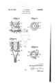
- Fig. 1 is a view, in section, of a form of sludge separator
- Fig. 2 shows a plan view of the separator shown in Fig. 1;
- FIG. 3 is a view, in section, of a modified form of sludge separator
- Fig. 4 shows a plan view of the separator shown in F18. 3.
- the separator is shown as a circular sludge collecting tank iii.
- a conduit H which receives its supply of dust bearing water, or other liquid, in the form of a slurry from a dust collector feeds into the sludge collecting tank l8 tangentially of the side wall of the tank. This slurry feeds into the tank with a whirling motion whereupon the dust therein settles to the bottom forming a sludge.
- the sludge tank is provided with a frustro-conical balil it near its top and above the water inlet.
- the baflle l8 extends downwardly and inwardly to direct the flow of dust bearing liquid toward the bottom of the tank.
- a de-watering tank l9 Concentrically located within the sludge tank i6 is a de-watering tank l9 which is supported by means of braces 26 extendingradially inwardly from the lower rim of the name 8.
- the dewatering tank i9 is circular and provided with an inverted conical-shaped bottom. The top of this tank extends above the lower rim of the baflle la.
- the tank is is further provided with an outlet conduit 2
- a plunger 25 carried by a. rod 26 is mounted withinthe pipe 23 and is adapted to force sludge from the free end thereof.
- the plunger mechanism is operated by fluid pressure'means 21 shown generally.
- the outlet end of the sludge removal pipe is provided with a pivotally mounted gate 28.
- dirt bearing liquid is fed by the conduit l1 through the inlet in the sludge tank i6.
- This slurry enters the sludge tank tangentially to the side wall and is directed downwardly with a whirling motion by the balile l8.
- the dirt in the water, or other liquid settles to the bottom of the tank where it forms'a sludge which is deposited in the sludge removal pipe 23.
- the clear liquid rises along the side wallof the tank l9,
- the separator is shown as acircular tank 28 having an inverted conlcal shaped bottom 30.
- a conduit 3,! which receives its supply of dust bearing liquid from the dust collector 3
- the slurry enters the tank with a whirling motion whereupon the dust settles to the bottom, forming a sludge.
- the sludge tank 28 is provided with a frustro-conical ballle 82 near its top and above the slurry inlet.
- baffle 32 extends downwardly and inwardly to direct the flow of dust bearing liquid toward the bottom of the tank 30 and away from the path of the clear liquid.
- a dewatering tank 33 is concentrically located within the sludge tank and is supported by means of braces 34 extending-radially inwardly from the side Wall of the sludge tank 29.
- the tank 33 is circular and is provided with an inverted conical-shaped bottom 38. The top of the tank 33 extends above the bathe-32.
- the tank 33 is further provided with a plurality of ballles 36 which are circular in shape and at-.
- baliles extend downwardly and away from the side wall 2 o! the do wi'itering tank It.
- the tank II is provided with an outlet :1 at the apex of its conical bottom to whichis connected an outlet conduit 38 which leads to a liquid pump.
- the sludge tank I! is provided at its bottom with asilldge cock 3! to permit periodic removal of sludge which collects.
- a blow-out pipe 40 is provided near the slu ge cook 39 to direct an air blast through thesludge and the outlet to facilitate removal sludge.
- dirt bearing liquid is fed irom conduit II into the sludge tank II through the side wall and tangentially thereoi.
- the slurry enters the sludge tank with a whirling motion by virtue of the tangential inlet and is directed downwardly and away from the flow oi! clear liquid by the sludge tank baille 32.
- the dirt or dust in the liquid settles to the bottom of the sludge tank 3
- Clear liquid rises adjacent the side wall of the tank 33 passing between the side wall of the tank 33 and the baille l2, whereupon it overflows into the de-watering liquid.
- a sludge separator comprising in combina tion, a main tank provided with a tangential inlet at the side through which slurry enters tangentially to the side wall of the tank and an outlet at the bottom tor the removal of sludge, a second tank open at the top supported in spaced relationship to. and within said main tank, the wall of said second tank extending below and above said inlet but not above the wall of the main tank. a bave means attached over substantially the entirecircumierence or the inner wall of the main tank above said inlet, the free edge of said means extending downwardly and away irom said wall to a point below the top of said second tank, and means for removing clear liquid from said second tank.
- a sludge separator comprising in combination. a main tank provided with a tangential inlet at the'side through which slurry enters tanaasaoao gentially to the side wall of the tank and an outlet at the bottom for the removal of sludge, a second tank open at the top and supported in spaced relationship to and within said main tank, the wall of said second tank extending below and above said inlet but not above the wall of the main tank, an annular baflle attached to the inner wall of said main tank above said inlet, the free edge of said baille extending downwardly and away from said wall to a point below the top of said second tank, and means for removing clear liquid from said second tank.
- a sludge separator comprising in combination, a main tank provided with a tangential inlet at the side through which slurry enters tangentially to the side wall 0! the tank and an outlet at the bottom for the removal of sludge, a second tank open at the top supported in spaced relationship to and within said main tank, the wall of said second tank extending below and above said inlet but not above the wall of the main tank, a baiiie means attached over substantially the entire circumference of the inner wall of the main tank above said inlet, th'ei'ree edge of said means extending downwardiyand away from said wall to a point below the top 01' said second tank, another ballle means attached over substantially the entire circumference oi the outer wall of said second tank below said inlet.
- a sludge separator comprising in combination, a main tank provided with a tangential inlet at the side through which slurry enters tangentially to the side wall of the tank and an outlet at the bottom for the removal oi. sludge, a second tank open at the top and supported in spaced relationship to and within said main tank, the wall of said second tank extending below and above said inlet but not above the wall of the main tank, an annular baflie attached to the inner wall ofsaid main tank above said inlet, the free edge 0!
- said baiiie extending downwardly and away from said wall to a point below the top of said second tank, another annular baiiie attached to the outer wall of said second tank below said inlet. the free edge of said second bailie extending downwardly and away from the wall of said second tank, and means for removing clear liquid 'rom said second tank.
Landscapes
- Chemical & Material Sciences (AREA)
- Chemical Kinetics & Catalysis (AREA)
- Separation Of Solids By Using Liquids Or Pneumatic Power (AREA)
Description
Oct. 14, -1941 F: FISHER SLUDGE SEPARATOR Fi led July 2:5} 1957 Patented Oct. 14, 1941 UNITED STATES PATENT. a ms:-
7 SLUDGE snrana'ron.
' Ernest r. Fisher, Springfield, m.
Application July 23, 1937, Serial No. 155316 4 Claims. (c1, 210-58) a a sludge separator that is simple in construction,
economical to manufacture, and efficient in operation.
Another object is to provide a sludge separator that is adapted to separate water, or other liquid, from sludge in an effective mannerand in a minimum of time.
A further object is to provide a sludge separator comprising means for readily removing the deposit of heavy sludge or sediment which is formed adjacent the bottom of the separator.
Other objects and advantages will become ap- The sludge tank It is provided st its bottom with a diametrically located pipe 23 extending through the side walls of thetank l6 at both. sides parent in the specification which follows and the disclosure of the drawing, wherein- Fig. 1 is a view, in section, of a form of sludge separator;
Fig. 2 shows a plan view of the separator shown in Fig. 1;
- bottom of the sludge tank, l6 and in the sludge I Fig. 3 is a view, in section, of a modified form of sludge separator; and
Fig. 4 shows a plan view of the separator shown in F18. 3.
In Fig. 1, the separator is shown as a circular sludge collecting tank iii. A conduit H which receives its supply of dust bearing water, or other liquid, in the form of a slurry from a dust collector feeds into the sludge collecting tank l8 tangentially of the side wall of the tank. This slurry feeds into the tank with a whirling motion whereupon the dust therein settles to the bottom forming a sludge. The sludge tank is provided with a frustro-conical balil it near its top and above the water inlet. The baflle l8 extends downwardly and inwardly to direct the flow of dust bearing liquid toward the bottom of the tank. Concentrically" located within the sludge tank i6 is a de-watering tank l9 which is supported by means of braces 26 extendingradially inwardly from the lower rim of the name 8. The dewatering tank i9 is circular and provided with an inverted conical-shaped bottom. The top of this tank extends above the lower rim of the baflle la. The tank is is further provided with an outlet conduit 2| located atthe apex of its conical bottom.
' upper side thereof and having a cut-away portion-2lin its to receive sludge as it forms. A plunger 25 carried by a. rod 26 is mounted withinthe pipe 23 and is adapted to force sludge from the free end thereof. The plunger mechanismis operated by fluid pressure'means 21 shown generally. The outlet end of the sludge removal pipe is provided with a pivotally mounted gate 28.
In operation, dirt bearing liquid is fed by the conduit l1 through the inlet in the sludge tank i6. This slurry enters the sludge tank tangentially to the side wall and is directed downwardly with a whirling motion by the balile l8. The dirt in the water, or other liquid, settles to the bottom of the tank where it forms'a sludge which is deposited in the sludge removal pipe 23. The clear liquid rises along the side wallof the tank l9,
passing between the side wall of this tank 19 and the lower rim of the bafile l8 and overflows into the tank IS. The clear liquid which collects in the tank 19 passes into the conduit 2| to be withdrawn by a pump and recirculated through the dust collector. The sludge which collectsin the removal pipe 23 may be removed periodically by opening the outlet gate 28 and operating the fluid pressure means 21 to force the plunge 25 through pipe 23 and expel the sludge. f
In Fig. 3,the separator is shown as acircular tank 28 having an inverted conlcal shaped bottom 30. A conduit 3,! which receives its supply of dust bearing liquid from the dust collector 3|, feeds into the tank 29 tangentially of the side wall of the tank. The slurry enters the tank with a whirling motion whereupon the dust settles to the bottom, forming a sludge. The sludge tank 28 is provided with a frustro-conical ballle 82 near its top and above the slurry inlet. The
baffle 32 extends downwardly and inwardly to direct the flow of dust bearing liquid toward the bottom of the tank 30 and away from the path of the clear liquid. A dewatering tank 33 is concentrically located within the sludge tank and is supported by means of braces 34 extending-radially inwardly from the side Wall of the sludge tank 29. The tank 33 is circular and is provided with an inverted conical-shaped bottom 38. The top of the tank 33 extends above the bathe-32.
The tank 33 is further provided with a plurality of ballles 36 which are circular in shape and at-.
tached to the side wall thereof. These baliles extend downwardly and away from the side wall 2 o! the do wi'itering tank It. The tank II is provided with an outlet :1 at the apex of its conical bottom to whichis connected an outlet conduit 38 which leads to a liquid pump.
The sludge tank I! is provided at its bottom with asilldge cock 3! to permit periodic removal of sludge which collects. A blow-out pipe 40 is provided near the slu ge cook 39 to direct an air blast through thesludge and the outlet to facilitate removal sludge.
In operation, dirt bearing liquid is fed irom conduit II into the sludge tank II through the side wall and tangentially thereoi. The slurry enters the sludge tank with a whirling motion by virtue of the tangential inlet and is directed downwardly and away from the flow oi! clear liquid by the sludge tank baille 32. The dirt or dust in the liquid settles to the bottom of the sludge tank 3| with theassistance oi the tank baiiies 36 and forms a sludge. Clear liquid rises adjacent the side wall of the tank 33 passing between the side wall of the tank 33 and the baille l2, whereupon it overflows into the de-watering liquid.
What I claim is:' 1. A sludge separator. comprising in combina tion, a main tank provided with a tangential inlet at the side through which slurry enters tangentially to the side wall of the tank and an outlet at the bottom tor the removal of sludge, a second tank open at the top supported in spaced relationship to. and within said main tank, the wall of said second tank extending below and above said inlet but not above the wall of the main tank. a baiile means attached over substantially the entirecircumierence or the inner wall of the main tank above said inlet, the free edge of said means extending downwardly and away irom said wall to a point below the top of said second tank, and means for removing clear liquid from said second tank.
2. A sludge separator comprising in combination. a main tank provided with a tangential inlet at the'side through which slurry enters tanaasaoao gentially to the side wall of the tank and an outlet at the bottom for the removal of sludge, a second tank open at the top and supported in spaced relationship to and within said main tank, the wall of said second tank extending below and above said inlet but not above the wall of the main tank, an annular baflle attached to the inner wall of said main tank above said inlet, the free edge of said baille extending downwardly and away from said wall to a point below the top of said second tank, and means for removing clear liquid from said second tank.
3. A sludge separator comprising in combination, a main tank provided with a tangential inlet at the side through which slurry enters tangentially to the side wall 0! the tank and an outlet at the bottom for the removal of sludge, a second tank open at the top supported in spaced relationship to and within said main tank, the wall of said second tank extending below and above said inlet but not above the wall of the main tank, a baiiie means attached over substantially the entire circumference of the inner wall of the main tank above said inlet, th'ei'ree edge of said means extending downwardiyand away from said wall to a point below the top 01' said second tank, another ballle means attached over substantially the entire circumference oi the outer wall of said second tank below said inlet. the free edge 01 said second ballle means extending downwardly and away irom the Wall of said second tank, and means for removing clear liquid from said second 4. A sludge separator comprising in combination, a main tank provided with a tangential inlet at the side through which slurry enters tangentially to the side wall of the tank and an outlet at the bottom for the removal oi. sludge, a second tank open at the top and supported in spaced relationship to and within said main tank, the wall of said second tank extending below and above said inlet but not above the wall of the main tank, an annular baflie attached to the inner wall ofsaid main tank above said inlet, the free edge 0! said baiiie extending downwardly and away from said wall to a point below the top of said second tank, another annular baiiie attached to the outer wall of said second tank below said inlet. the free edge of said second bailie extending downwardly and away from the wall of said second tank, and means for removing clear liquid 'rom said second tank.
ERNEST F. FISHER.
Priority Applications (1)
| Application Number | Priority Date | Filing Date | Title |
|---|---|---|---|
| US155316A US2259029A (en) | 1937-07-23 | 1937-07-23 | Sludge separator |
Applications Claiming Priority (1)
| Application Number | Priority Date | Filing Date | Title |
|---|---|---|---|
| US155316A US2259029A (en) | 1937-07-23 | 1937-07-23 | Sludge separator |
Publications (1)
| Publication Number | Publication Date |
|---|---|
| US2259029A true US2259029A (en) | 1941-10-14 |
Family
ID=22554943
Family Applications (1)
| Application Number | Title | Priority Date | Filing Date |
|---|---|---|---|
| US155316A Expired - Lifetime US2259029A (en) | 1937-07-23 | 1937-07-23 | Sludge separator |
Country Status (1)
| Country | Link |
|---|---|
| US (1) | US2259029A (en) |
Cited By (3)
| Publication number | Priority date | Publication date | Assignee | Title |
|---|---|---|---|---|
| US2790554A (en) * | 1955-01-18 | 1957-04-30 | Borg Warner | Separating device |
| US2921684A (en) * | 1955-10-27 | 1960-01-19 | Baker Frank | Whirlpool separator |
| US2967617A (en) * | 1958-03-14 | 1961-01-10 | American Agricultural Chem Co | Hydraulic classifier |
-
1937
- 1937-07-23 US US155316A patent/US2259029A/en not_active Expired - Lifetime
Cited By (3)
| Publication number | Priority date | Publication date | Assignee | Title |
|---|---|---|---|---|
| US2790554A (en) * | 1955-01-18 | 1957-04-30 | Borg Warner | Separating device |
| US2921684A (en) * | 1955-10-27 | 1960-01-19 | Baker Frank | Whirlpool separator |
| US2967617A (en) * | 1958-03-14 | 1961-01-10 | American Agricultural Chem Co | Hydraulic classifier |
Similar Documents
| Publication | Publication Date | Title |
|---|---|---|
| US2689017A (en) | Surface drain | |
| US3200568A (en) | Flash separator | |
| US2058044A (en) | Separator for removing oil from water, sand, and gravel | |
| US3151961A (en) | Vortex-type de-aerator and strainer | |
| US2762451A (en) | Blow-down separator | |
| GB533235A (en) | Improvements in or relating to method of and apparatus for separating undesired particles from a liquid suspension | |
| US1863111A (en) | Oil and gas separator | |
| US2756837A (en) | Liquid and gas separator | |
| US2580317A (en) | Purger | |
| US2191190A (en) | Separator | |
| US2489903A (en) | Flash chamber | |
| US2777533A (en) | Oil and gas separator | |
| US3171807A (en) | Liquid separating apparatus | |
| US2259034A (en) | Gas washer | |
| US2259029A (en) | Sludge separator | |
| US2732909A (en) | Scrubber pukifier | |
| US2361577A (en) | Apparatus for separating oil from water contaminated therewith | |
| US2277651A (en) | Air eliminator for surface condensers | |
| US2259032A (en) | Gas washer | |
| US1994110A (en) | Oil and gas separator | |
| US1916065A (en) | Combination separator | |
| US2465021A (en) | Oil cleaner | |
| RU56208U1 (en) | GAS-LIQUID SEPARATOR | |
| US2223652A (en) | Oil separator | |
| US2259030A (en) | Wet dust collector and air washer |