US2256283A - Fluid pressure brake - Google Patents
Fluid pressure brake Download PDFInfo
- Publication number
- US2256283A US2256283A US326352A US32635240A US2256283A US 2256283 A US2256283 A US 2256283A US 326352 A US326352 A US 326352A US 32635240 A US32635240 A US 32635240A US 2256283 A US2256283 A US 2256283A
- Authority
- US
- United States
- Prior art keywords
- valve
- chamber
- pipe
- brake
- pressure
- Prior art date
- Legal status (The legal status is an assumption and is not a legal conclusion. Google has not performed a legal analysis and makes no representation as to the accuracy of the status listed.)
- Expired - Lifetime
Links
Images


Classifications
-
- B—PERFORMING OPERATIONS; TRANSPORTING
- B60—VEHICLES IN GENERAL
- B60T—VEHICLE BRAKE CONTROL SYSTEMS OR PARTS THEREOF; BRAKE CONTROL SYSTEMS OR PARTS THEREOF, IN GENERAL; ARRANGEMENT OF BRAKING ELEMENTS ON VEHICLES IN GENERAL; PORTABLE DEVICES FOR PREVENTING UNWANTED MOVEMENT OF VEHICLES; VEHICLE MODIFICATIONS TO FACILITATE COOLING OF BRAKES
- B60T13/00—Transmitting braking action from initiating means to ultimate brake actuator with power assistance or drive; Brake systems incorporating such transmitting means, e.g. air-pressure brake systems
- B60T13/10—Transmitting braking action from initiating means to ultimate brake actuator with power assistance or drive; Brake systems incorporating such transmitting means, e.g. air-pressure brake systems with fluid assistance, drive, or release
- B60T13/58—Combined or convertible systems
- B60T13/62—Combined or convertible systems both straight and automatic
-
- B—PERFORMING OPERATIONS; TRANSPORTING
- B61—RAILWAYS
- B61H—BRAKES OR OTHER RETARDING DEVICES SPECIALLY ADAPTED FOR RAIL VEHICLES; ARRANGEMENT OR DISPOSITION THEREOF IN RAIL VEHICLES
- B61H9/00—Brakes characterised by or modified for their application to special railway systems or purposes
- B61H9/006—Brakes for locomotives
Definitions
- This invention relates to fluid pressure brake equipment for railway locomotives, and more particularly to the combined automatic and straight air type of locomotive equipment embodying means controlled by the engineer and by tr'aflic or signal conditions on a railway sys tem for'controlling the brakes on the locomotive and cars oia train.
- the principal object of the invention is to provide an improvedbrake equipment of the above type.
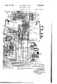
- Figs. 1, 1A and 1B represent a diagrammatic viewmainIy in section, oi a locomotive brake equipment embodying the invention
- Fig. 2 is a diagramamtic sectional view of a portion of the apparatus shown in Fig. 1A and with the parts in a diiierent position
- Fig. 3 is a diagrammatic development view of arotary valve and rotary valve seat of a brake valve device shownin Fig. 1
- Fig. 4 is a diagrammatic'development view of three cams employed in the independent brake valve device shown in Fig. 1, these cams being arranged in projected relation to the various operating positions bi said device
- Fig. 5 is a diagrammatic view of a double heading cock shown in Fig. 1A and with -the parts in a different position.
- the locomotive brake equipment comprises an automaticbrake valve device I, an independent brake valve device 2, a master switch device 3 and an application and release magnet valve device 4 controlled by said switch device, a pneumaticbrake controlling valve device 5, a relay valve device 6, an automatic train control device 1, a timing valve device 8, a brake pipe vent valve device 9, an interlock valve device Ill, a cut-oil'- valve device II, a deadmans foot valve device I2, a double heading cock l3, and,a selector cock H.
- the brake equipment further comprises a brake t to rotary valve valve device 6 for controlling the brakes on the locomotive, and still further, there are provided a plurality of difierent reservoirs ⁇ double check valve devices etc., which will be brought out in the description to follow.
- the automatic brake valve device I which is provided for the engineer to control the .brakes on the locomotive and cars of a train either by straight air through the straight air pipe It or automatically through the medium of brake pipe I5, is substantially the same as that disclosed in Patent 2,106,483 issued to Ellis E. Hewitt on January 25, 1938. Accordingly, only those parts ofthe automatic brake valve device I are shown in the drawings which are essential to the operation and aclear understanding of the present invention.
- the automatic brake valve device I comprises a pipe bracket 20 upon which is mounted a rotary valve casing section 2
- has a chamber 24 which is connected through a passage 25 containing a ball check valve 26 to a feed valve pipe 21 which is adaptedto be supplied withxfiuid under pressure from a main reservoir 28 by operation of a feed valve device 29.
- the main reservoir is adapted to be supplied-with fluid under pressure in the usual manner and the feed valve device 29 is adapted to reduce .said pressure to that desired to be carried in the brake pipe l5 and to supply fluid at this reduced pressure through pipe 21 chamber 24 in the brake valve device I. I r
- a rotary valve 30 In chambers 24 there isprovided a rotary valve 30 and extending into said chamber and having driving engagement with said valve is an operating shaft 3
- the rotary cylinder device I9 under the control of the relay valve 30 is provided to control the brakes on the locomotive and a train on the usual automatic principle through brake pipe l5 and accordingly is rotatable by the engineer to a'number of different control positions, namely, release position, first service position, lap position, service position, and an emergency position as illustrated in Fig. 3 of the drawings.
- the shaft 32 extends into the lower end of a sleeve 34 which at one end is Journaled in the brake valve casing, said sleeve having a driving connection with said shaft.
- the opposite end of sleeve 34 is Journaled in a suitable bearing provided in a bracket 35 extending from the brake valve casing.
- bracket 35 and the top of the brake valve casing the sleeve 34 is provided with a pair of oppositely arranged openings through the sides thereof and secured to said sleeve and extending across the openings at one side of the sleeve is a pin 35.
- a plunger 38 is slidably mounted in sleeve 34 beneath the brake valve handle 33 and is urged into engagement with said handle by a spring 33.
- a plunger 43 is slidablymounted in the sleeve 34 above the handle 33 and is provided with an upwardly extending pin 4
- the valve42 is contained in a chamber 43 which is connected to a passage 44 and which contains a spring 45 acting on said valve for urging it to its seated position shown.
- the spring 45 is adapted to seat the valve 42.
- the spring 39 is adapted to rotate said handle about the pin in a clockwise direction for urging the plunger 43 in an upwardly direction to move the valve 42 away from the seat so as to connect chamber 43 to a chamber within the plunger,
- the fit between the side openings in sleeve 34 through which the handle 33 extends and said handle is such that upon movement of the handle in a horizontal plane the sleeve and thereby the shaft 32 will be turned with the handle.
- a poppet valve 43 having a fluted stem 49 which extends through a suitable bore in the casing for engagement by a cam 53 formed on the exterior of sleeve 34, this sleeve cam being so designed as to unseat said valve whenever the brake valve handle 33 is in positions corresponding to the release and first service positions and to permit closure of the'valve in all other positions of the handle.
- the valve 43 is contained in a chamber 5
- acts on valve 43 for urging it to its seat.
- a selector handle which is movable to either astraight air brake controlling position or to an automatic brake controlling position for selecting whether the brakes on the 10-- comotive and train will be controlled by straight air by operation of the straight air application and release valve portion 23 or automatically by operation of the rotary valve 33.
- is disconnected by means (not shown) from the handle shaft 32 so that the rotary valve 33 will remain in its release position shown upon operation of the brake valve handle 33, while if the selector handle 55 is in condition and the parts thereof remaining in their release position.
- the straight air application and release valve portion 23 of the brake valve device is provided for varying the pressure in a straight air control pipe 55.
- the pipe 55 In the release position of handle 33 the pipe 55 is adapted to be vented for eifecting the release of brakes on the locomotive and train.
- an application of the brakes is effected by moving the brake valve handle 33 to any desired position in an application zone (not indicated) whereupon the straight air control pipe 55 is disconnected from the atmosphere and fluid is supplied to said pipe to a degree dependent upon the extent of movement of said handle into said zone.
- a release of a straight air application of brakes is effected by return of the handle, 33 to the release position.
- the independent brake valve device 2 is similar to that disclosed-in our PatentqNo. 2,173,940, is-
- This handle extends through suitable slots provided in the opposite sides of sleeve 53 and the end of the handle is pivotally connected to a pin 52 carried by said sleeve, the sides of said slots cooperating with the handle to eilect rotation of the sleeve 53 and thereby shaft 53 and cam sleeve 53 upon movement of the'handle 3
- a plunger 53 is slidably mounted in sleeve 53 beneath the handle 5
- the cam sleeve 53 is provided at its lower end which is operative by said plunger upon movement in the directionof the right hand to supply fluid to chamber 51 at a pressure depending upon the extent of such movement.
- the operation of the release valve mechanism 14 is adapted to reduce the pressure in chamber 51 to a degree dependent upon the extent of such movement.
- the self-lapping ap- 9,956,293 'cation delay valve I8 said stem extending through a suitable slot provided in the lower end of said sleeve.
- the application delay valve I8 is contained in a chamber I9 and a spring 80 in said chamber acts on said valve i'or urging it toward its seat.
- the delay valve I8 is provided for controlling communication between the chamber I9 and an atmospheric port 8
- Fig. 1 the independent brake valve handle GI and other parts of the independent brake valve device, just described, are shown in their release position, which they normally occupy.
- is movable from the release position in one direction into an application and release zone,-shown in Fig. 4, for operating the self-lapping straight air application and release valve mechanism I4 to supply fluid to chamber application and release valve mechanism'14 is adapted to operate to vent fluid under pressure from the chamber 51 to an extent depending upon the position of the handle with respect to. 'therelease position, and at the time the release position is obtained said mechanism is adapted to provide for a complete venting of the chamber 51.
- I2 for operating the plunger I3 is designed, as shown in Fig. 4, to vary the position of said plunger in accordance with the position of the brake valve handle.
- the handle 61 is movable in the opposite direction from release position to a locking posi- To accomplish this operation the cam.
- the master switch device 3 comprises a casing containing two flexible diaphragms 93 and 94 operatively connected together by' a stem 95.
- the diaphragm 93 has at its outer face a chamber 96 connected to a pipe 91 while the diaphragm 94 has at its outer face a chamber 98 connected to a straight air pipe I6 through a choke 99 and a parallel arranged check valve device I80.
- a chamber II is formed intermediate the diaphragms, and secured to but insulated from the stem 95 in this chamber is a movable contact I02 to which is connected one terminal of an electric supply such as a battery I03, th'eother terminal of which is. grounded.
- the contact fingers I84 and I05 are connected, respectively, to the release and application train wires I8 and II.
- the application and release magnet valve device 4 comprises an application magnet III) having one terminal connected to the application train wire I! and the other to ground, and a release magnet III having one terminal connected to the release 'train wire I8 and the other to to the straight air pipe I 6.
- a spring II5 acts on tion indicated in Fig. 4, and it will be apparent from the-development of the cams that the delay valve I8 and the cut-off valve 68 will both be closed in the locking position.
- a bail 82 over which the handle is adapted to turn upon movement to its different positions.
- the ball 82 is pivoted on a pin 83 in the casing of the brake valve device, and at a point remote from said pin is supported on a plunger 84 which is slidably mounted in the brake valve casing.
- plunger 84 iscarried by a spring 85 supported on avalve 86 which is contained in a chamber' 81 open to the atmosphere through a vent port 88.
- the valve 86 has a fluted stem slidably mounted to a suitable bore in the casing and extending into a chamber 89 where it engages the fluted stem of an oppositelydisposed valve 90 contained in a chamber 9
- acts on the valve 98 for normally urging it to its seated position and for unseating the valve 86, as shown, and is ofsufiicient strength to normally support the plunger 84 and hail 82 in the position shown throughthe medium of spring 85.
- the handle BI is adapted to be turned on pin 82 against the pressure of spring 64 on plunger 63 in a downwardly direction into engagement.
- the release magnet III is provided for seating a release valve II6 upon energization of the magnet to close communication between the straight air branch pipe 4 and an atmospheric port II I.
- a spring H8 acting on valve I I8 is provided for unseating said valve upon deenergization of magnet valve I I I, to thus open communication between the straight air pipe and the atmospheric port I".
- the brake controlling valve device 5 comprises a pipe bracket I20, an emergency valve device mounted on ,one face of the pipe bracket and adapted to be controlled by variations in pressure in brake pipe IS, a filler piece I22 mounted on the opposite face .of said bracketand a service application valve device I23 mounted on said filler piece and also adapted to be controlled by variations in pressure in the! brake pipe I5.
- This brake controlling valve device may be similar to';that disclosed in our Patent 2,173,940 issued September 26, 1939, and the description thereof will therefore be limited ,to only those parts which are /required to'bring out clearly the .present invention.
- valveidevice I23 is adapteclfto operate upon a reduction in brake pipe pressure at either a service or an emergency rate to supply fluid under pressure from the of brakes on the locomotive as it is adapted to operate upon an increase in pressure in the brake pipe to vent fluid under pressure from said passage for effecting a release of brakes and to also supply fluid under pressure from the brake pipe to the auxiliary reservoir III and to an emergency reservoir I28 by way of a passage I21 for charging same.
- Thisoperation of a valve device 4 of this type is well known.
- the reference numeral I25a indicates a portion of the main slide valve in said device in its normal or release position.
- the slide valve I25a Upon an emergency reduction in pressure in the brake pipe I5 the slide valve I25a is adapted to be moved to an emergency position in which a cavity I26 in said valve will connect passage I21 communicating with the emergency reservoir I28 to passage I25 to which, in efiecting an emergency application of the brakes, fluid under pressure is also supplied by the service application valve device I23.
- An emergency choke I32 is provided to control the rate of flow of fluid under pressure from the emergency reservoir I28 to the passage I25.
- auxiliary reservoir H3 and emergency reservoir I28 Fluid under pres-- sure will thus be supplied from both the auxiliary reservoir H3 and emergency reservoir I28 to passage 125 through the service and emergency chokes I24 and I32, respectively, for effecting an emergency application of the brakes on the locomotive.
- the cavity I26 in the emergency slide valve I25a in its emergency position also connects the emergency reservoir passage I21 to a passage I30 for reasons which will be later brought out, it being noted that in the release position of the slide valve I25a the cavity I26 therein connects the passage I30 to an atmospheric vent port I3I.
- the filler piece I22 carries on one face an interlock valve device I35 for interlocking the automatic and straight air control of the brakes on the locomotive and the independent control of the brakes of the locomotive, and carried on another face of said filler piece is an emergency application delay valve device I36.
- the interlock valve device I35 comprises two double check valves I31 and I38 of usual construction. a selector valve device I38 and a release valve I 40.
- slide valve I42 is contained in a chamber I44 formed at one side of the piston, which chamber is connected by a passage and pipe I45 to a pipe I46 connected to and charged at all times with fluid under pressure from the main reservoir 28.
- the release valve I40 is preferably in the form of a valve piston slidably mounted in the casing of the interlock valve device I35 and having on one face a valve. seat arranged to seal against an annular seat rib I5I encircling a vent port I52 for closing communication between said port and a chamber I53 provided at one side of the valve piston around said seat rib. At the opposite side of the valve piston there is provided a chamber I54 containing a spring I55 acting on said valve piston for urging same in the direction of and into engagement with the seat rib I5I.
- a port phragm is provided on its opposite face with a valve 38I provided for engagement with an annular valve seat 382 to close communication between space within said seat rib whichiis cqnnected to the application and release passage 125 and an annular space encircling the seat and open to a passage 418.
- Passages I25 and 418 are in permanent communication through va restricted passage 418, and in addition there is a one-way flow release communication from passage 418 to passage I25 past a check valve I50.
- the relay valve device 6 may be of any de-- sired construction'and as shown is connected to the main reservoir pipe I46, to a pipe I51 leading to the brake cylinder device I8 and to a pipe I58 which is connected by a pipe I58 to the brake controlling valve device 5.
- fluid under pressure is adapted to be supplied through the pipes I58 and I58 to the relay valve device 6 for actuating same to supply fluid at a corresponding pressure from the main reservoir pipe I46 to the brake cylinder device I8 for applying the brakes on the locomotive, while upon the venting of fluid under pressure from the control pipe I58 the relay valve device is adapted to operate to eflect corresponding venting of fluid under pressure from the brake .cylinder device I3.
- the split reduction valve device I63 com-v prises a valve piston I slidingly mounted in the casing and having at one side a chamber I8I in constant communication with a passage I82 which leads to the seat of slide valve I1I.
- a valve piston I slidingly mounted in the casing and having at one side a chamber I8I in constant communication with a passage I82 which leads to the seat of slide valve I1I.
- an annular seat rib I83 encircling an opening I84 leading to a chamber I85 which is constantly open to the atmosphere through a vent port I86.
- a spring I81 in chamber I8l acts to urge the valve piston I88 into engagement with the seat rib I83 and in this position of said valve piston communication is adapted to be established between passage I82 and a passage I88 which is connected to a pipe I89 leading to a second reduction reservoir I 98 and to the seat of rotary valve 38 is the brake valve device I.
- a piston I92 slidably mounted in the casing is provided with a stem I93 extending through chamber I85 and opening I84 for engagement with the valve piston I88.
- One face of the piston I92 is thus open to the vented chamber I85 while at the opposite face of said piston there is provided a chamber I94 which is connected to a passage I95 leading to the seat of slide valve I1I.
- the piston I92 is provided for moving the valve piston I88 from the position shown in an upwardly direction into sealing engagement witha;
- the combined equalizer discharge valve mechanism and maintaining valve device I85 comprises an equalizing piston 2I8 having at one side a chamber 2II which is connected to a passage 2I2 leading to a passage 2I3.
- the passage 2I3 at one end is connected to a pipe 2 leading to an equalizing reservoir 2I5 while the other end of passage 2I3 terminates at the seat by guided in a suitable bore provided in the casing.
- a bell crank 228 in chamber 2I8 is rockably mounted on a pin 22I secured in the casing.
- the end of one arm of this bell crank is disposed in a recess 223 in the equalizing piston stem 2I9 for movement by and with said stem.
- a maintaining valve 224 having a stem extending into operative alignment with said arm.
- the maintaining valve 224 is contained in a chamber 225 and is provided for controlling communication between said chamber and the chamber 2I8, a spring 228 in chamber 225 acts on the valve 224 for seating same, while the equalizing piston 2I8 is operative upon movement from the normal position shown in the direction of the right hand to actuate the bell crank 2I8 to unseat said valve.
- a brake pipe discharge valve 228 slidably mounted in the casing is provided for controlling communication between chamber H8 and a brake pipe discharging passage 229, said valve being operatively connected to the other arm of the bell crank whereby upon movement of the equalizing piston 2I8 in the direction of the left hand,'as viewed in the drawing, said bell crank will unseat said valve.
- a spring 238 acting on the discharge valve 228 is provided for seating same when the bell crank 228 and equalizing piston 2I8 are in their normal positions shown, under which conditions the maintaining valve 224 is also seated by the spring 228.
- the automatic suppression valve device I88 comprises a double beat valve 233 contained in a chamber 234 and arranged to control communication between said chamber and a chamber 235 at one side of the valve and a chamber 238 at the opposite side of'the valve.
- a flexible'diaphragm 231 is provided for moving thedouble beat valve 233 from the position shown to its lower seated position.
- One face of the diaphragm 231 is open to chamber 238, while the opposite face is opento a chamber 238.
- a follower 239 engaging thediaphragm 231 and providing an operating connection be- 1 tween said diaphragm and the double beat valve 233.
- a spring 248 in chamber 235 acts ,on the valve 242 through the medium of a follower 249 and has at its opposite face a chamber 258.
- acting- .on the double beat valve 242 for normally maintaining said valve in the position shown.
- The; straight air suppression valve device I81 comprises a double beat valve 252 contained in a chamber 253 which is connected by a passage 254 to chamber 235 in the automatic suppression valve device I88.
- the valve 252 is provided to control communication between chamber 253 and a chamber 255 on the one hand, and between the a chamber 253 and a chamber 258 on the other hand.
- chamber 258 there is provided a plunger 251 which is subject to the pressure of a spring 258, said plunger being adapted to be operated by said spring to urge said valve to the normal position shown.
- the chamber 255 is provided at one side of a flexible diaphragm 259 having at the opposite side a chamber 288, said diaphragm being operatively connected through the medium of a follower 28I .to the double beat valve 252 for moving said double beat valve to a seated position opposite to that shown.
- the straight air suppression valve device further comprises a valve piston 285 slidably mounted in the casing and having at one side a chamber 288 which is in constant communication with the atmosphere through a vent port 281.
- the valve piston 285 has at the opposite side a chamber 288 connected by a passage 289 to a diaphragm chamber 288.
- the valve piston 285 is provided in chamber 288 with a coaxially arranged valve 218 of smaller diameter than that of the valve piston and arranged to engage a.
- valve piston 265 is adapted to be moved from the position shown against the opposing pressure of spring 213 into sealing engagement with a gasket 216 for unseating the valve 210 and for at the same time closing communication between the chambers 268 and 266, all of which will be hereinafter fully described.
- the timing valve device 8 comprises a magnet 280 which is adapted to be controlled by any suitable means (not shown) which are operative in response to favorable and unfavorable track signals on a railway.
- the magnet 280 is adapted to be energized and when unfavorable deenergized.
- the magnet 280 is provided for controlling a pair of valves 28l and 282 which are coaxially arranged and movable together.
- the valve 28! is contained in a chamber 283 which is at all times open to the atmosphere through a vent passage 284, said valve being provided to control communication between said chamber and a chamber 285.
- the valve 282 is contained in a chamber 286 which is connected to a Pipe 281 leading to a feed valve device 288 which is adapted to operate to supply fluid from the main reservoir to the pipe 281 at a pressure desired for control of the timing valve device.
- the valve 282 is provided for controlling communication between the chamber 286 and the chamber 285.
- a spring 289 in chamber 286 acts on the valve 282 for seating same and for at the same. time unseating valve 28i upon deenergization 01' magnet 280.
- the timing valve device 8 further comprises a doublebeat valve 292 containedin a chamber 293 which is connected by passage and'pipe 294 to chamber 256 in the straight air compression valve device I61.
- the valve 292 is provided with a fluted stem 295 which extends into a chamber 296 connected with the pipe I18 and is also provided with another fluted stem'300 oppositely arranged and extending into a chamber 291 which is constantly open to the atmosphere through a vent port 298..
- the chamber 291 is provided at one side of a valve piston'299 which is operatively connected to the valve stem 300 through a spring 30!.
- valve piston 299 At the opposite face of the valve piston 299 there is provided a chamber 302 in constant communication with a timing reservoir 303 and also connected by way of passages containing a choke 304 and a check valve 305 to the chamber 285.
- annular seat rib 306 On the face of valve piston 299 open to chamber'302 there is provided an annular seat rib 306 of smaller diameter than that of the valve piston and which is adapted to eiiect sealing engagement with a gasket 301 in the lower position of the valve piston, the space outside of said rib being open to the atmosphere through a groove 308 by-passing the valve piston and connected to the chamber 291 under this condition.
- a spring 309 for moving the valve piston 299 to its lower position, under which condition a spring 3H1 in chamber 296 is adapted to move the double beat valve 292 from its normal position shown to a lower seated position for closing communicationbetween chambers 293 and 291 and for opening communication between chamber 293 and chamber 296.
- annular chamber 324 which, with the pistons in the position shown, is connected adjacent the piston 3l6 to a pipe 325 leading to the brake pipe 15.
- 5 is connected to the passage and pipe 2l8 leading to chamber H6 in the combined equalizing discharge valve mechanism and maintaining valve device and also to chamber 203 in the cut-ofi valve device I64.
- the pistons 3L5 and 3l6 are adapted to be moved from the position shown in an upwardly direction to a brake pipe venting position defined by engagement of the piston 3l'5 with a gasket 326 and in which position the piston 3i6 is adapted to be disposed above the passage 325 so as to connect said passage to chamber 322 and thereby to the atmospheric vent port 323..
- chamber 3l8 there is 'a spring 321 acting on the pistons 3l5 and 3l6 for urging and normally holding said pistons in the lower position shown.
- the interlock valve device l0 comprises 9. casing containing two spaced flexible diaphragms 330 and 33l. area than diphragm 33l and has at its outer face a chamber. 332 connected to a pipe 333 to which is also connected atiming reservoir 334, while the diaphragm 33! has at its outer face a chamber 335 which is connected to a pipe 336 through achoke 331 and a check valve 338 and which contains a spring 339 acting on the diaphragm.
- vent valve 3 for controlling a vent valve 3 slidably mounted in a suitable bore in the casing for controlling communication between the passage 3i9 and a vent port 342 which is open to the atmosphere through a chamber 343 formed intermediate the diaphragms and an atmospheric passage 344.
- the vent valve 341 has a stem telescopically connected to the stem of a plunger 345 by means of a pin and slot connection 346, and a spring 341 is interposed between said valve and plunger for normally urging same apart.
- the plunger 345 is engaged by an extension of one end of the yoke 340 and is operative thereby upon movement of said yoke towards the left hand to seat the valve 3 whileupon movement toward the right hand the valve is relieved of seating pressure to permit same to be opened by pressure of fluid from
- the diaphragm 330 is of smaller of the larger diaphragm 352;
- is provided to control communication between the pipes I18 and .358 and is normally spaced from a seat rib 353 to open said communication andis adapted to be moved into munication upon the supply of fluid under pressure to a chamber 354 provided at the outer face
- the chamber 354 is normally open to the atmosphere through a port 355 which is controlled by a valve piston 356 and opened to the chamber 354 which said valve piston is in the normal position shown.
- This valve piston is subject on one face to the pressure of a spring 351 which normally urgesit to the closed position shown and on the opposite face is subject to the pressure of fluid in a chamber 358.
- the foot valve device I2 comprises a casing containing a flexible diaphragm 36I adapted to cooperate with a valve seat 362 to control communication between pipe 358 and a safety control pipe 363 leading to the safety control valve chamber 43 in the brake valve device I.
- a bellcrank 364 which is pivoted in the casing and which is provided with a horizontally extending pedal arm 365 adapted when subject to foot pressure from the locomotive engineer to move the diaphragm 36I into sealing engagement with valve seat 362 for closing communication between pipes 350 and 363.
- a spring 366 is interposed between the casing and bell crank for operating the bell crank upon the release of manual pressure thereon in a direction drawing against the opposing pressure of spring away from the diaphragm 36I to permit said diaphragm to flex away from the valve seat 362 and thereby open communication between th pipes 350 and 363.
- the double heading cock I3 is provided for cona trolling communicationthrough the pipes 325,
- a port 314 in plug valve 31I is adapted to open communication through a pipe 315 to a timing reservoir'316.
- Another port 311 in the plug valve 31I * is adapted to open communication through a pipe 318 to a suppression reservoir 319, while a port 361 insaid valve is adapted toestablish communication through pipe 21 to a pipe 368.
- a choke 319a being provided in the port 361 for limiting the rate at which fluid at feed valve pressure will be supplied from the pipe 21 to the pipe 368.
- a cavity 388 therein connects the passage 3 to a passage 389 which leads to the piston chamber 201 in the cut-off valve device I64.
- the chamber 201 is thereby charged with fluid at feed valve pressure which acting in conjunction with spring 208 on piston 200 moves said piston and thereby the cut-off valve 20I to the open position shown in the drawings.
- fluid at feed valve pressure supplied to chamber 205 flows to chamber 203 and thence in one direction through a passage 390 to chamber 241 below diaphragm 248 in the reduction insuring valve device.
- Fluid at feed valve pressure thus supplied to chamber 324 in the vent valve device 6 equalizes through .a port 393 in piston 3I5 into chamber 3I8 and thereby into pipe 3I9 leading to the in-- terlock valve device I0, the valve 3 in said interlock valve device being normally closed by the action of spring 339 on the diaphragm 33I.
- said piston and thereby the piston 3I6 are positioned as shown due to the action of spring 321 and in this position fluid at feed valve pressure supplied to chamber 324 flows into pipe 325 and thence to the brake pipe I5 for charging same on the locomotive and train.
- Fluid at feed valve pressure thus supplied to the brake pipe I5 flows therefrom to the emergency application valve device I2I and to the service application valve device I23 of the brake controlling valve device 5 on the locomotive. Both of these devices are thereby conditioned during charging of the brake pipe for operation in the well known manner upon a reduction in brake pipe pressure to apply to the brakes on the I locomotive, it being desired to point out however I that during charging of the brake pipe the service application valve device I23 operates in the usual manner to establish communications through which the auxiliary reservoir H4 and emergency reservoir I28 are charged with fluid under pressure from the brake pipe.
- a cavity 394 in rotary valve 30 connects a passage-395 which is supplied with fluid at feed valve pressure from passage 386, to a passage and pipe 396 leading to a suppression reservoir 391 and to diaphragm chamber 250 in the reduction intion, apply root pressure to the pedal 365 of the foot valve device I2 and seat the diaphragm 36I against the valve seat 322 and thereby close communication between pipes 350 and 363 and accomplish the same end as by holding the brake valve handle in a depressed condition. Either the brake valve handle 33 must be held depressed or the pedal 365 must be subjected to manual pressure according to the preference of the engineer.
- Fluid at feed valve pressure supplied to the rotary valve chamber 24 also flows through a port 399 in the rotary valve to a pipe 400 which leads to the seat of slide valve I" of the train control application valve device and in said slide valve there is provided a cavity 40I which in the release position of the valve connects the passage 400 to the passage 2I3.
- the passage 2I3 is connected by passage 2I2 to the equalizing piston chamber 2 and by pipe 2 to the equalizing reservoir 2I5 whereby said chamber and reservoir are also charged with fluid at feed valve pressure 'which leads to the seat 01 slidevalve I1I.
- 'cavity 404 inslide valve I1I connects the passage 403'to the passage and pipe318'whlch is as carried in the brake pipe I5.
- the equalizing discharge waive piston 2I0 is thus subject in chamber 2I I to equalizing reservoir pressureand:
- a first reduction limiting reservoir 408 is connected by pipes 403 and 4I0to a-pa ssage I in the brake valve device which passage islapped by the rotary valve 30;
- the secondreduction reser, Qoir I30 connected to pipe I83 is alsofnormally open, to the atmosphereby way of said pipe and a passage 1 in 504 leading to theibrake' valve device which is-open to the exhaust'c'avity 4-06in the rotary valve 30.
- diaphragm chamber 238 in the suppression valve device I68 is also normally open to the atmosphere through cavity 408 in rotary valve 30 or the brake valve device by way of passage and pipe. 4I8 connecting said chamber and cavity.
- 'A stop reservoir-420 is also at atmospheric pressure when theparts of the brake mechanism are in the release positions-above described, due
- valve chamber :8] inthe'brake valve device I and-thence past the poppet valve 48- to the atpiston I80 is normally held in its lower position by spring I81 thereby connecting passage I88 from the second reduction reservoir I80 to passage I82 which in release position-of slide valve the vented port 413.
- valve 233 in its upper position shown
- valve 210 will be seated by the action 01 spring 213 on valve piston 265; With'the' valve piston 265 in this position chamber 280 below the diaphragm 253 is open to the atmosphere through chamber-288, leakage groove 214, chamber 265 and ventport 261and this permits spring 250 acting on plunger 251 to move the double beat valve 252 to the position shown.
- Pipe I51 connected to the brake cylinder-device I8 is also connected to one-end of 'a double check valve device 431 and the opposite end of this double check valve device is connected by a pipe 'valve seat 353 and'the pipes I18 and 350 arein 438 to pipe I48 which leads to chamber 89 in the independent brake valve device and which in the release position of said brake valve device is open to the atmosphere past the lookout valve 88 and through the vent 88.
- the opposite ends of the aesacee 483 is also connected by a passage 481 and through a choke 484 with diaphragm chamber 238 in the automatic suppression valve device I48 50 that said chamber is likewise normally at atmo'spherlc pressure,
- the locomotive brake equipment is now in condition for operation to control th'e brakes on the locomotive and the cars of a train, it being noted that the handles 33 and II of the two brake valve devices are in theirbrake'release positions and that the magnet 2800! the timing valve device is energized due to the trafllc conditions or "track signals being favorable to permit movement of the locomotive.
- the selector handle 55 on the side of the brake valve device I is in the position providing for electropneumatic straight air control of the brakes on the locomotive and cars of a train by operation of the brake valve device I, under which condition the straight air application and release valve portion 23 of the brake valve device is cut in for response to operation of the brake valve handle 33 while the rotary valve will remain inthe normal release position shown. 1
- double check valve device 431 are thus both normally vented and as a result pipe 338 connected to diaphragm chamber 335 in the interlock valve device I0 will likewise be normally vented through said double check valve device and either one or the other of said pipes.
- the two diaphragm chambers 332 and 335 in the interlock valve device thus being both normally vented permits the spring 338 to hold-the vent valve 3 seated as above mentioned.
- the straight air control pipe 56 is connected to one end of the double check valve device 458, the side outlet of which is connected-to pipe. 91 leading to diaphragm chamber 86 in the master switch device 3 while the other end of this double check valve device is connected to a pipe 458 which leads to the side outlet of a double check Fluid pressure thus supplied to the straight air control pipe 58 flows tothe double check valve device 458'and through said device to pipe'81 and thence to diaphragm chamber 88 in the master K switch device 3. s
- double check valve device 480 is connected by a pipe 46I to passage I30 in the emergencywalve device I2I of the brake controlling valve device 5 which passage is normally open to the atmosphere through cavity I26 in the emergency slide valve I25 and the atmospheric passage I3I.
- Theotherend oi the double check valve device 480 is connected to a pipe 462 leading to a passage 463 in the train control application valve device and such passage is normally vented to the atmosphere through a port 464 in slide valve Ill and thence through ports 3, H4 and the atmospheric exhaust passage 4I5.
- the passage 463 is also connected by a passage 465 containing a choke 466 with diaphragm chamber 255 in the straight air suppression valve device I61 so that said chamber is also normally open to the atmosphere. The passage out the train.
- th release magnet III On the locomotive, th release magnet III is energized by the electric current supplied to wire I8 and operated to close the release valve II8, while the subsequent energization of the application magnet IIO by electric current from wire I1 acts to unseat the supply valve II2 for supplying fluid under pressure from the auxiliary reservoir II3 to the straight air pipe I8 which is connected through the train.
- Fluid pressure thus supplied to the straight air'pipe I8 on the locomotive flows therefrom to the relay valve device 6 by way of passage 433 in the brake controlling valve device 5, cavity 432 in the interlock slide valve I42, passage 43I, past the upper end of the double check valve device I38, to passage 430, thence past the upper end of the double check valvedevice I31 to passage 428 connected to pipe I59 and thence through pipe I58 t0 the relay valve device 8.
- the relay valve device is then operated by the fluid pressure supplied from the straight air pipe to supply fluidat a corresponding pressure. from the to the brake cylinder device I3 tor "actuating same in theusual manner to apply the brakes on the locomotive.
- Fluid under pressure supplied to passage 420 for eflecting operation of the relay valve device as just described also flows to chamber I53 above the release valve I40 and equalizes through port 300 in said valve into spring chamber I54 so as to permit spring, I55 to maintain said release valve in sealing engagement with the seat rib .I5l. g
- the relay valve device 6 will operate in the well known manner upon movement of the master switch devlce'3 to lap position to limit the pressure of fluid supplied to the brake cylinder I3 to adegreecorresponding to the straight air pipe pressure supplied to and controlling the operation of said relay valve device.
- the engineer desires to increase the degree of straightgair application of brakes he may operate'the brake valve handle 33 to increase the pressure of fluid in the straight air control pipe 58 and the master switch device 3 will thus operate to provide a corresponding increase in pressure in the straight air pipe I6 as will be apparent.
- the relay valve device S willthen in turn respond to provide a like increase in pressure in the brake cylinder' I9 for increasing the degree of brake application on the locomotive.
- the interlock valve device I0 will operate to efiect an emergency application of brakes on the locomotive and train in a manner which will be later brought out.
- Fluid pres ure then flows from chamber 358 to chamber 354 and this pressure acting on the diaphragm L352 moves the diaphragm 35I into sealing 'en agement with .seat rib 353 thereby closing communication between the pipes HB and 350.
- the pedal 355 of the foot valve device as well as handle 33 on the brake valve device I may then be relieved oi manual pressure, permitting commuhication to be established between pipes 350 and 363 and permitting unseating of the poppet valve 42 in the brake valve device I which thereby opens the pipe 350 to the atmosphere. Only when the cutoff valve device II is in its closed position just described can.
- valve ll permits fluid at main reservoir pressure supplied to chamber II to flow past said valve to chamber II and thence through passages and pipe I48 to the interlock piston chamber I41 in the brake controlling valve device i.
- the valve chamber I" at the opposite side of the interlock piston MI is constantly sup;
- the cavity 432 therein connects a passage 4-'II communicating with chamber I54 at thelower face or release valve I to a passage 412 which is connected by pipe and passage v413 to the poppet valve chamber 69 in the independent brake valve device I.
- the chamberfir is open past valve 68 to chamber 51, and chamber 51 is open to the atmosphere through thereby operates the straight air self-lapping application and release valve mechanism 22 to vent fluid under pressure from the straight air control pipe 56 and thereby from diaphragm chamber 96 'in the master switch device 3.
- Straight air pipe pressure acting in diaphragm chamber 98 or said switch device then moves the diaphragm 94, stem ttend.
- the engineer first moves the brake valve handle 33 to the first service position for effecting a light controlled reduction in brake pipe pressure and consequently a light application of the brakes on the train to cause agentle gathering of the slack in the train following which he may move the brake valve handle to service position for completing the reduction thereby efiecting what is cavity 40I in the application slide valv I1 I, pipe 400 leading to the rotary valve 30, a cavity 413 in the-rotary valve containing the usual service choke 413a (Fig.
- the first reduction reservoir is open to the atmosphere through the application slide valve IN by way of port containing the choke 506, but this choke is small and merely acts to continue the reduction in equalizing reservoir at a very slow rate after equalization into the first reduction reservoir at a service rate as just described.
- brake pipe pressure in chamber 2 I6 at the opposite side of the equalizing piston 2I0 effects movement of said piston in the direction of the left hand to actuate the bell crank 220 to unseat the brake pipe 1 atmosphere through passage 229, the usual serv. ice choke 414', passage 415, pipe 416, a cavity'411 T in rotary valve 30 and thence through the atmosdischarge valve 228.
- the chamber 2" being in communication with the brake pipe I5 through the vent valve device 9, the unseating of the brake pipe discharge valve 228 permits fluid un- I der pressure to flow from the brakepipe to the pheric ei'rhaust passage 401, for thereby effecting a service rate of reduction in brake pipe pressure to initiate a service application of the brakes on the locomotive and cars of the train.
- the service application valve device I23 responds to the service reduction in brake pipe pressure to supply fluid under pres-- through the restricted passage 418 to passage 419 leading to thelower face of double check valve I31 and shifts said double check valve to its upper position.
- the fluid pressure supplied to passage I19 then flows past check valve I31 to passage 429 and thence to the relay valve device 6 foroperating same to supply fluid under pressure to the brake cylinder device I9 for initiating the application of brakes on the locomotive.
- the service application valve device I23 then operates in the usual manner to limit the reduction in aux iliary reservoir pressure, due to flow to the relay valve device 6, to the same degree as the reduction in brake pipe pressure for thereby limiting the degree of brake application on the locomotive so as to cause a general gathering of the slack in the train.
- the maintaining valve will be opened by the equalizing piston M to a degree depending upon the degree of brake pipe leakage and sumbrake valve handle 33 is turned to service position in which the supply of fluid under pressure to the maintaining valve chamber 225 is cut off and in which the equalizing reservoir 2I5 and equalizing piston chamber 2 are connected to the atmosphere through pipe 400, a cavity 501 containing a service choke 503 in rotary valve and the atmospheric exhaust passage 401 and through this communication the reduction in pressure in the equalizing reservoir and equalizing piston chamber is continued until a full service reduction therein has been effected after which the brake valve handle 33 is operated to turn the rotary valve 30 to lap position to lap pipe 400 so as to prevent further and unnecessary venting of fluid under pressure from the equalizing reservoir and the equalizing piston chamber.
- the equalizing discharge valve mechanism I responds to this further reduction in equalizing reservoir pressure to effect a corresponding increased reduction in brake pipe pressure and the service application valve device I23 of the brake controlling valve device 5 on the locomotive then operates to supply fluid under pressure from the auxiliary reservoir I I3 to the relay valve device 6 as hereinbefore described to increase the degree of brake application on the locomotive to a full service degree in the usual manner.
- the interlock valve device I0 is conditioned to hold th valve 34I closed in the same manner as when an electropneumatic straight air application of the brakes is effected.
- the cut-off valve device II is also operated as hereinbefore described by fluid under pressure supplied for operating the relay valve device 6 to close communication between the pipe I18 and the pipe 350 so that the engineer may remove manual pressure from the treadle 365 of the foot valve device I2 and/or handle 33 of the brake valve device I.
- fluid under pressure supplied to the first reduction limiting reservoir 408 in effecting an automatic service application of brakes is vented. therefrom in the lap and release positions of the brake valve rotary valve 30 by way of pipe 403, port 2 in the application slide valve III, port 503, passage 504 (with said slide valve in release position), and pipe 505 which is opento the exhaust cavity 406 in the rotary valve 30 in the release position of the brake valve handle 33 and'to the vented cavity 496 in the lap positon.
- the first reduction reservoir 408 will be promptly vented while graduating a release of brakes by moving the brake valve handle 33 back and forth between the release and lap positions and thus be in condition to effect a reduction in pressure in the equalizing reservoir 2I5 in the manner hereinbefore described in case the engineer moves the brake valve handle 33 to first service positon to obtain an increase in the degree of brake application to stop the train as desired.
- the emergency application valve device I2I of saidbrake controlling valve device responds to the emergency reduction of brake pipe pressure to position the slide valve I25a in emergency position and thus connect passage I21 from the emergency reservoir I28 through cavity I26 to the application and release passage I25. Fluid under pressure then flows from the emergency reservoir to passage I25 at a rate determined by the emergency choke I32 and along with the fluid supplied from the auxiliary reservoir to said passage flows to the emergency delay valve device I36 and through choke 418 therein to passage 419 and thence to relay valve device 6 in the same manner. as in effecting a service application of the brakes.
- the relay valve device 6 is thereby operated to supply fluid to the brake cylinder device I9 at a pressure corresponding to that of the actuating fluid for thereby applying the brakes on the locomotive in emergency.
- the choke 418 is the application valve device I36 is of such size as to have no effect upon a service application of the brakes the rate of which is controlled by the service choke I24 but'it is adapted to restrict the rate at .which fluid under pressure .is supplied to the relay valve device 6 in efiecting an emergency application of the brakes when the delay valve 38I is seated as shown. It is intended that the delay valve 38lbe seated as just described when the locomotive is controlling the brakes on a long train under which condition it, is desirable that an emergency application of the brakes be retarded as by the choke 418 in order to avoid too rapid gathering of the slack in the train which might cause damage to the train.'
- the brake valve handle 33 When it' is desired to effect a release of the brakes after an emergency application, the brake valve handle 33 is operated to turn the rotary valve 30 back to the release position shown for thereby again supplying fluid under pressure to the brake pipe I5 for recharging same and for eiTecting operation of the service application valve device I23 to release the fluid under pressure from the relay valve device 6 and thereby brake cylinder device I9 and for recharging'the auxiliary reservoir I I3 and emergency reservoir I28.
- the emergency valve I2I of the brake controlling valve device 9 is also returned to its release condition upon recharging the brake pipe.
- valve piston 299 will become reduced sufliciently for spring 309 to move the valve piston from the a position shown downwardly into engagement with gasket 301 thereby relieving pressure on valve 292 and permitting said valve to be moved to its lower seated position by spring 3 I 0.
- port 584 therein establishes a communication between the valve chamber I13 and passage 463 (Fig. 2) which is connected through pipe 462 to one end of the double check valve device 460 and through this communication fluid under pressure supplied by the feed valve device 29"to the valve chamber I'I3is supplied to the double check valve device 460 and actuates same to connect the pipe 462 to the pipe 459.
- the fluid pressure thus supplied to pipe 459 flows through the double check valve 458 to diaphragm chamber 96 in the master switch device 3 and actuates said switch device to cause the application and release magnet valve devices on the locomotive and throughout the train to supply fluid at a corresponding pressure to the straight air pipe I6.
- this fluid supplied to the straight air pipe I6 upon operation of the train control application valve device 1 flows through the brake controlling valve device 5 to the relay valve device 8 and actuates said device to supply Iluid to the brake cylinder device I9 at a pressure corresponding to the pressure of fluid in the straight air pipe I6 for thereby effecting an ap-.
- the equalizing reservoir 2I5 and equalizing piston chamber 2 are connected through passage 2I3 and port 484 in the slide valve III to passages 486 and I82 leading, respectively, to the first reduction reservoir 408 and to chamber I8I above the split reduction control valve piston I80. Also in this position of slide valve I1I cavity 4I9 therein connects passage 318 from the previously charged suppression reservoir 319 to passage I95 leading to chamber I94 below the split reduction piston I92 so that fluid under pressure from said reservoir is supplied to chamber I94 to cause said piston to operate the stem I93 to move the valve piston I to its upper position into sealing engagement with the gasket I96 to close communication between the passage I82 and passage I88 leading to the second reduction reservoir I90.
- valve piston I80 returns the valve piston I80 to its normal position shown and thereby connects the passage I82 which at this time is in communication with the equalizing reservoir and first reduction reservoir to passage I88 leading to the second reduction reservoir I90.
- the pressure of fluid in the equalizing reservoir 2I5 and the first reduction reservoir 408 then flows to the second reduction'reservoir I90 which, with the rotary valve 30 in the normal release position shown, is
Description
FLUID PRESSURE BRAKE Filed March 28. 1940 4 Sheets-Sheet 1 i t l 42 46 1?- 40 44 x 47 5637 6/ 2 sssll 3 5 I I INVENTORSY I ELLIS E-HEWITT B$ONALDLMCNEAL Wwqm ATTORNEY p -16;'1941. E. EfHawl-n- Em 2,2
FLUID PRESSURE BRAKE Filed March 28, 1940 I 4 Sheet s-Sheet 2 25 4942 2 9 57 56 i 24 an 8 INVENTORS /8 7 ELLIS E'HEWITT DONALD L..MC NEAL BY Wq w ATTORNEY Sept. 16, 1941.
E. E. HEWITT ET AL 6, 83
FLUID PRESSURE BRAKE Filed March 28, 1940 4 Sheets-Sheet 5 INVENT ELLIS E.H ITT DONALD L.MC NEAL 9% ATTORNEY Sept. 16, 1941. E. E. HEWITT TA; 2,256,283
FLUID PRESSURE BRAKE 7 v Filed March 28, 1940 4 Sheets-Sheet 4 FIRST SERVICE LAP SERVICE EMERGA/OY I ZHELgASE -i \ig' 6.
rgs.
I62 I76 7a $1 .2 Fig.4 I
3 RELEASE APPL/CAT/ONA/VD FIEL EASE 4 20;: 0,3- LOCK/NGQ' I l 6,6 /67 v I ,INVENTORS ELLIS E.HEwlTT BPONALDLMO NEAL Y ATTORNEY MM Sept. is, 1941 r FLUID PRESSURE BRAKE Ellis E.Hewitt, Edgewood, and Donald L. McNeal,
ilkinsburg, Pa., assignors to The Westinghouse Air Brake Company, Wilmer-ding, Pa., a corporation of Pennsylvania Application March as, 19in, Serial No. 326,352
31 Claims.
This invention relates to fluid pressure brake equipment for railway locomotives, and more particularly to the combined automatic and straight air type of locomotive equipment embodying means controlled by the engineer and by tr'aflic or signal conditions on a railway sys tem for'controlling the brakes on the locomotive and cars oia train.
The principal object of the invention is to provide an improvedbrake equipment of the above type.
Other objects and advantages will be apparent from the following, more detailed description of the invention. I
In the accompanying drawings, Figs. 1, 1A and 1B,'when taken together and placed side'by side, represent a diagrammatic viewmainIy in section, oi a locomotive brake equipment embodying the invention; Fig. 2 is a diagramamtic sectional view of a portion of the apparatus shown in Fig. 1A and with the parts in a diiierent position; Fig. 3 is a diagrammatic development view of arotary valve and rotary valve seat of a brake valve device shownin Fig. 1; Fig. 4 is a diagrammatic'development view of three cams employed in the independent brake valve device shown in Fig. 1, these cams being arranged in projected relation to the various operating positions bi said device; and Fig. 5 is a diagrammatic view of a double heading cock shown in Fig. 1A and with -the parts in a different position.
DESCRIPTION or Paa'rs As shown in the drawings, the locomotive brake equipment comprises an automaticbrake valve device I, an independent brake valve device 2, a master switch device 3 and an application and release magnet valve device 4 controlled by said switch device, a pneumaticbrake controlling valve device 5, a relay valve device 6, an automatic train control device 1, a timing valve device 8, a brake pipe vent valve device 9, an interlock valve device Ill, a cut-oil'- valve device II, a deadmans foot valve device I2, a double heading cock l3, and,a selector cock H.
The equipment further comprisesa brake pipe IS, a straight air pipe I 6, and application and release train wires l1 and I8, respectively, these pipes and wires extending through the locomotive from one end to the other end being provided at theirends with suitable. couplings or connectors for connecting same to like pipes and wires on other vehicles through a train.
The brake equipment further comprises a brake t to rotary valve valve device 6 for controlling the brakes on the locomotive, and still further, there are provided a plurality of difierent reservoirs} double check valve devices etc., which will be brought out in the description to follow.
The automatic brake valve device I, which is provided for the engineer to control the .brakes on the locomotive and cars of a train either by straight air through the straight air pipe It or automatically through the medium of brake pipe I5, is substantially the same as that disclosed in Patent 2,106,483 issued to Ellis E. Hewitt on January 25, 1938. Accordingly, only those parts ofthe automatic brake valve device I are shown in the drawings which are essential to the operation and aclear understanding of the present invention.
As shown in the drawings, the automatic brake valve device I comprises a pipe bracket 20 upon which is mounted a rotary valve casing section 2| which is provided with an off-set bracket 22 for carrying the independent brake valve device 2 and which also supports a straight air application and release valve portion 23. The rotary valve 'casing section 2| has a chamber 24 which is connected through a passage 25 containing a ball check valve 26 to a feed valve pipe 21 which is adaptedto be supplied withxfiuid under pressure from a main reservoir 28 by operation of a feed valve device 29. The main reservoir is adapted to be supplied-with fluid under pressure in the usual manner and the feed valve device 29 is adapted to reduce .said pressure to that desired to be carried in the brake pipe l5 and to supply fluid at this reduced pressure through pipe 21 chamber 24 in the brake valve device I. I r
In chambers 24 there isprovided a rotary valve 30 and extending into said chamber and having driving engagement with said valve is an operating shaft 3|. In addition to other functions I which will hereinafter be brought out, the rotary cylinder device I9 under the control of the relay valve 30 is provided to control the brakes on the locomotive and a train on the usual automatic principle through brake pipe l5 and accordingly is rotatable by the engineer to a'number of different control positions, namely, release position, first service position, lap position, service position, and an emergency position as illustrated in Fig. 3 of the drawings. I I
The straight air application and release valve portion 23 of the brake valve device I is provided,
for controlling the brakes n the,train by straight air through themedium f the straight air pipe IS in accordance with the operation of a shaft 2 aeeaeea 32 which is rotatable to different brake controlling positions by a handle 33.
The shaft 32 extends into the lower end of a sleeve 34 which at one end is Journaled in the brake valve casing, said sleeve having a driving connection with said shaft. The opposite end of sleeve 34 is Journaled in a suitable bearing provided in a bracket 35 extending from the brake valve casing. Between bracket 35 and the top of the brake valve casing the sleeve 34 is provided with a pair of oppositely arranged openings through the sides thereof and secured to said sleeve and extending across the openings at one side of the sleeve is a pin 35. The brake valve handle 33 extends through these openings and the automatic position said shafts are connected to operate the rotary valve to control the brakes, the straight air application and release valve portion 23 being inoperative under this latter the innermost end is provided with a hook 31 arranged for engagement with the pin 35.
A plunger 38 is slidably mounted in sleeve 34 beneath the brake valve handle 33 and is urged into engagement with said handle by a spring 33. A plunger 43 is slidablymounted in the sleeve 34 above the handle 33 and is provided with an upwardly extending pin 4| which engages a safety control valve 42. The valve42 is contained in a chamber 43 which is connected to a passage 44 and which contains a spring 45 acting on said valve for urging it to its seated position shown.
.When the brake valve handle 33 is held by manual pressure against the opposing pressure of spring 39 in the position shown, the spring 45 is adapted to seat the valve 42. Upon the removal of manual pressure from handle 33 the spring 39 is adapted to rotate said handle about the pin in a clockwise direction for urging the plunger 43 in an upwardly direction to move the valve 42 away from the seat so as to connect chamber 43 to a chamber within the plunger,
which chamber 45 is open to the atmosphere through a vent port 41.
The fit between the side openings in sleeve 34 through which the handle 33 extends and said handle is such that upon movement of the handle in a horizontal plane the sleeve and thereby the shaft 32 will be turned with the handle.
At-one side of sleeve 34 in valve portion 23 there is provided a poppet valve 43 having a fluted stem 49 which extends through a suitable bore in the casing for engagement by a cam 53 formed on the exterior of sleeve 34, this sleeve cam being so designed as to unseat said valve whenever the brake valve handle 33 is in positions corresponding to the release and first service positions and to permit closure of the'valve in all other positions of the handle. The valve 43 is contained in a chamber 5| and controls communication between said chamber and an atmospheric vent port 52. A spring 53 in chamber 5| acts on valve 43 for urging it to its seat.
On the outside of the brake valve device there is provided a selector handle which is movable to either astraight air brake controlling position or to an automatic brake controlling position for selecting whether the brakes on the 10-- comotive and train will be controlled by straight air by operation of the straight air application and release valve portion 23 or automatically by operation of the rotary valve 33.
When the selector handle 55 is in the straight air position providing for straight air control of the locomotive and train brakes, the rotary valve operating shaft 3| is disconnected by means (not shown) from the handle shaft 32 so that the rotary valve 33 will remain in its release position shown upon operation of the brake valve handle 33, while if the selector handle 55 is in condition and the parts thereof remaining in their release position.
The straight air application and release valve portion 23 of the brake valve device is provided for varying the pressure in a straight air control pipe 55. In the release position of handle 33 the pipe 55 is adapted to be vented for eifecting the release of brakes on the locomotive and train. With the selector handle 55 in the straight air position an application of the brakes is effected by moving the brake valve handle 33 to any desired position in an application zone (not indicated) whereupon the straight air control pipe 55 is disconnected from the atmosphere and fluid is supplied to said pipe to a degree dependent upon the extent of movement of said handle into said zone. A release of a straight air application of brakes is effected by return of the handle, 33 to the release position.
A further description of the straight air portion 23 of the brake valve device |is not deemed essential, while the operation of the automatic portion of the brake valve device including the rotary valve 33 will be explained hereinafter.
The independent brake valve device 2 is similar to that disclosed-in our PatentqNo. 2,173,940, is-
sued September 26, 1939, and comprises a casing .mounted on the bracket 22 and having a chamber 51 containing an operating shaft 53 carrying a cam sleeve 53. The lower end of the shaft 53 is journaled in the casing, while the upper' end has a driving connection with a sleeve 53 which is journaled in the casing and which carries at its upper end an operating handle 5|. This handle extends through suitable slots provided in the opposite sides of sleeve 53 and the end of the handle is pivotally connected to a pin 52 carried by said sleeve, the sides of said slots cooperating with the handle to eilect rotation of the sleeve 53 and thereby shaft 53 and cam sleeve 53 upon movement of the'handle 3| in a horizontal plane. A plunger 53 is slidably mounted in sleeve 53 beneath the handle 5| and is urged into engagement with said handle by a spring 54.
The cam sleeve 53 is provided at its lower end which is operative by said plunger upon movement in the directionof the right hand to supply fluid to chamber 51 at a pressure depending upon the extent of such movement. Upon movement of the plunger 13 in the direction of the left hand the operation of the release valve mechanism 14 is adapted to reduce the pressure in chamber 51 to a degree dependent upon the extent of such movement. In the position in which plunger 13 is shown, the self-lapping ap- 9,956,293 'cation delay valve I8, said stem extending through a suitable slot provided in the lower end of said sleeve. The application delay valve I8 is contained in a chamber I9 and a spring 80 in said chamber acts on said valve i'or urging it toward its seat. The delay valve I8 is provided for controlling communication between the chamber I9 and an atmospheric port 8|.
In Fig. 1 the independent brake valve handle GI and other parts of the independent brake valve device, just described, are shown in their release position, which they normally occupy. The handle 6| is movable from the release position in one direction into an application and release zone,-shown in Fig. 4, for operating the self-lapping straight air application and release valve mechanism I4 to supply fluid to chamber application and release valve mechanism'14 is adapted to operate to vent fluid under pressure from the chamber 51 to an extent depending upon the position of the handle with respect to. 'therelease position, and at the time the release position is obtained said mechanism is adapted to provide for a complete venting of the chamber 51. I2 for operating the plunger I3 is designed, as shown in Fig. 4, to vary the position of said plunger in accordance with the position of the brake valve handle.
It will be noted from Fig. 4'that the cam 68 is so designed that the cut-oil? valve 88 will be maintained open during movement of handle 6| in-the application and release zone, while the cam I6 for controlling the delay valve 18 will efiect opening of said valve promptly upon movement of the handle out of release position and maintain said valve open in the application and release zone.
The handle 61 is movable in the opposite direction from release position to a locking posi- To accomplish this operation the cam.
seating of the valve' 90 against spring 92. The release of manual pressure on the handle 6| is adapted to permit operation or spring 92 to seat valve 90 and unseat the valve 86.
The master switch device 3 comprises a casing containing two flexible diaphragms 93 and 94 operatively connected together by' a stem 95. The diaphragm 93 has at its outer face a chamber 96 connected to a pipe 91 while the diaphragm 94 has at its outer face a chamber 98 connected to a straight air pipe I6 through a choke 99 and a parallel arranged check valve device I80. A chamber II is formed intermediate the diaphragms, and secured to but insulated from the stem 95 in this chamber is a movable contact I02 to which is connected one terminal of an electric supply such as a battery I03, th'eother terminal of which is. grounded. Two flexible contacts or fingers I94 and I05 carried by and insulated from the casing, in any suitable manner project into the chamber IM and are arranged to be successively engaged by the movable contact I02 upon movement thereof in the direction of the right-hand, and disengaged in the reverse order upon movement of the contact member I92 toward the left-hand. The contact fingers I84 and I05 are connected, respectively, to the release and application train wires I8 and II.
The application and release magnet valve device 4 comprises an application magnet III) having one terminal connected to the application train wire I! and the other to ground, and a release magnet III having one terminal connected to the release 'train wire I8 and the other to to the straight air pipe I 6. A spring II5 acts on tion indicated in Fig. 4, and it will be apparent from the-development of the cams that the delay valve I8 and the cut-off valve 68 will both be closed in the locking position. I
Below the handle 6| there is provided a bail 82 over which the handle is adapted to turn upon movement to its different positions. The ball 82 is pivoted on a pin 83 in the casing of the brake valve device, and at a point remote from said pin is supported on a plunger 84 which is slidably mounted in the brake valve casing. The
plunger 84 iscarried by a spring 85 supported on avalve 86 which is contained in a chamber' 81 open to the atmosphere through a vent port 88. J The valve 86 has a fluted stem slidably mounted to a suitable bore in the casing and extending into a chamber 89 where it engages the fluted stem of an oppositelydisposed valve 90 contained in a chamber 9|. A spring 92 in chamber 9| acts on the valve 98 for normally urging it to its seated position and for unseating the valve 86, as shown, and is ofsufiicient strength to normally support the plunger 84 and hail 82 in the position shown throughthe medium of spring 85.
The handle BI is adapted to be turned on pin 82 against the pressure of spring 64 on plunger 63 in a downwardly direction into engagement.
with the ball 82 for efiecting movement thereof in a downwardly direction, and this movement acting through the plunger 84 and spring .85 is adapted to efiect seating ofthe valve 86 and unthe application valve II2 for seating same upon deenergization of magnet IIII for thus cutting oil? the supply of fluid under pressure to the straight air pipe.
The release magnet III is provided for seating a release valve II6 upon energization of the magnet to close communication between the straight air branch pipe 4 and an atmospheric port II I. A spring H8 acting on valve I I8 is provided for unseating said valve upon deenergization of magnet valve I I I, to thus open communication between the straight air pipe and the atmospheric port I".
The brake controlling valve device 5 comprises a pipe bracket I20, an emergency valve device mounted on ,one face of the pipe bracket and adapted to be controlled by variations in pressure in brake pipe IS, a filler piece I22 mounted on the opposite face .of said bracketand a service application valve device I23 mounted on said filler piece and also adapted to be controlled by variations in pressure in the! brake pipe I5.
I This brake controlling valve device may be similar to';that disclosed in our Patent 2,173,940 issued September 26, 1939, and the description thereof will therefore be limited ,to only those parts which are /required to'bring out clearly the .present invention.
Ifhe service application valveidevice I23 is adapteclfto operate upon a reduction in brake pipe pressure at either a service or an emergency rate to supply fluid under pressure from the of brakes on the locomotive as it is adapted to operate upon an increase in pressure in the brake pipe to vent fluid under pressure from said passage for effecting a release of brakes and to also supply fluid under pressure from the brake pipe to the auxiliary reservoir III and to an emergency reservoir I28 by way of a passage I21 for charging same. Thisoperation of a valve device 4 of this type is well known.
In the emergency valve device I2I the reference numeral I25a indicates a portion of the main slide valve in said device in its normal or release position. Upon an emergency reduction in pressure in the brake pipe I5 the slide valve I25a is adapted to be moved to an emergency position in which a cavity I26 in said valve will connect passage I21 communicating with the emergency reservoir I28 to passage I25 to which, in efiecting an emergency application of the brakes, fluid under pressure is also supplied by the service application valve device I23. An emergency choke I32 is provided to control the rate of flow of fluid under pressure from the emergency reservoir I28 to the passage I25. Fluid under pres-- sure will thus be supplied from both the auxiliary reservoir H3 and emergency reservoir I28 to passage 125 through the service and emergency chokes I24 and I32, respectively, for effecting an emergency application of the brakes on the locomotive. The cavity I26 in the emergency slide valve I25a in its emergency position also connects the emergency reservoir passage I21 to a passage I30 for reasons which will be later brought out, it being noted that in the release position of the slide valve I25a the cavity I26 therein connects the passage I30 to an atmospheric vent port I3I.
The filler piece I22 carries on one face an interlock valve device I35 for interlocking the automatic and straight air control of the brakes on the locomotive and the independent control of the brakes of the locomotive, and carried on another face of said filler piece is an emergency application delay valve device I36.
The interlock valve device I35 comprises two double check valves I31 and I38 of usual construction. a selector valve device I38 and a release valve I 40.
The selector valve device I30 comprises a piston. I, a slide valve I42 movable by said piston, and a spring I43 acting on said piston for urging same and thereby the slide valve I42 in an upwardly direction to an independent position. The
slide valve I42 is contained in a chamber I44 formed at one side of the piston, which chamber is connected by a passage and pipe I45 to a pipe I46 connected to and charged at all times with fluid under pressure from the main reservoir 28. At the opposite side of piston I there is provided a chamber I41 containing the spring I43 and connected by a passage and pipe I48 to chamber 89 in the independent brake valve device 2 between the valves 86 and 80.
The release valve I40 is preferably in the form of a valve piston slidably mounted in the casing of the interlock valve device I35 and having on one face a valve. seat arranged to seal against an annular seat rib I5I encircling a vent port I52 for closing communication between said port and a chamber I53 provided at one side of the valve piston around said seat rib. At the opposite side of the valve piston there is provided a chamber I54 containing a spring I55 acting on said valve piston for urging same in the direction of and into engagement with the seat rib I5I. A port phragm is provided on its opposite face with a valve 38I provided for engagement with an annular valve seat 382 to close communication between space within said seat rib whichiis cqnnected to the application and release passage 125 and an annular space encircling the seat and open to a passage 418. Passages I25 and 418 are in permanent communication through va restricted passage 418, and in addition there is a one-way flow release communication from passage 418 to passage I25 past a check valve I50.
The relay valve device 6 may be of any de-- sired construction'and as shown is connected to the main reservoir pipe I46, to a pipe I51 leading to the brake cylinder device I8 and to a pipe I58 which is connected by a pipe I58 to the brake controlling valve device 5. In effecting an application of brakes on the locomotive fluid under pressure is adapted to be supplied through the pipes I58 and I58 to the relay valve device 6 for actuating same to supply fluid at a corresponding pressure from the main reservoir pipe I46 to the brake cylinder device I8 for applying the brakes on the locomotive, while upon the venting of fluid under pressure from the control pipe I58 the relay valve device is adapted to operate to eflect corresponding venting of fluid under pressure from the brake .cylinder device I3. The manner in which fluid under presure is supplied to andreleased from the relay valve device by a way of pipe I58 for controlling the brakes on I prises a piston I10, a slide valve I1I movable with said piston, and a spring I12 acting on said piston for moving same and the slide valve I1I to their normal position shown. The slide valve HI is contained'in a valve chamber I13 which is connected by a passage and pipe I14 to pipe 21 leading to and supplied with fluid under pressure from the feed valve device- 29 whereby said chamber is constantly charged with fluid at feed valve pressure. At the opposite side of the application piston 10 there'is provided a chamber I16 which contains the spring I12 and which is connected through a passage I11 to a pipe I18 leading to the timing valve device 8 and also to the cut-off valve device II.
The split reduction valve device I63 com-v prises a valve piston I slidingly mounted in the casing and having at one side a chamber I8I in constant communication with a passage I82 which leads to the seat of slide valve I1I. At the oppo-. site side of the valve piston I80 there is provided an annular seat rib I83 encircling an opening I84 leading to a chamber I85 which is constantly open to the atmosphere through a vent port I86. A spring I81 in chamber I8l acts to urge the valve piston I88 into engagement with the seat rib I83 and in this position of said valve piston communication is adapted to be established between passage I82 and a passage I88 which is connected to a pipe I89 leading to a second reduction reservoir I 98 and to the seat of rotary valve 38 is the brake valve device I. A piston I92 slidably mounted in the casing is provided with a stem I93 extending through chamber I85 and opening I84 for engagement with the valve piston I88. One face of the piston I92 is thus open to the vented chamber I85 while at the opposite face of said piston there is provided a chamber I94 which is connected to a passage I95 leading to the seat of slide valve I1I. The piston I92 is provided for moving the valve piston I88 from the position shown in an upwardly direction into sealing engagement witha;
gasket I98 to close communication between passage I82 and the passage I88 which is connected to-the second reduction reservoir, under condithere is provided a chamber 281 -containing a spring 288 acting on the piston for urging same and thereby the cut-off valve 28I to the position shown in which said"-.valve is spaced from the seat rib 288 and establishes communication between chambers 285 and 283.
The combined equalizer discharge valve mechanism and maintaining valve device I85 comprises an equalizing piston 2I8 having at one side a chamber 2II which is connected to a passage 2I2 leading to a passage 2I3. The passage 2I3 at one end is connected to a pipe 2 leading to an equalizing reservoir 2I5 while the other end of passage 2I3 terminates at the seat by guided in a suitable bore provided in the casing. A bell crank 228 in chamber 2I8 is rockably mounted on a pin 22I secured in the casing. The end of one arm of this bell crank is disposed in a recess 223 in the equalizing piston stem 2I9 for movement by and with said stem. At one side of this arm there is provided a maintaining valve 224 having a stem extending into operative alignment with said arm. The maintaining valve 224 is contained in a chamber 225 and is provided for controlling communication between said chamber and the chamber 2I8, a spring 228 in chamber 225 acts on the valve 224 for seating same, while the equalizing piston 2I8 is operative upon movement from the normal position shown in the direction of the right hand to actuate the bell crank 2I8 to unseat said valve. Y
A brake pipe discharge valve 228 slidably mounted in the casing is provided for controlling communication between chamber H8 and a brake pipe discharging passage 229, said valve being operatively connected to the other arm of the bell crank whereby upon movement of the equalizing piston 2I8 in the direction of the left hand,'as viewed in the drawing, said bell crank will unseat said valve. A spring 238 acting on the discharge valve 228 is provided for seating same when the bell crank 228 and equalizing piston 2I8 are in their normal positions shown, under which conditions the maintaining valve 224 is also seated by the spring 228.
The automatic suppression valve device I88 comprises a double beat valve 233 contained in a chamber 234 and arranged to control communication between said chamber and a chamber 235 at one side of the valve and a chamber 238 at the opposite side of'the valve. A flexible'diaphragm 231 is provided for moving thedouble beat valve 233 from the position shown to its lower seated position. One face of the diaphragm 231 is open to chamber 238, while the opposite face is opento a chamber 238. In chamber 238 there is a follower 239 engaging thediaphragm 231 and providing an operating connection be- 1 tween said diaphragm and the double beat valve 233. A spring 248 in chamber 235 acts ,on the valve 242 through the medium of a follower 249 and has at its opposite face a chamber 258. In chamber 244 there is provided aspring 25| acting- .on the double beat valve 242 for normally maintaining said valve in the position shown.
The; straight air suppression valve device I81 comprises a double beat valve 252 contained in a chamber 253 which is connected by a passage 254 to chamber 235 in the automatic suppression valve device I88. The valve 252 is provided to control communication between chamber 253 and a chamber 255 on the one hand, and between the a chamber 253 and a chamber 258 on the other hand. In chamber 258 there is provided a plunger 251 which is subject to the pressure of a spring 258, said plunger being adapted to be operated by said spring to urge said valve to the normal position shown. The chamber 255 is provided at one side of a flexible diaphragm 259 having at the opposite side a chamber 288, said diaphragm being operatively connected through the medium of a follower 28I .to the double beat valve 252 for moving said double beat valve to a seated position opposite to that shown.
The straight air suppression valve device further comprises a valve piston 285 slidably mounted in the casing and having at one side a chamber 288 which is in constant communication with the atmosphere through a vent port 281. The valve piston 285 has at the opposite side a chamber 288 connected by a passage 289 to a diaphragm chamber 288. The valve piston 285 is provided in chamber 288 with a coaxially arranged valve 218 of smaller diameter than that of the valve piston and arranged to engage a.
seat for controlling communication between said chamber and a chamber 21I which is in constant valve 210 the chamber 268 at one side of the valve piston 265 is opened to the atmosphere by way of a groove 214 provided in the casing and forming a by-pass from said chamber to a port 215 which is provided in the valve piston and which is open to the chamber 266. The valve piston 265 is adapted to be moved from the position shown against the opposing pressure of spring 213 into sealing engagement with a gasket 216 for unseating the valve 210 and for at the same time closing communication between the chambers 268 and 266, all of which will be hereinafter fully described.
The timing valve device 8 comprises a magnet 280 which is adapted to be controlled by any suitable means (not shown) which are operative in response to favorable and unfavorable track signals on a railway. When the track signal is favorable the magnet 280 is adapted to be energized and when unfavorable deenergized.
The magnet 280 is provided for controlling a pair of valves 28l and 282 which are coaxially arranged and movable together. The valve 28! is contained in a chamber 283 which is at all times open to the atmosphere through a vent passage 284, said valve being provided to control communication between said chamber and a chamber 285. The valve 282 is contained in a chamber 286 which is connected to a Pipe 281 leading to a feed valve device 288 which is adapted to operate to supply fluid from the main reservoir to the pipe 281 at a pressure desired for control of the timing valve device. The valve 282 is provided for controlling communication between the chamber 286 and the chamber 285. A spring 289 in chamber 286 acts on the valve 282 for seating same and for at the same. time unseating valve 28i upon deenergization 01' magnet 280.
The timing valve device 8 further comprises a doublebeat valve 292 containedin a chamber 293 which is connected by passage and'pipe 294 to chamber 256 in the straight air compression valve device I61. The valve 292 is provided with a fluted stem 295 which extends into a chamber 296 connected with the pipe I18 and is also provided with another fluted stem'300 oppositely arranged and extending into a chamber 291 which is constantly open to the atmosphere through a vent port 298.. The chamber 291 is provided at one side of a valve piston'299 which is operatively connected to the valve stem 300 through a spring 30!. At the opposite face of the valve piston 299 there is provided a chamber 302 in constant communication with a timing reservoir 303 and also connected by way of passages containing a choke 304 and a check valve 305 to the chamber 285. On the face of valve piston 299 open to chamber'302 there is provided an annular seat rib 306 of smaller diameter than that of the valve piston and which is adapted to eiiect sealing engagement with a gasket 301 in the lower position of the valve piston, the space outside of said rib being open to the atmosphere through a groove 308 by-passing the valve piston and connected to the chamber 291 under this condition. With the valve piston 299 in its upper and normal seated position shown, communication between the groove 308 and chamber 291 is closed. In chamher 291 there is provided a spring 309 for moving the valve piston 299 to its lower position, under which condition a spring 3H1 in chamber 296 is adapted to move the double beat valve 292 from its normal position shown to a lower seated position for closing communicationbetween chambers 293 and 291 and for opening communication between chamber 293 and chamber 296.
The brake pipe vent valve device 9 comprises a casing containing two pistons 3l5 and M6 connected together in spaced relation by a stem 3" and slid'ably mounted in suitable coaxially arranged bores in said casing, the piston 3l5 being of greater area than piston 3l6. The piston 3I5 has at its outer face a chamber 3l8 which is connected by passages and pipe M9 to the interlock valve device l0. On the opposite or outer face of the piston 3l6 there is provided a valve 320 adapted to engage an annular seat rib 32| for closing communication between a chamber 322 provided around said seat rib and an atmospheric vent port 323. Between the pistons 3i! and M6 there is provided an annular chamber 324 which, with the pistons in the position shown, is connected adjacent the piston 3l6 to a pipe 325 leading to the brake pipe 15. The chamber 324 adjacent the larger piston 3|5 is connected to the passage and pipe 2l8 leading to chamber H6 in the combined equalizing discharge valve mechanism and maintaining valve device and also to chamber 203 in the cut-ofi valve device I64. The pistons 3L5 and 3l6 are adapted to be moved from the position shown in an upwardly direction to a brake pipe venting position defined by engagement of the piston 3l'5 with a gasket 326 and in which position the piston 3i6 is adapted to be disposed above the passage 325 so as to connect said passage to chamber 322 and thereby to the atmospheric vent port 323.. In chamber 3l8 there is 'a spring 321 acting on the pistons 3l5 and 3l6 for urging and normally holding said pistons in the lower position shown.
The interlock valve device l0 comprises 9. casing containing two spaced flexible diaphragms 330 and 33l. area than diphragm 33l and has at its outer face a chamber. 332 connected to a pipe 333 to which is also connected atiming reservoir 334, while the diaphragm 33! has at its outer face a chamber 335 which is connected to a pipe 336 through achoke 331 and a check valve 338 and which contains a spring 339 acting on the diaphragm. The
for controlling a vent valve 3 slidably mounted in a suitable bore in the casing for controlling communication between the passage 3i9 and a vent port 342 which is open to the atmosphere through a chamber 343 formed intermediate the diaphragms and an atmospheric passage 344. The vent valve 341 has a stem telescopically connected to the stem of a plunger 345 by means of a pin and slot connection 346, and a spring 341 is interposed between said valve and plunger for normally urging same apart. The plunger 345 is engaged by an extension of one end of the yoke 340 and is operative thereby upon movement of said yoke towards the left hand to seat the valve 3 whileupon movement toward the right hand the valve is relieved of seating pressure to permit same to be opened by pressure of fluid from The diaphragm 330 is of smaller of the larger diaphragm 352;
actaass.
' atively connected flexible diaphragms 35I and 352, the diaphragm 352 being of greater diameter than the diaphragm 35I.
The diaphragm 35| is provided to control communication between the pipes I18 and .358 and is normally spaced from a seat rib 353 to open said communication andis adapted to be moved into munication upon the supply of fluid under pressure to a chamber 354 provided at the outer face The chamber 354 is normally open to the atmosphere through a port 355 which is controlled by a valve piston 356 and opened to the chamber 354 which said valve piston is in the normal position shown. This valve piston is subject on one face to the pressure of a spring 351 which normally urgesit to the closed position shown and on the opposite face is subject to the pressure of fluid in a chamber 358. When the pressure of fluid in chamber 358 exceeds a certain degree said pressure is adapted to move the valve piston 356 against the opposing pressure of spring 351 to thereby connect chamber 358 to chamber'354 and through the communication just established fluid under pressure is adapted to be supplied for actuating the larger diaphragm 352 to move the smaller diaphragm into seating engagement with the seat rib 353. When the pressure in chamber 358 and in chamber 354 is reduced to a certain low degree the spring 351 is adapted to return the valve 356 to its normal position shown and in which the pressure of fluid in chamber 354 is adapted to be dissipated through the release port 355 to permit the diaphragm I to move out of engagement with the seat rib 353 and thereby reopen communication between pipes I18 and 358.
The foot valve device I2 comprises a casing containing a flexible diaphragm 36I adapted to cooperate with a valve seat 362 to control communication between pipe 358 and a safety control pipe 363 leading to the safety control valve chamber 43 in the brake valve device I. For controlling the position of the diaphragm 36I there is provided a bellcrank 364 which is pivoted in the casing and which is provided with a horizontally extending pedal arm 365 adapted when subject to foot pressure from the locomotive engineer to move the diaphragm 36I into sealing engagement with valve seat 362 for closing communication between pipes 350 and 363. A spring 366 is interposed between the casing and bell crank for operating the bell crank upon the release of manual pressure thereon in a direction drawing against the opposing pressure of spring away from the diaphragm 36I to permit said diaphragm to flex away from the valve seat 362 and thereby open communication between th pipes 350 and 363.
The double heading cock I3 is provided for cona trolling communicationthrough the pipes 325,
I18 and 56 and is normally carried in' the posi-' which is provided for use when the locomotiveis employed for controlling the brakes on relatively long trains such as freight trains, while the other position is adapted to be employed when the locomotive is controlling relatively short trains such as passenger trains. A handle 312 is provided for turning the plug valve 31I from the long train position in which it is shown to the short train position in which said handle will occupy the position indicated by the dash line 313.
In the long train position of handle 312 as shown, a port 314 in plug valve 31I is adapted to open communication through a pipe 315 to a timing reservoir'316. Another port 311 in the plug valve 31I *is adapted to open communication through a pipe 318 to a suppression reservoir 319, while a port 361 insaid valve is adapted toestablish communication through pipe 21 to a pipe 368. a choke 319a being provided in the port 361 for limiting the rate at which fluid at feed valve pressure will be supplied from the pipe 21 to the pipe 368. The function of plug valve 31I in the short train position will be hereinafter described and until that time it will be assumed that the plug valve 31I of the selector plug valve 31I is in the long train position shown.
OPERATION Charging of brake equipment In operation, fluid under pressure is supplied a to the main reservoir 28 and thence to the main reservoir pipe I46 in the usual manner. From pipe I46 fluid at main reservoir pressure is supplied to the lookout valve chamber 9| and to the self-lapping straight an application and release valve mechanism 14 in the independent brake valve device 6| and also from said pipe to the relay valve device 6 and to=pipe I45 through which fluid at main reservoir pressure is supplied to valve chamber I44 in the interlock valve device I35 of the brake controlling valve device 5.
Let it be assumed that handle M of the independent brak valve device 2 is in its normal release position shown. vUnder this condition spring 92 acts to seat valve and unseat valve 86 thereby opening the interlock piston chamber I 41 in the brake controlling valve device 5 to the atmosphere which permits fluid at main reservoir pressure supplied to chamber I44 as just described to move the interlock piston HI and slide valve I42 to their normal positions shown in the The feed valve device 29 operates to supply fluid from the main reservoir pipe I46 to the feed valve pi e 21 at a pressure desired to be carried in the brake pi e I5. Fluid pressure thus supplied to nine 21 flows through passage 25 and past ball check valve 26 in the brake'valve device I to the rotary valve chamber 24 therein and also through pipe 21 to the slide valve chamber I13 in the train control app ication valve device 1 and to the selector cock I 4.
Flu d at feed valve pressure thus supplied to the selector cock I4 flows through port 361 in the plug valve 31I to pipe" 368 one end of which is connected to diaphragm chamber 369 in the emergency application valve device I36 while the other end of pipe 368 is connected to the delay valve chamber'19 in the independent brake valve device 2. With handle 6| of the independent brake valve device 2 in the normal or release position shown the delay valve 18 is seated. Under this condition the pipe 368 and diaphragm chamber 369 will become charged with fluid at feed valve pressure and said pressure acting on diaphragm 380 will actuate said diaphragm to move the valve 38I into sealing engagement with the annular valve seat 382.
The feed valve device 288 operates to supply fluid at reduced pressure from the main reservoir pipe I46 to the pipe 281 leading to valve chamber 286 in the timing valve device 8.
Now let it be assumed that the handle 33 of the brake valve device I is in release position and held depressed by the engineer as shown in Fig. 1, and let it further be assumed that the trafllc or signal conditions are favorable and the timing magnet 280 is, as a consequence, energized seating the valve 28I and unseating the valve 282. With the valve 262 unseated fluid supplied to chamber 286 flows past said valve to chamber 285 and thence through the choke 304 and past the check valve 305 to the timin reservoir 303 and to chamber 302 beneath the valve piston 299. When the pressure of fluid thus supplied to chamber 302 is increased sufllciently it is adapted to move the valve piston 299 and thereby the double beat valve 292 to their upper seated positions in which-said valve closes communication between chambers 296 and 293.
Fluid at feed valve pressure supplied to the slide valve chamber I13 in the train control application valve device 1 equalizes through a port 383 in the piston I16 into chamber I16 and from said chamber into passage I11 and pipe I13 leading to chamber 296 in the timing valve device 8 and also to chamber 384 in the cut-oi! valve device II. With the lower diaphragm 35I of the cut-ofi valve device unseated from rib 353, the fluid pressure supplied through pipe I18 equalizes past said diaphragm into pipe 350 and with the diaphragm 36I of the foot valve device I2 unseated the pressure in the pipe 350 equalizes into pipe 363 and consequently into chamber 43 above the safety control valve 42 in the brake valve device I, it being understood that the valve 42 is seated with the brake valve handle 33 held in its depressed position. It will now be apvalve chamber 205 in the train control application valve device and also to the seat of slide valve I1I. In release position of the slide valve IN, a cavity 388 therein connects the passage 3 to a passage 389 which leads to the piston chamber 201 in the cut-off valve device I64. The chamber 201 is thereby charged with fluid at feed valve pressure which acting in conjunction with spring 208 on piston 200 moves said piston and thereby the cut-off valve 20I to the open position shown in the drawings. In this position of the cut-ofi valve 20I fluid at feed valve pressure supplied to chamber 205 flows to chamber 203 and thence in one direction through a passage 390 to chamber 241 below diaphragm 248 in the reduction insuring valve device. Fluid at feed valve pressure supplied to the cut-off valve chamber 203 also flows therefrom through passage 2" to chamber 2I6 in the combined equalizing discharge valve mechanism and maintaining valve device I65 and also from said passage to pipe 2I8 leading to chamber 324 in the brake pipe vent valve device 9.
Fluid at feed valve pressure thus supplied to chamber 324 in the vent valve device 6 equalizes through .a port 393 in piston 3I5 into chamber 3I8 and thereby into pipe 3I9 leading to the in-- terlock valve device I0, the valve 3 in said interlock valve device being normally closed by the action of spring 339 on the diaphragm 33I. With the fluid pressure thus equalized on the opposite sides of piston 3I5 in the vent valve device 9 said piston and thereby the piston 3I6 are positioned as shown due to the action of spring 321 and in this position fluid at feed valve pressure supplied to chamber 324 flows into pipe 325 and thence to the brake pipe I5 for charging same on the locomotive and train.
Fluid at feed valve pressure thus supplied to the brake pipe I5 flows therefrom to the emergency application valve device I2I and to the service application valve device I23 of the brake controlling valve device 5 on the locomotive. Both of these devices are thereby conditioned during charging of the brake pipe for operation in the well known manner upon a reduction in brake pipe pressure to apply to the brakes on the I locomotive, it being desired to point out however I that during charging of the brake pipe the service application valve device I23 operates in the usual manner to establish communications through which the auxiliary reservoir H4 and emergency reservoir I28 are charged with fluid under pressure from the brake pipe.
A cavity 394 in rotary valve 30 connects a passage-395 which is supplied with fluid at feed valve pressure from passage 386, to a passage and pipe 396 leading to a suppression reservoir 391 and to diaphragm chamber 250 in the reduction intion, apply root pressure to the pedal 365 of the foot valve device I2 and seat the diaphragm 36I against the valve seat 322 and thereby close communication between pipes 350 and 363 and accomplish the same end as by holding the brake valve handle in a depressed condition. Either the brake valve handle 33 must be held depressed or the pedal 365 must be subjected to manual pressure according to the preference of the engineer.
With the brake valve rotary valve 30 in the running position shown fluid at feed valve pressure supplied to rotary valve chamber 24 flows through a port 385 in said valve to a passage 386 and thence through a pipe 381 to the cut-oil suring valve device whereby said reservoir and chamber in the release position of the brake valve device are charged with fluid at the same pres sure as carried in brake pipe I5.
Fluid at feed valve pressure supplied to the rotary valve chamber 24 also flows through a port 399 in the rotary valve to a pipe 400 which leads to the seat of slide valve I" of the train control application valve device and in said slide valve there is provided a cavity 40I which in the release position of the valve connects the passage 400 to the passage 2I3. The passage 2I3 is connected by passage 2I2 to the equalizing piston chamber 2 and by pipe 2 to the equalizing reservoir 2I5 whereby said chamber and reservoir are also charged with fluid at feed valve pressure 'which leads to the seat 01 slidevalve I1I. 'cavity 404 inslide valve I1I connects the passage 403'to the passage and pipe318'whlch is as carried in the brake pipe I5. The equalizing discharge waive piston 2I0 is thus subject in chamber 2I I to equalizing reservoir pressureand:
in chamber 2 I to brake pipe pressure, 'sinee-Jthe chamber m n in communication with thebrake.
pipe I5 through thevent valve device 0- as herein-. before described. Consequently, the equalizing piston 2I0 is in a state or equilibrium with respect to opposing fluid pressures which permits the springs 226 and 230 to seat the maintaining connected through theselector cock I4 to the suppression reservoir 313 so that said reservoir also becomes charged with fluid at feed valve pressure from the-rotary val-v e chamber 24 in brain! valve devic'e I v v "In therotar'y valve 30 there is provided a cavity llijwhich in the release position or said valve is open to-lan-exhaust; port 401. A first reduction limiting reservoir 408 is connected by pipes 403 and 4I0to a-pa ssage I in the brake valve device which passage islapped by the rotary valve 30; The pipe 400 alsoieads to the seat of the application slide valve "I and in the normal position thereof is connected by ports 2 and 503 to a passage 504 which is connected by a pipe 305 to'th'ewented cavity 403 in the rotary valve =30". The :flrst vreduction reservoir is also open tp the atmosphere by way of ports 2, 413 and 4l4in slide valve I1I in the release position thereof and from port 4I4 through an atmospheric exhaust port4I5, a choke 505 being pro- "vided in port4l2 to restrict this vent communication but not' that to passage the brake valve device.-
The secondreduction reser, Qoir I30 connected to pipe I83 is alsofnormally open, to the atmosphereby way of said pipe and a passage 1 in 504 leading to theibrake' valve device which is-open to the exhaust'c'avity 4-06in the rotary valve 30. Further, diaphragm chamber 238 in the suppression valve device I68 is also normally open to the atmosphere through cavity 408 in rotary valve 30 or the brake valve device by way of passage and pipe. 4I8 connecting said chamber and cavity. 'A stop reservoir-420 is also at atmospheric pressure when theparts of the brake mechanism are in the release positions-above described, due
to the connection through a pipe 42 I, past a ball check valve 422 to-a'passage 423 which is coni nected by a passageand pipe 424 to the poppet .valve chamber :8] inthe'brake valve device I and-thence past the poppet valve 48- to the atpiston I80 is normally held in its lower position by spring I81 thereby connecting passage I88 from the second reduction reservoir I80 to passage I82 which in release position-of slide valve the vented port 413. v v
As above described the diaphragm chamber 250 in theautomatic suppression valve device IE6 is charged with fluid at brake pipe pressure along with the suppression reservoir 391,--wh i1 e= chamber 241 at the opposite side ntthe diaphragm 248 is charged withlfluid at brake pipe pressure by way of the cut-oft valve device I34, as acousequence of which spring 25I is adapted to'hold the double beat valve 242 in its upper seated position shown, in which position diaphragm chamber 238 above the suppression diaphragm 231 is open to the atmosphere through chambers 243'and 244 and the restricted vent 245. .;With the diaphragm chamber 238 thus vented, the
valve 233 in its upper position shown;
Let it be furtherassumed that theselector handle on the side of the brake valve'devi'ce I is in position for controlling the brakes on the spring 240' is adapted to hold the double beat locomotive andtrain electr c-pneumatically by straight air, through. the straight air pipe "I3;
With the-brake valve; Handle 33 in its release=po-' sition, the-straightair control pipe 55 will tliere T fore bevented to the atmosphere through the selflapping-straight ainapplication valve portiona 23 ofthebrake valve device I. When the straight air' control pipe- 56 is thus vented, diaphragm I chamber 85 in the master switch device 3}vill also be vented through pipe 91 and a. double check valve device 458 and thence by way'of the straight air control pipe 56 and as a consequence the diaphragm's 93 and 94 and thereby the con tact I02 will be moved to the position shown in which the fingers I04 and I05 are disengaged from said contact. ,Theapplication and release train wires Il and I8 will, as a result, he deenergized and likewise the application magnet H0 and release magnet III. The supply valve II2 will therefore' be closed and the release valve II .will be, open-so that the" straight air pipe I8 will be vented to the atmosphere.- I With the straightair pipe I6..thus,vented, the control pipes I58 and I59. for, the relay valve'de-.
vice 6 will also" be vented by way of passage 420 in the brake controlling valve device 5, past the upper end of the "double check" valve I31. to a straightair pipe. Asa result, the relay valve device 51wi1l be conditioned in the'us'ualmanner to connect the brake cylinder device I! with the atmosphere to thereby provide'ior .the release of the brakes on the locomotive. 1
With the straight air pipe I0 open to the .at-
mosphere chamber 2" below the valve 210=in the independent suppression valve device IIi-Iis also at atmospheric pressure due to. the connection through passage and pipe 212 and, as a result,
,the valve 210 will be seated by the action 01 spring 213 on valve piston 265; With'the' valve piston 265 in this position chamber 280 below the diaphragm 253 is open to the atmosphere through chamber-288, leakage groove 214, chamber 265 and ventport 261and this permits spring 250 acting on plunger 251 to move the double beat valve 252 to the position shown.
With the double beat valve 252 'in th'e independent suppression valve device conditioned as 14's open to the atmosphere through a port 426111 said slide valve which port is connected to conditioned as shown, the pipe and passage 284 chamber 253 and thence through passage 254 to chamber 235 in the automatic suppression valve device and from said chamber past the double beat valve 233 to chamber 234 which is connected through a passage 435 to passage and pipe 42I from the stop reservoir 420 and thus vented with said reservoir as before described.
Pipe I58 through which fluid under pressure is adapted to be supplied to and released from the relay valve device 8 for controlling the pressure of fluid in the brake cylinder device I8 communicates through pipe 358 with chamber 358 in the cut-off valve device II and also with one end of a double check valve device 438. The opposite end of the double check valve'438 is open to the straight air control pipe 56. The chamber 358 in the cut-of! valve device II is thus normally vented by way of the relay valve control pipe I58 and the valve piston 358 is therefore seated by spring 351 so that chamber 354 above the large diaphragm 352 is vented to the atmosphere through the vent port 355 as a result or which the lower diaphragm 35I is disengaged from the communication as above mentioned. 7 I v Pipe I51 connected to the brake cylinder-device I8 is also connected to one-end of 'a double check valve device 431 and the opposite end of this double check valve device is connected by a pipe 'valve seat 353 and'the pipes I18 and 350 arein 438 to pipe I48 which leads to chamber 89 in the independent brake valve device and which in the release position of said brake valve device is open to the atmosphere past the lookout valve 88 and through the vent 88. The opposite ends of the aesacee 483 is also connected by a passage 481 and through a choke 484 with diaphragm chamber 238 in the automatic suppression valve device I48 50 that said chamber is likewise normally at atmo'spherlc pressure,
The locomotive brake equipment is now in condition for operation to control th'e brakes on the locomotive and the cars of a train, it being noted that the handles 33 and II of the two brake valve devices are in theirbrake'release positions and that the magnet 2800! the timing valve device is energized due to the trafllc conditions or "track signals being favorable to permit movement of the locomotive. Let it be assumed that the selector handle 55 on the side of the brake valve device I is in the position providing for electropneumatic straight air control of the brakes on the locomotive and cars of a train by operation of the brake valve device I, under which condition the straight air application and release valve portion 23 of the brake valve device is cut in for response to operation of the brake valve handle 33 while the rotary valve will remain inthe normal release position shown. 1
Electropneumatic straight-air application of locomotive andtrain brakes I Y with the parts of the locomotive brake equipapplication of the brakes on the locomotive and 1 cars ofa train, the handle 33 of the brake valve device "I isoperated to actuate the straight-air application and-release valve portion 23 of the brake valve device to'supply fluid to the straight air'control pipe 56 at a desired pressure determined by the extent of movement of the brake valve handle 33 from itsnormal release position.
double check valve device 431are thus both normally vented and as a result pipe 338 connected to diaphragm chamber 335 in the interlock valve device I0 will likewise be normally vented through said double check valve device and either one or the other of said pipes. The two diaphragm chambers 332 and 335 in the interlock valve device thus being both normally vented permits the spring 338 to hold-the vent valve 3 seated as above mentioned.
The straight air control pipe 56 is connected to one end of the double check valve device 458, the side outlet of which is connected-to pipe. 91 leading to diaphragm chamber 86 in the master switch device 3 while the other end of this double check valve device is connected to a pipe 458 which leads to the side outlet of a double check Fluid pressure thus supplied to the straight air control pipe 58 flows tothe double check valve device 458'and through said device to pipe'81 and thence to diaphragm chamber 88 in the master K switch device 3. s
The pressure of fluid thus supplied to diaphragm'chamber 88 and acting on diaphragm 33 moves the diaphragm and thereby stem 88 and contact .I02 in the direction of the right hand Into engagement first with the contact finger I04 and then the contact finger I05. As
the contact fingers I04 and I05 are thus successively engaged by contact I02, electric current from the battery I03 is supplied first to the release train wire I8 and then to the application train wire I1 for applying the brakes throughvalve device 460. One end of double check valve device 480 is connected by a pipe 46I to passage I30 in the emergencywalve device I2I of the brake controlling valve device 5 which passage is normally open to the atmosphere through cavity I26 in the emergency slide valve I25 and the atmospheric passage I3I. Theotherend oi the double check valve device 480 is connected to a pipe 462 leading to a passage 463 in the train control application valve device and such passage is normally vented to the atmosphere through a port 464 in slide valve Ill and thence through ports 3, H4 and the atmospheric exhaust passage 4I5. The passage 463 is also connected by a passage 465 containing a choke 466 with diaphragm chamber 255 in the straight air suppression valve device I61 so that said chamber is also normally open to the atmosphere. The passage out the train.
On the locomotive, th release magnet III is energized by the electric current supplied to wire I8 and operated to close the release valve II8, while the subsequent energization of the application magnet IIO by electric current from wire I1 acts to unseat the supply valve II2 for supplying fluid under pressure from the auxiliary reservoir II3 to the straight air pipe I8 which is connected through the train.
Fluid pressure thus supplied to the straight air'pipe I8 on the locomotive flows therefrom to the relay valve device 6 by way of passage 433 in the brake controlling valve device 5, cavity 432 in the interlock slide valve I42, passage 43I, past the upper end of the double check valve device I38, to passage 430, thence past the upper end of the double check valvedevice I31 to passage 428 connected to pipe I59 and thence through pipe I58 t0 the relay valve device 8. The relay valve device is then operated by the fluid pressure supplied from the straight air pipe to supply fluidat a corresponding pressure. from the to the brake cylinder device I3 tor "actuating same in theusual manner to apply the brakes on the locomotive. V
Fluid under pressure supplied to passage 420 for eflecting operation of the relay valve device as just described also flows to chamber I53 above the release valve I40 and equalizes through port 300 in said valve into spring chamber I54 so as to permit spring, I55 to maintain said release valve in sealing engagement with the seat rib .I5l. g
Fluid pressure supplied to thestraight air pipe I5 by operation of the applicationand-release magnet valve device 4 also', flows from said pipe through the choke 99 into diaphragm chamber 98 of the master switch d'evice3 and when the pressure, of said fluid becomes increased to a degree substantially equal to 017v slightly exceeding 7 that actingin chamber 96, as supplied bythe brakevalve device I, the diaphragm 94 is op 'erated to shift the stem 95 and thereby the contact I03 in' the direction of theleit hand to a lap position in which said-contact, is disengaged Iromflnger I05L'1The application wire .IT and consequently-the application magnet I III are thus deenergized which permits spring H5; tociose 1-- the supply valve H2 andthus cut ofi...the furu thereby the release magnet III on the locomotive are consequently retained energized so that the pressure in thestraight 'airpipe I6 will be held substantially equal to that supplied, by the brake valve device through the straight air control pipe, 53 to diaphragm chamber 96.,
The relay valve device 6 will operate in the well known manner upon movement of the master switch devlce'3 to lap position to limit the pressure of fluid supplied to the brake cylinder I3 to adegreecorresponding to the straight air pipe pressure supplied to and controlling the operation of said relay valve device.
If the engineer desires to increase the degree of straightgair application of brakes he may operate'the brake valve handle 33 to increase the pressure of fluid in the straight air control pipe 58 and the master switch device 3 will thus operate to provide a corresponding increase in pressure in the straight air pipe I6 as will be apparent. The relay valve device Swillthen in turn respond to provide a like increase in pressure in the brake cylinder' I9 for increasing the degree of brake application on the locomotive.
In other words, by varying the position of thebrake valve handle 33, the pressure of fluid in straight air control pipe 55 and in the straight air pipe l5 may be varied and the relay valve device 6 will operate to vary the pressure of fluid in the brake cylinder I3=,and thereby the degree of brake application on the locomotive accordingly.
At the same time as fluid under pressure is supplied through the straight air control pipe 53 for operating the master switch device 3, fluid also flows from said pipe throughthe double main reservoir pipe I43 to pipe I5I and thence 333 in the interlock valve device I0, the build up in pressure in saidreservoir and chamber being restricted by choke 390. This pressure acting on the diaphragm 330 tends to deflect same and thereby the diaphragm 33I in the direction 01 the rlght hand ior unseating the valve.34l. However, if the brake mechanism operates as intended, as above described, the diaphragm chamber 335 in the interlock valve devic is also charged with fluid under pressure'at substantially the same time from the brake cylinder pipe I51 through the double check valve device 431 and pipe 333 by way of chok 331, under which condition the spring 339 in the interlock valve device will maintain the valve 3 in the seated condition. Thus if the brakes on the locomotive are applied in response to operation of brake valve handle 33*as intended, the valve 3 will be maintained in a closed position. If an application of the brakes on the locomotive fails to materialize, however, in a required period of time subsequent to operation of the brake valve handle 33 to effect a straight air service application of the brakes on the locomotive and 1 train, then the interlock valve device I0 will operate to efiect an emergency application of brakes on the locomotive and train in a manner which will be later brought out.
When fluid under pressure is supplied to pipe I58 for operating the relay valve device 6 as above described, fluid under pressure flows from said pipe through pipe 359 to chamber 358 in the cut-off valve device II and when the pressure offluid in said pipe and thereby the" degree of application of brakes on the locomotive is increased sufliciently to assure the safety of the locomotive, said pressure moves the valve piston 358 to its upper seated position against the pressure of spring 351 for closing communication between the diaphragm ciiamber 354 and the vent port 355. Fluid pres ure then flows from chamber 358 to chamber 354 and this pressure acting on the diaphragm L352 moves the diaphragm 35I into sealing 'en agement with .seat rib 353 thereby closing communication between the pipes HB and 350. The pedal 355 of the foot valve device as well as handle 33 on the brake valve device I may then be relieved oi manual pressure, permitting commuhication to be established between pipes 350 and 363 and permitting unseating of the poppet valve 42 in the brake valve device I which thereby opens the pipe 350 to the atmosphere. Only when the cutoff valve device II is in its closed position just described can. the operator releas both the foot pedal 355 and brake valve han le 33 as, just check valve device 436 to pipe 333 leading to the timing reservoir 334 and to diaphragm chamber described, since otherwise a safety control or deadmans application of the brakes on the 10- comotive and cars of the train will be effected in a manner to be hereinafter described.
Control of brakes on locomotive independently of the brakes on the train" applying the brakes on the train through the straight air pipe I6 by operation of the brake device I, hemay depress the handle I' orthe independent brake valve device 2 and thereby seat the valve .4 and unseat the valve j N. The unseating of valve ll permits fluid at main reservoir pressure supplied to chamber II to flow past said valve to chamber II and thence through passages and pipe I48 to the interlock piston chamber I41 in the brake controlling valve device i. The valve chamber I" at the opposite side of the interlock piston MI is constantly sup;
. plied with fluid from the main reservoir, so that upon the supplyfof fluid to chamber I41 the fluid pressure is equalized on the opposite sides the pistonv I which permits spring I43 to move said piston and thereby the slide valve I42 in an upwardly direction to a position defined by engagement of said piston with the casing.
In this position of the interlock slide valve I42 communication is broken between passage 432 to which fluid under pressure is adapted to be supplied'from the straight air pipe I, and passage 4 through which such fluid is adapted to be supplied to the relay valve 6, as above described. It will thus be apparent that if this 3 communication isbroken prior to obtaining fluid 'pif'es'surein the straight air pipe I6 due. to operation oi the brake valve handle 13, the brakes 1 on the locomotive will not be applied, but since the selector slide valve I42 has no control over the pressure in the straight air pipe Ii, the pres- I f sure therein may be variedto control the, brakes on a" trainregardless oigthe brake condition-on the locomotive. I I H .In order to-prevent the interlock valve device llirom operating to iinseattheventfvalve 141- when the brakes on the locomotive are held in a release condition with fluid underpressure the brakes on aytrain as just described,- fluid pressure supplied by the operation oiythe independent brake valve device to 'pipe' I" for e'f- 'iecting operation of theinterlock piston HI and slide'valve I42 also flows therefrom through pipe 434 and past the double check valve'devlce 431 to pipe. at and then to aisnhrssmcham as m the interlock valve devicel. in orderyto maintainthe valve MI seated under this c'on'di-.-
' tion. x r Letit begassumed that'the brakes on-the "10- comotivehave been applied by fluid under pres- I supplied to the straight air pipe iorjapplyinl str aight air pipe to the. relay valve device for actuating same is closed. The relay valve de- Memes valve devlcelin eiiecting an electro-piieiimatic application or brakes will be vented therefrom.-
Upon the venting of fluid under-pressure from chamber I54,the fluid pressure in chamber I53 then moves the release valve I40 away from the seat rib 'I II and flows to the atmosphere through the vent port I22 thereby. releasing the actuating pressure from the relayvalve device ,itbeing noted that in the upper position of the selector slide valve the-communication through which fluidv under pressure was originally supplied from "the vice lwill then operate upon the release of actuating pressure from pipe III to efiect a release oifluid .under pressure'i'rorn the brake cylinder I! thereby releasing the brakes on the locomotive independently of" the pressure of fluid in the straight air pipe and thus independently of the brakes on the train. II the operatordesires to apply the locomotiv brakes after having held them released or after having eirected a release thereof independently of the straight air pipe I! he relieves the independent'brake valve handle I of manual pressure which. permits spr lll to seat the valve I0 and to unseat the, valvell' and thus vent fluid under pressure fromplston chamber 14101 the interlock valve deviceln the-brake controlling valve .device' 5. As a. result, main reservoir pressure acting in chamber I44 on the opposite face sewer-i.
.fieledse of an electropnwmatic s ttdiqht air application of brakes on the Ioco'motiize'and train thesoperptor desires-to e'llect a release off an elect-ropneumaticapplication of brakes on the .ilocomotiveand career the train' he returns' 'the I brakevslve handle 23 to its release Position and sure supplied from the straight air'pipe' It to V the relay valve'device 6 as previously described and that the engineer desires to; release;the .1. brakes on the locomotivejwithout releasing the brakeson the cars of the train. In order to ac-;.' l
compllsh this he depresses the independent brake} valve handle '5 I in its release position-for.there" by seating'the valve'8 8' and unseating the valve It to supply fluid under pressure for operating" the interlock piston I to move slide valve I42 to its upper position as above described. y
In the upper position of slide valve 142 the cavity 432 therein connects a passage 4-'II communicating with chamber I54 at thelower face or release valve I to a passage 412 which is connected by pipe and passage v413 to the poppet valve chamber 69 in the independent brake valve device I. In the release position of the independent brake valve handle 6| the chamberfir is is open past valve 68 to chamber 51, and chamber 51 is open to the atmosphere through thereby operates the straight air self-lapping application and release valve mechanism 22 to vent fluid under pressure from the straight air control pipe 56 and thereby from diaphragm chamber 96 'in the master switch device 3. Straight air pipe pressure acting in diaphragm chamber 98 or said switch device then moves the diaphragm 94, stem ttend. contact 302 back to their normal position in which both the application and release train the self-lapping straight all application and release valve mechanism 14 and as a result, iluid under pressure supplied to chamber I54 beneath the release valve I40 in the brake controlling wires I1 and I. are deenergized'and consequently .normal position shown, the actuating pressure pfr'evieuslysupplied to the relay valve device 6 is then-vented-back to the straight air pipe I6 and past the release magnet valve III. The relay valve device 6. thenoperates to release the. fluid pressure from the brake cylinder device I9 for thereby releasing the brakes on the loc'onfiliive selector I,4 ,I ,returnsasaid piston a'nd th'e slide .v'alve I 421%: tlieirl no'rmal posi- -fthere by breaking. the release comunderpressurej-irom'the 'straightair pipe is 2 51 11; passage.4l ,l so that fluid under pressure will adiinbe suppliedirom the straight air pipet'o' 1 the relayf-valve device, andactuate same to unless previously released by operation of the independent brake valve device 2 as above described.
Automatic service application of locomotive and train brakes Now let it be assumed that the selector handle 55 on the brake valve device I is in the position connecting the rotary valve 30 for movement with th brake valve handle 33 for controlling the brakes on the locomotive and train through the medium of brake pipe I5 on the usual automatic principle.
In order to veffect a service application of the brakes on the locomotive on the automatic principle the engineer may move the handle 33 either directly from release positionto service position or first to the first service position and then to the service position. The service position may be employed to effect astraight away full service application of the brakes on the locomotive and train, but particularly in the braking of ,long freight trains, such operation is considered undesirable due to rough gathering of slack in the train and consequently the possibility of damaging of cars which will result therefrom. It is therefore preferred that in handling long trains the engineer first moves the brake valve handle 33 to the first service position for effecting a light controlled reduction in brake pipe pressure and consequently a light application of the brakes on the train to cause agentle gathering of the slack in the train following which he may move the brake valve handle to service position for completing the reduction thereby efiecting what is cavity 40I in the application slide valv I1 I, pipe 400 leading to the rotary valve 30, a cavity 413 in the-rotary valve containing the usual service choke 413a (Fig. 3) and thence through passage and pipe M0 to the first reduction reservoir 408 which at this time is at atmospheric pressure, so that the pressure of fluid in th equalizing reservoir and equalizing piston chamber 2 is adapted to equalize at a service rate into said reduction reservoir, the consequent reduction in equalizing reservoir pressure being sufilcient to cause a light reduction in brake pipe pressure and thus a light application of brakes on the locomotive and train, as will be presently described.
It will be noted that at this time the first reduction reservoir is open to the atmosphere through the application slide valve IN by way of port containing the choke 506, but this choke is small and merely acts to continue the reduction in equalizing reservoir at a very slow rate after equalization into the first reduction reservoir at a service rate as just described.
When the pressure in the equalizing piston chamber 2 is reduced, as just described, brake pipe pressure in chamber 2 I6 at the opposite side of the equalizing piston 2I0 effects movement of said piston in the direction of the left hand to actuate the bell crank 220 to unseat the brake pipe 1 atmosphere through passage 229, the usual serv. ice choke 414', passage 415, pipe 416, a cavity'411 T in rotary valve 30 and thence through the atmosdischarge valve 228. The chamber 2"; being in communication with the brake pipe I5 through the vent valve device 9, the unseating of the brake pipe discharge valve 228 permits fluid un- I der pressure to flow from the brakepipe to the pheric ei'rhaust passage 401, for thereby effecting a service rate of reduction in brake pipe pressure to initiate a service application of the brakes on the locomotive and cars of the train.
On the locomotive the service application valve device I23 responds to the service reduction in brake pipe pressure to supply fluid under pres-- through the restricted passage 418 to passage 419 leading to thelower face of double check valve I31 and shifts said double check valve to its upper position. The fluid pressure supplied to passage I19 then flows past check valve I31 to passage 429 and thence to the relay valve device 6 foroperating same to supply fluid under pressure to the brake cylinder device I9 for initiating the application of brakes on the locomotive.
When the brake pipe pressure acting in chamber 2I6 on the equalizing piston 2I0 becomes reduced by flow past discharge valve 228 to a degree substantially equal to the first reduction in equalizing reservoir pressure in chamber 2I I, the spring 230 acting on the brake pipe discharge valve 228 moves same towards its seat to throttle further venting of fluid under pressure from the brake pipe to a rate substantially equal to the very restricted venting of fluid under pressure from the equalizing reservoir through choke 508 in slide valve "I to thereby substantially limit the first reduction in brake pipe pressure to a degree equal to the equalization of equalizing reservoir pressure into the first reduction reservoir 408.
In the brake controlling valve device 5 the service application valve device I23 then operates in the usual manner to limit the reduction in aux iliary reservoir pressure, due to flow to the relay valve device 6, to the same degree as the reduction in brake pipe pressure for thereby limiting the degree of brake application on the locomotive so as to cause a general gathering of the slack in the train.
In case there is leakage of fluid under pressure from the brake pipe I5 and consequently from chamber 2"; at the brake pipe side of the equalizing piston I0, said piston will operate to limit the degree of opening of the discharge valve 228 so that the brake pipe pressure will not reduce at a rate exceeding the rate of reduction in equalizing'reservoir pressure in chamber 2 at the opposite side of the equalizing piston 2I0.
However, if the brake pipe leakage is excessive and tends to reduce brake pipe pressure at a rate exceeding the service rate of reduction in the equalizing reservoir pressure, then the brake pipe pressure in chamber 2 I6 will tend to become lower than the equalizing reservoir pressure acting at the opposite face of the equalizing piston l0, and as a consequence the reservoir pressure will move said piston in the direction of the right hand and actuate the bell crank 220 to unseat the maintaining valve 224. In the first service position of rotary valve 30 fluid at feed valve pressure is supplied from the rotary valve chamber 24 to the maintaining valve chamber 225 through a port 480 inthe rotary valve and a pipe 48I, so that with the maintainingv valve unseated fluid under pressure will be supplied to the brake pipe to off-set leakage of fluid under pressure therefrom. The maintaining valve will be opened by the equalizing piston M to a degree depending upon the degree of brake pipe leakage and sumbrake valve handle 33 is turned to service position in which the supply of fluid under pressure to the maintaining valve chamber 225 is cut off and in which the equalizing reservoir 2I5 and equalizing piston chamber 2 are connected to the atmosphere through pipe 400, a cavity 501 containing a service choke 503 in rotary valve and the atmospheric exhaust passage 401 and through this communication the reduction in pressure in the equalizing reservoir and equalizing piston chamber is continued until a full service reduction therein has been effected after which the brake valve handle 33 is operated to turn the rotary valve 30 to lap position to lap pipe 400 so as to prevent further and unnecessary venting of fluid under pressure from the equalizing reservoir and the equalizing piston chamber.
The equalizing discharge valve mechanism I responds to this further reduction in equalizing reservoir pressure to effect a corresponding increased reduction in brake pipe pressure and the service application valve device I23 of the brake controlling valve device 5 on the locomotive then operates to supply fluid under pressure from the auxiliary reservoir I I3 to the relay valve device 6 as hereinbefore described to increase the degree of brake application on the locomotive to a full service degree in the usual manner.
If the brake apparatus operates in the manner intended and as just described to effect an application of the brakes on the locomotive, the interlock valve device I0 is conditioned to hold th valve 34I closed in the same manner as when an electropneumatic straight air application of the brakes is effected. The cut-off valve device II is also operated as hereinbefore described by fluid under pressure supplied for operating the relay valve device 6 to close communication between the pipe I18 and the pipe 350 so that the engineer may remove manual pressure from the treadle 365 of the foot valve device I2 and/or handle 33 of the brake valve device I.
Release of an automatic service application of brakes In order to effect a release of the brakes after an automatic service application thereof the brake valve handle 33 is returned to release position and moves the rotary valve 30 back to the normal position shown in the drawing and in this position the brake pipe I5 is recharged with fluid under pressure and the service application valve device I23 of the brake controlling valve device 5 is thereby operated to effect operation of the relay valve device 6 to release fluid under pressure from the brake cylinder device I9 for releasing the brakes on the locomotive in a manner which will be apparent from the description in connection with charging of the equipment.
Graduated release of an automatic service 'application of brakes and subsequent automatic reapplication tomary on certain properties to initially effect a brake pipe I5 in such increments as required to effect operation of the brake controlling valve device 5 and relay valve device 5 to reduce the pressure in the brake cylinder device I 3 in the desired steps. With this type of control the brake cylinder pressure may become so depleted before the stop is obtained that it is necessary to make another or further light application of brakes to bring the train to the desired stop.
In order that the brakes may be controlled automatically through the brake pipe in the manner just described, fluid under pressure supplied to the first reduction limiting reservoir 408 in effecting an automatic service application of brakes is vented. therefrom in the lap and release positions of the brake valve rotary valve 30 by way of pipe 403, port 2 in the application slide valve III, port 503, passage 504 (with said slide valve in release position), and pipe 505 which is opento the exhaust cavity 406 in the rotary valve 30 in the release position of the brake valve handle 33 and'to the vented cavity 496 in the lap positon. By this arrangement, the first reduction reservoir 408 will be promptly vented while graduating a release of brakes by moving the brake valve handle 33 back and forth between the release and lap positions and thus be in condition to effect a reduction in pressure in the equalizing reservoir 2I5 in the manner hereinbefore described in case the engineer moves the brake valve handle 33 to first service positon to obtain an increase in the degree of brake application to stop the train as desired.
The communication through which the first reduction reservoir is vented i-s interlocked through the application slide valve III as just described so that the vent will be closed when an automatic train control application is effected as will be later described.
Automatic emergency application of locomotive and train brakes If the engineer desires to effect an emergency application of the brakes on the locomotive and train, regardless of the position of the selector handle 55, he moves the brake valve handle 33 to emergency position indicated in Fig. 3 and thereby turns the rotary valve 30 from the normal release position shown to a position in which passage 385 is lapped to cut off the supply of fluid under pressure to the brake pipe. In this position of the handle 33 means (not shown) is operated thereby to effect a sudden emergency reduction in brake pipe pressure, such reduction occurring through a branch pipe I5a connecting the brake pipeto the brake valve device.
On the locomotive the service application valve device I23 of the brake controlling valve device choke I24 tocthe application passage I25, and
at the same time the emergency application valve device I2I of saidbrake controlling valve device responds to the emergency reduction of brake pipe pressure to position the slide valve I25a in emergency position and thus connect passage I21 from the emergency reservoir I28 through cavity I26 to the application and release passage I25. Fluid under pressure then flows from the emergency reservoir to passage I25 at a rate determined by the emergency choke I32 and along with the fluid supplied from the auxiliary reservoir to said passage flows to the emergency delay valve device I36 and through choke 418 therein to passage 419 and thence to relay valve device 6 in the same manner. as in effecting a service application of the brakes. The relay valve device 6 is thereby operated to supply fluid to the brake cylinder device I9 at a pressure corresponding to that of the actuating fluid for thereby applying the brakes on the locomotive in emergency.
The choke 418 is the application valve device I36 is of such size as to have no effect upon a service application of the brakes the rate of which is controlled by the service choke I24 but'it is adapted to restrict the rate at .which fluid under pressure .is supplied to the relay valve device 6 in efiecting an emergency application of the brakes when the delay valve 38I is seated as shown. It is intended that the delay valve 38lbe seated as just described when the locomotive is controlling the brakes on a long train under which condition it, is desirable that an emergency application of the brakes be retarded as by the choke 418 in order to avoid too rapid gathering of the slack in the train which might cause damage to the train.'
The emergency application of the brakes effected as just described due to sudden venting of fluid under pressure from the brake pipe I5 by movement of the brake valve handle 33 to emergencyposition is of the well known type,
but in case a locomotive provided with this improved equipment ls coupled to a train provided with electro-pneumatic control straight air control arrangements including application and release magnet valve devices 4, it is desired that the emergency application of brakes on the train be efi'ected electropneumatically and therefore substantially simultaneously on all cars in the train. In order to accomplish this the emergency slide valve I25 in the brake controlling valve device 5 on the locomotive in'its emergency posi- -.tion supplies fluid from the emergency reservoir I28 to passage I30 and thence through pipe 46I to one end of the double check valve device 468.
The fluid thus supplied to this double check valve device actuates same to open pipe 46I to pipe 459 so that fluid from the emergency reservoir then flows to double check valve device 458 and shifts same to the position for connecting pipe 459. to the pipe 91, whereupon fluid from the emergency reservoir is supplied to the diaphragm chamber 96 in the master switch device 3. Since on the locomotive the pressure of fluid in the emergency'and auxiliary reservoirs equalize into the relay valve device 6 at a desired emergency pressure it will be apparent that the same degree of pressure as provided in the brake cylinder device I9 on the locomotive for applying the locomotive brakes is\p rov ided in chamber 96 of the master switch deviceffilhich is'thereby op- =erated to effect operation of the application and release magnet valve devices 4 through the train for supplying a corresponding pressure to the straight air pipe I8. If the electropneumatic apparatus on the cars of the train are operating as intended then the brakes on said cars will be applied electropneumatically by straight air in emergency substantially in synchronism with the application of the brakes on the locomotive. However, it will be noted that on' the locomotive the brakes are applied by operation of the brake controlling valve device 5 since its operation is required -to effect operation of the master switch device '3. The pressure of fluid supplied by'the brake controlling valve device 5 to the relay valve device 6 flows past the lower end of the double check valve, I31 and will hold said check valve in its upper position against pressure supplied from the straight air pipe I6 to the upper end of said check valve. Thus electropneumatic straight air control is ineifective on the locomotive under this particular condition.
It will be noted that in eifecting both an automatic service and an automatic emergency application of the brakes on the locomotive through the brake pipe I5 the supply of fluid under pressure from the brake controllingvalve device 5 to the relay valve device 6 for actuating same is independent of the selector slide valve I42, and can not therefore be prevented by the engineer by depressing handle 6| by the independent brake valve device 2, as when the brakes on the locomotive are applied electropneumatically with the selector handle of the brake valve device I in the straight air control position, as above described. However, if desired, the engineer can effect a release of either an automatic service or emergency application of brakes by depressing the independent brake valve handle 6| in the manner hereinbefore described.
When it' is desired to effect a release of the brakes after an emergency application, the brake valve handle 33 is operated to turn the rotary valve 30 back to the release position shown for thereby again supplying fluid under pressure to the brake pipe I5 for recharging same and for eiTecting operation of the service application valve device I23 to release the fluid under pressure from the relay valve device 6 and thereby brake cylinder device I9 and for recharging'the auxiliary reservoir I I3 and emergency reservoir I28. The emergency valve I2I of the brake controlling valve device 9 is also returned to its release condition upon recharging the brake pipe.
It should also be noted that when an emergency application of the brakes is effected as just described the cut-ofi valve device II is operated to close communication between pipe I18 and pipe 350 so that the engineer may releasethe treadle 365 of the foot valve device I and handle 33 of the brake valve device without venting pipe I18 which is in communication with piston cham ber I16 of the train control application valve device whereby said train control device may be prevented from operating under this condition.
Automatic train control application of brakes in response to unfavorable traflic condition and stop signal With the brake valve handle 33 in release position and the brakes on the locomotive and train and stop signal is encountered which will eifect deenergization of magnet 288.
With the double beat valve 292 in its lower seated position, fluid under pressure from the train control application piston chamber I16 is vented to the atmosphere through passage I11, pipe I18, past the double beat valve 292, through pipe 294 to chamber 256 in the straight air suppression valve device I61, irom said chamber past the double beat valve 252 to chamber 253, thence through passage 254 to chamber 235 in the automatic suppression valve I66 and from chamber 235 past the double beat valve 233 to chamber 234 and thence through passage 435 to pipe 42I leading to the previously vented stop reservoir 420 which at this time is open to the atmosphere through passage 435 past a ball check valve 422 and through passage 423 and pipe 424 leading to the poppet valve chamber 5I in the brake valve device I, the poppet valve 48 being opened with the brake valve handle 33 in the release position so that the chamber 5| is thus opened to the atmospheric vent port 52. The fluid from the application piston chamber I16 is thus vented to the atmosphere through the brake valve device I in release position and when reduced sufficiently below the pressure acting in valve chamber I13, the piston I is moved upwardly against spring I12 into engagement with a gasket 483 which defines the application position of the piston and thereby of the slide valve I1I.
In the application position of the train control slide valve I1I, port 584 therein establishes a communication between the valve chamber I13 and passage 463 (Fig. 2) which is connected through pipe 462 to one end of the double check valve device 460 and through this communication fluid under pressure supplied by the feed valve device 29"to the valve chamber I'I3is supplied to the double check valve device 460 and actuates same to connect the pipe 462 to the pipe 459. The fluid pressure thus supplied to pipe 459 flows through the double check valve 458 to diaphragm chamber 96 in the master switch device 3 and actuates said switch device to cause the application and release magnet valve devices on the locomotive and throughout the train to supply fluid at a corresponding pressure to the straight air pipe I6.
On the locomotive this fluid supplied to the straight air pipe I6 upon operation of the train control application valve device 1 flows through the brake controlling valve device 5 to the relay valve device 8 and actuates said device to supply Iluid to the brake cylinder device I9 at a pressure corresponding to the pressure of fluid in the straight air pipe I6 for thereby effecting an ap-.
plication of the brakes on the locomotive.
At the same time as fluid under pressure is supplied through port 584 in the slide valve I1I for actuating the master switch device 3, fluid under pressure is vented from the cut-off valve piston chamber 201 to the atmosphere through passage 389, and ports 488, M3 and 469 in slide valve I1I to the atmospheric vent port H5. The brake pipe pressure acting in chamber 203 at the opposite side of the cut-off valve piston 200 then actuates said piston against the pressure of spring 208 to seat the cut-off valve MI and thereby cut oil the supply of fluid under pressure from the brake valve device to passage 2I1 connected to the equalizing discharge valve chamber 2I8 and to the brake pipe I5 through the vent valve device 9.
At the same time, the equalizing reservoir 2I5 and equalizing piston chamber 2 are connected through passage 2I3 and port 484 in the slide valve III to passages 486 and I82 leading, respectively, to the first reduction reservoir 408 and to chamber I8I above the split reduction control valve piston I80. Also in this position of slide valve I1I cavity 4I9 therein connects passage 318 from the previously charged suppression reservoir 319 to passage I95 leading to chamber I94 below the split reduction piston I92 so that fluid under pressure from said reservoir is supplied to chamber I94 to cause said piston to operate the stem I93 to move the valve piston I to its upper position into sealing engagement with the gasket I96 to close communication between the passage I82 and passage I88 leading to the second reduction reservoir I90.
Through the communication just described be- 4 responding initial reduction in pressure in the brake pipe I5. The fluid vented past the discharge valve 228 at this time is vented to the atmosphere through passages 229, service choke 414, passage 415, a choke 490, port 49I in the slide valve Ill and from thence through ports 4I3, 489 and the atmospheric vent port H5.
The pressure of fluid supplied from the first suppression reservoir 319 to actuate the split reduction piston I92 as above described is gradually dissipated to the atmosphere through the restricted vent port 425. the venting capacity of such port being so related to the volume or said suppression reservoir as to maintain said piston in a position holding the valve piston I80 in engagement with gasket I96 for a suflicient period of time to provide for gentle gathering of the slack in the train due to the application of train brakes resulting from the reduction in equalizing reservoir pressure caused by equalization into the first reduction reservoir 408. After the pressure in chamber I94 becomes sufliciently reduced as just described. spring I81 returns the valve piston I80 to its normal position shown and thereby connects the passage I82 which at this time is in communication with the equalizing reservoir and first reduction reservoir to passage I88 leading to the second reduction reservoir I90. The pressure of fluid in the equalizing reservoir 2I5 and the first reduction reservoir 408 then flows to the second reduction'reservoir I90 which, with the rotary valve 30 in the normal release position shown, is
Priority Applications (1)
| Application Number | Priority Date | Filing Date | Title |
|---|---|---|---|
| US326352A US2256283A (en) | 1940-03-28 | 1940-03-28 | Fluid pressure brake |
Applications Claiming Priority (1)
| Application Number | Priority Date | Filing Date | Title |
|---|---|---|---|
| US326352A US2256283A (en) | 1940-03-28 | 1940-03-28 | Fluid pressure brake |
Publications (1)
| Publication Number | Publication Date |
|---|---|
| US2256283A true US2256283A (en) | 1941-09-16 |
Family
ID=23271848
Family Applications (1)
| Application Number | Title | Priority Date | Filing Date |
|---|---|---|---|
| US326352A Expired - Lifetime US2256283A (en) | 1940-03-28 | 1940-03-28 | Fluid pressure brake |
Country Status (1)
| Country | Link |
|---|---|
| US (1) | US2256283A (en) |
Cited By (4)
| Publication number | Priority date | Publication date | Assignee | Title |
|---|---|---|---|---|
| US2527920A (en) * | 1949-06-23 | 1950-10-31 | New York Air Brake Co | Circuit failure protection device |
| US2558842A (en) * | 1949-10-21 | 1951-07-03 | Westinghouse Air Brake Co | Safety control equipment for fluid pressure brakes |
| US2584794A (en) * | 1950-02-25 | 1952-02-05 | Westinghouse Air Brake Co | Fluid pressure brake apparatus |
| US2711932A (en) * | 1952-04-25 | 1955-06-28 | Westinghouse Air Brake Co | Fluid pressure brake apparatus |
-
1940
- 1940-03-28 US US326352A patent/US2256283A/en not_active Expired - Lifetime
Cited By (4)
| Publication number | Priority date | Publication date | Assignee | Title |
|---|---|---|---|---|
| US2527920A (en) * | 1949-06-23 | 1950-10-31 | New York Air Brake Co | Circuit failure protection device |
| US2558842A (en) * | 1949-10-21 | 1951-07-03 | Westinghouse Air Brake Co | Safety control equipment for fluid pressure brakes |
| US2584794A (en) * | 1950-02-25 | 1952-02-05 | Westinghouse Air Brake Co | Fluid pressure brake apparatus |
| US2711932A (en) * | 1952-04-25 | 1955-06-28 | Westinghouse Air Brake Co | Fluid pressure brake apparatus |
Similar Documents
| Publication | Publication Date | Title |
|---|---|---|
| US2707134A (en) | Fluid pressure brake equipment | |
| US2256283A (en) | Fluid pressure brake | |
| US3160446A (en) | Railway brake control valve device | |
| US2081465A (en) | Trip cock interlock device | |
| US2697012A (en) | Brake valve device | |
| US2676065A (en) | Fluid pressure brake apparatus | |
| US2273944A (en) | Locomotive brake equipment | |
| US2379329A (en) | Brake releasing apparatus | |
| US2177527A (en) | Train braking system | |
| US2147327A (en) | Electropneumatic brake | |
| US1910544A (en) | Fluid pressure brake | |
| US2594546A (en) | Protection apparatus for fluid pressure brakes | |
| US1439467A (en) | Control switch for vacuum brake systems | |
| US2580348A (en) | Fluid pressure brake apparatus | |
| US1980322A (en) | Fluid pressure brake | |
| US2106479A (en) | Fluid pressure brake | |
| US2147295A (en) | Brake equipment | |
| US2548674A (en) | Brake control apparatus | |
| US2034288A (en) | Fluid pressure brake | |
| US2130620A (en) | Fluid pressure brake | |
| US2789016A (en) | Fluid pressure brake apparatus | |
| US2198038A (en) | Fluid pressure brake apparatus | |
| US2032120A (en) | Fluid pressure brake | |
| US2627441A (en) | Fluid pressure brake apparatus | |
| US2711933A (en) | Fluid pressure brake apparatus |