US2250737A - Apparatus for screening materials - Google Patents
Apparatus for screening materials Download PDFInfo
- Publication number
- US2250737A US2250737A US273713A US27371339A US2250737A US 2250737 A US2250737 A US 2250737A US 273713 A US273713 A US 273713A US 27371339 A US27371339 A US 27371339A US 2250737 A US2250737 A US 2250737A
- Authority
- US
- United States
- Prior art keywords
- screen
- bars
- fabric
- vibrating
- screening
- Prior art date
- Legal status (The legal status is an assumption and is not a legal conclusion. Google has not performed a legal analysis and makes no representation as to the accuracy of the status listed.)
- Expired - Lifetime
Links
- 239000000463 material Substances 0.000 title description 13
- 238000012216 screening Methods 0.000 title description 13
- 239000004744 fabric Substances 0.000 description 37
- 230000009471 action Effects 0.000 description 8
- 230000007246 mechanism Effects 0.000 description 7
- 239000002245 particle Substances 0.000 description 6
- 238000000034 method Methods 0.000 description 4
- 238000010276 construction Methods 0.000 description 3
- 230000008569 process Effects 0.000 description 3
- 230000008859 change Effects 0.000 description 2
- 238000010586 diagram Methods 0.000 description 1
- 238000009499 grossing Methods 0.000 description 1
- 230000006872 improvement Effects 0.000 description 1
- 230000002452 interceptive effect Effects 0.000 description 1
- 230000000750 progressive effect Effects 0.000 description 1
- 238000013517 stratification Methods 0.000 description 1
- 238000003466 welding Methods 0.000 description 1
Images
Classifications
-
- B—PERFORMING OPERATIONS; TRANSPORTING
- B07—SEPARATING SOLIDS FROM SOLIDS; SORTING
- B07B—SEPARATING SOLIDS FROM SOLIDS BY SIEVING, SCREENING, SIFTING OR BY USING GAS CURRENTS; SEPARATING BY OTHER DRY METHODS APPLICABLE TO BULK MATERIAL, e.g. LOOSE ARTICLES FIT TO BE HANDLED LIKE BULK MATERIAL
- B07B1/00—Sieving, screening, sifting, or sorting solid materials using networks, gratings, grids, or the like
- B07B1/28—Moving screens not otherwise provided for, e.g. swinging, reciprocating, rocking, tilting or wobbling screens
- B07B1/34—Moving screens not otherwise provided for, e.g. swinging, reciprocating, rocking, tilting or wobbling screens jigging or moving to-and-fro perpendicularly or approximately perpendiculary to the plane of the screen
- B07B1/343—Moving screens not otherwise provided for, e.g. swinging, reciprocating, rocking, tilting or wobbling screens jigging or moving to-and-fro perpendicularly or approximately perpendiculary to the plane of the screen with mechanical drive elements other than electromagnets
Definitions
- This invention pertains to a screening apparatus of the type in which a screen cloth or fabric is vibrated in a direction normal to the plane of its surface, while the material is caused to travel over the surface of the screen fabric.
- One of the objects of this invention is to provide an improved process for screening materials with the aid of this type of apparatus.
- Another object is to provide improved screening apparatus which will increase the output thereof.
- Another object is to provide screening apparatus in which an extended area of the screen fabric is set into vibration at a substantially uniform amplitude so as to increase the screening efficiency thereof.
- Another object is to provide improved means for mounting the screening medium for adjustment of the tension thereof to a correct initial value and arranged to accommodate subsequent readjustment to take up slack accruing during operation without binding or otherwise interfering with the action of said medium in vibration.
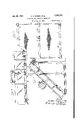
- Figure 1 is a view in elevation showing generally the type of apparatus to which this invention is applied.
- Figure 2 is a longitudinal sectional view of the screen frame.
- Figure 3 is a plan view of the vibrating panel.
- Figure 4 is ,an enlarged detail of the vibrating panel.
- Figure 5 is a plan view of Figure 4.
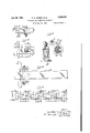
- Figure 6 is an enlarged detail similar to Figure 5 showing a modified construction.
- Figure 7 is a detail section showing the vibrating mechanism
- Figure 8 is a diagram indicating the type of vibration produced by the mechanism of Figure 7.
- the vibrating mechanism is connected so as to transmit the vibratory motion to the screen fabric usually at a single location extending in a line across the middle of the screen cloth.
- the amplitude of vibration of the screen cloth at this point of application and in a line across the screen is a maximum, while at any other point of the screen the amplitudewill be less than this, and will decrease progressively from this maximum point to the points where the screen is pivotally fastened at the ends of the screen cloth assembly. Accordingly, there is only a limited area near the point of application of the vibrating mechanism 7 at which the screen operates with maximum vibratory action.
- means are provided to vibrate an extended area of the screen fabric with this maximum amplitude. This causes the whole of this extended area to operate at maximum screening efficiency and, therefore, greatly increases the output of a given apparatus.
- a screen frame I is supported usually in an inclined position on a suitable base or Suitable adjusting means 3 may be provided for adjusting the angle of inclination of the frame I.
- a screen cloth or fabric 4 is stretched in the frame I and may be tensioned by suitable tensioning devices 5.
- Mounted on a suitable cross frame or bridge 6 is vibrating mechanism indicated generally at 1 from which a connection or stem 8 extends downwardly to be connected to the screen fabric 4 so as to vibrate the latter.
- the stem 8 is connected to the screen fabric through a vibrating panel or sub-frame shown in plan view in Figure 3.
- This panel comprises a plurality of rigid bars or vibrating beams 9, I 0 and II. These are connected together near their ends by coupler bars I2 and I3.
- the middle vibrating bar I0 is connected by means of a yoke I4 to the vibrator stem 8.
- Each of the bars 9, I0 and I I may be secured to the screen fabric, as by fasteners 90, at intervals along their length so as to cause the fabric to move with these bars.
- the end bars 9 and I I are secured to the coupler bars I2 for adjustment lengthwise. This is in order that these bars may move along the coupler bars I2 and Has the screen fabric is tensioned to the desired extent.
- FIG. 4 and 5 In order to accomplish this purpose the structure shown in Figures 4 and 5 may be employed.
- an inwardly extending angle member I5 is secured to each coupler bar I2 and I3 at each end preferably by welding.
- This member I5 forms a clamping block to which the bar 9 or II may be clamped.
- the block I5 has formed therein an elongated slot I6 adapted to receive adjustably therein a clamping bolt II passing through a suitable perforation in the end of the bar II.
- the bars 9, I0 and II may be formed with a channel section so as to render them stiff. Where they engage the coupler bars I2 however,
- the flanges may be cut back as shown at I8 leaving an extended portion of the upper web IQ of the channel to rest upon the bar I2 or I3.
- these extended webs I'9 may slide'upon the bars I2 and I3.
- the bolts I I may be loosened and then the screen fabric tensioned so as to stretch it to the desired extent.
- the bars 9 and Il may move along the bars l2 and I3 so as to accommodate themselves to the stretch of the screen cloth.
- the bolts I! may be tightened to secure the bars 9 and H rigidly to the coupler bars !2 and I3 and to maintain the vibrating panel in adjustment conforming to the tension of the screen cloth.
- the bars 12 and 13 may be provided with inwardly extending angle members 20 and 2
- the members 20 and 2!, as well as the downwardly extending flanges of the bar II, are drilled with aligned holes adapted to receive a guide bar 22 which may be secured in place by nuts 23 at its ends.
- This construction permits the bars 9 and II to slide along the bars l2 and I3 as the screen cloth is tensioned, and at the same time the bars 22 retain the bars 9 and H securely and rigidly assembled with the coupler bars 12 and 13 so as to form a rigid vibrating panel.
- the vibrating mechanism illustrated in Figure 7 may be similar to that described in Patent No. Re. 16,701, issued to Richard A Leahy, and Patent No. 1,712,817, issued to Victor E. Flanagan. As illustrated in Figure 7, it comprises a shaft 24 carrying a cam 25 provided on its periphery with a series of teeth engaging a follower block 26 on a lever 21 pivoted on a pin 28.
- the stem 8 is connected in any suitable manner to be vibrated by the outer end of the lever 21.
- FIG 8 The type of motion imparted by such a cam is illustrated in Figure 8, in which the stroke of the stem 8 is plotted vertically and time horizontally.
- the curve in this figure shows that the downward movement of the stem 8 is gradual as indicated by the portion B of the curve.
- a gradual change of direction is made, indicated by the rounded part of the curve C.
- a rapid upward movement takes place, as indicated by the part D of the curve.
- this portion D of the curve corresponds with the downward movement of the block 26 along the short inclined face of the cam 25.
- the block is suddenly arrested by engaging the succeeding cam surface with a hammer blow. This causes a sharp reversal of the movement of the screen at the point A in Figure 8.
- this reversal point is at the end of the upstroke of the screen fabric and the beginning of the succeeding down stroke. Accordingly, during this upstroke of the cycle of operation the screen cloth rises, projecting the particles of material upward with forces proportional to their masses. A stratification of the materials results, therefore, as the oversize particles seek the top of the material bed, while the undersized particles ride the screen jacket. When the movement of the screen cloth is suddenly arrested at the top of its stroke, the intermediate sized particles, which may become wedged in the meshes of the screen "cloth, are dislodged so that a continuous unblinding action is maintained.
- the material to be screened is passed over the screen fabric while the latter is vibrated and the amplitude of such vibration is maintained substantially uniform throughout the extended area of the screen cloth covered by the vibrating panel shown in Figure 3.
- the material, as it passes over the screen is subjected throughout a major portion of its travel to a vibratory action on the intermediate area of the screen jacket in which not only is the full amplitude of vibration maintained, but the full characteristic of the curve of Figure 8 is maintained.
- a screening apparatus of the character described comprising, a stationary support, an elongated screen fabric, means for mounting said fabric by its ends in said support in a downwardly sloping position and for vibrating movement perpendicular to its plane, said mounting means being constructed to apply endwise tension to said fabric, a framework having longitudinally and laterally extending members and secured to said fabric so as to frame a portion thereof extending laterally to points near its side edges and longitudinally to points intermediate its middle and its ends but substantially spaced from both, and vibrating mechanism connected to vibrate said frame with substantially equal amplitude throughout, whereby to establish on the vibrating fabric successive operating regions including an initial region at the upper end adapted to receive material as fed to the screen and in which ly sloping position and for vibrating movement perpendicular to its plane, said mounting means being constructed to apply endwise tension to said fabric, a frame having longitudinally and lateraIly extending members and secured to said fabric, and means for connecting said members together in relatively shiftable relation so as to permit said members to accommodate themselves to the stretch
Landscapes
- Engineering & Computer Science (AREA)
- Mechanical Engineering (AREA)
- Combined Means For Separation Of Solids (AREA)
Description
July 29, 1941. D. A. WEBER ET AL APPARATUS FOR SCREENING MATERIALS 2 Sheets-Sheet 1 Filed May 15, 1939 July 29, 1941.
D. A. WEBER ET 1.
APPARATUS FOR SCREENING MATERIALS 2 Sheets-Sheet 2 Filed May 15, 1939 81.36 %Dow/2 Patented July 29, 1941 2,250,737 APPARATUS FOR SCREENING MATERIALS Don A. Weber and Spencer A. Stone, Fort Wayne, Ind., assignors to The Deister Concentrator Company, Fort Wayne, Ind., a corporation of Indiana Application May 15, 1939, Serial No. 273,713
2 Claims.
This invention pertains to a screening apparatus of the type in which a screen cloth or fabric is vibrated in a direction normal to the plane of its surface, while the material is caused to travel over the surface of the screen fabric.
One of the objects of this invention is to provide an improved process for screening materials with the aid of this type of apparatus.
Another object is to provide improved screening apparatus which will increase the output thereof.
Another object is to provide screening apparatus in which an extended area of the screen fabric is set into vibration at a substantially uniform amplitude so as to increase the screening efficiency thereof.
Another object is to provide improved means for mounting the screening medium for adjustment of the tension thereof to a correct initial value and arranged to accommodate subsequent readjustment to take up slack accruing during operation without binding or otherwise interfering with the action of said medium in vibration.
Further objects will appear from the following description taken in connection with the accom panying drawings in which Figure 1 is a view in elevation showing generally the type of apparatus to which this invention is applied. Figure 2 is a longitudinal sectional view of the screen frame. Figure 3 is a plan view of the vibrating panel. Figure 4 is ,an enlarged detail of the vibrating panel. Figure 5 is a plan view of Figure 4. Figure 6 is an enlarged detail similar to Figure 5 showing a modified construction. Figure 7 is a detail section showing the vibrating mechanism, and Figure 8 is a diagram indicating the type of vibration produced by the mechanism of Figure 7.
In the ordinary screening apparatus of this type the vibrating mechanism is connected so as to transmit the vibratory motion to the screen fabric usually at a single location extending in a line across the middle of the screen cloth. With this arrangement the amplitude of vibration of the screen cloth at this point of application and in a line across the screen is a maximum, while at any other point of the screen the amplitudewill be less than this, and will decrease progressively from this maximum point to the points where the screen is pivotally fastened at the ends of the screen cloth assembly. Accordingly, there is only a limited area near the point of application of the vibrating mechanism 7 at which the screen operates with maximum vibratory action.
support 2.
In accordance with this invention means are provided to vibrate an extended area of the screen fabric with this maximum amplitude. This causes the whole of this extended area to operate at maximum screening efficiency and, therefore, greatly increases the output of a given apparatus.
In the structure selected for illustration in the drawings, a screen frame I is supported usually in an inclined position on a suitable base or Suitable adjusting means 3 may be provided for adjusting the angle of inclination of the frame I. A screen cloth or fabric 4 is stretched in the frame I and may be tensioned by suitable tensioning devices 5. Mounted on a suitable cross frame or bridge 6 is vibrating mechanism indicated generally at 1 from which a connection or stem 8 extends downwardly to be connected to the screen fabric 4 so as to vibrate the latter.
The stem 8 is connected to the screen fabric through a vibrating panel or sub-frame shown in plan view in Figure 3. This panel comprises a plurality of rigid bars or vibrating beams 9, I 0 and II. These are connected together near their ends by coupler bars I2 and I3. The middle vibrating bar I0 is connected by means of a yoke I4 to the vibrator stem 8. Each of the bars 9, I0 and I I may be secured to the screen fabric, as by fasteners 90, at intervals along their length so as to cause the fabric to move with these bars. The end bars 9 and I I are secured to the coupler bars I2 for adjustment lengthwise. This is in order that these bars may move along the coupler bars I2 and Has the screen fabric is tensioned to the desired extent.
In order to accomplish this purpose the structure shown in Figures 4 and 5 may be employed. In this arrangement an inwardly extending angle member I5 is secured to each coupler bar I2 and I3 at each end preferably by welding. This member I5 forms a clamping block to which the bar 9 or II may be clamped. The block I5 has formed therein an elongated slot I6 adapted to receive adjustably therein a clamping bolt II passing through a suitable perforation in the end of the bar II. The bars 9, I0 and II may be formed with a channel section so as to render them stiff. Where they engage the coupler bars I2 however,
the flanges may be cut back as shown at I8 leaving an extended portion of the upper web IQ of the channel to rest upon the bar I2 or I3. For the end bars 9 and II, these extended webs I'9 may slide'upon the bars I2 and I3. With this arrangement the bolts I I may be loosened and then the screen fabric tensioned so as to stretch it to the desired extent. During such tensioning the bars 9 and Il may move along the bars l2 and I3 so as to accommodate themselves to the stretch of the screen cloth. When the proper tension adjustment has been obtained the bolts I! may be tightened to secure the bars 9 and H rigidly to the coupler bars !2 and I3 and to maintain the vibrating panel in adjustment conforming to the tension of the screen cloth.
In the arrangement of Figure 6, in place of the clamping blocks l5, the bars 12 and 13 may be provided with inwardly extending angle members 20 and 2| spaced. apart so that the downwardly extending flanges of the bars 9 or I I may be positioned therebetween, and their spacing is sufficient to permit movement of the bar H along the bars 12 and 13 to accommodate the tensioning of the screen cloth. The members 20 and 2!, as well as the downwardly extending flanges of the bar II, are drilled with aligned holes adapted to receive a guide bar 22 which may be secured in place by nuts 23 at its ends. This construction permits the bars 9 and II to slide along the bars l2 and I3 as the screen cloth is tensioned, and at the same time the bars 22 retain the bars 9 and H securely and rigidly assembled with the coupler bars 12 and 13 so as to form a rigid vibrating panel.
The vibrating mechanism illustrated in Figure 7 may be similar to that described in Patent No. Re. 16,701, issued to Richard A Leahy, and Patent No. 1,712,817, issued to Victor E. Flanagan. As illustrated in Figure 7, it comprises a shaft 24 carrying a cam 25 provided on its periphery with a series of teeth engaging a follower block 26 on a lever 21 pivoted on a pin 28. The stem 8 is connected in any suitable manner to be vibrated by the outer end of the lever 21.
The type of motion imparted by such a cam is illustrated in Figure 8, in which the stroke of the stem 8 is plotted vertically and time horizontally. The curve in this figure shows that the downward movement of the stem 8 is gradual as indicated by the portion B of the curve. At the bottom of its stroke a gradual change of direction is made, indicated by the rounded part of the curve C. From this point a rapid upward movement takes place, as indicated by the part D of the curve. It will readily be understood that this portion D of the curve corresponds with the downward movement of the block 26 along the short inclined face of the cam 25. At the bottom of this incline the block is suddenly arrested by engaging the succeeding cam surface with a hammer blow. This causes a sharp reversal of the movement of the screen at the point A in Figure 8. It will be noted that this reversal point is at the end of the upstroke of the screen fabric and the beginning of the succeeding down stroke. Accordingly, during this upstroke of the cycle of operation the screen cloth rises, projecting the particles of material upward with forces proportional to their masses. A stratification of the materials results, therefore, as the oversize particles seek the top of the material bed, while the undersized particles ride the screen jacket. When the movement of the screen cloth is suddenly arrested at the top of its stroke, the intermediate sized particles, which may become wedged in the meshes of the screen "cloth, are dislodged so that a continuous unblinding action is maintained.
It will be noted that this action of the screen cloth takes place not only at a single line across the middle of the screen cloth with other points thereof not only falling off in amplitude, but cffecting a progressive smoothing out of the curve of Figure 8, due to resiliency of the screen jacket as the stationary ends thereof are approached, but the full amplitude of vibration and the correct wave form, as indicated in Figure 8, are maintained throughout the area of the screen between the bars 9 and H. Accordingly, a sharp unblinding action and a highly eficient stratifying action are maintained throughout the area of the vibrating panel. As this area is several times the effective area of a screen having only a single vibrating bar, it will be clear that a very considerable improvement in efficiency is attained.
It will be noted, therefore, that in accordance with the process of this invention, the material to be screened is passed over the screen fabric while the latter is vibrated and the amplitude of such vibration is maintained substantially uniform throughout the extended area of the screen cloth covered by the vibrating panel shown in Figure 3. By this process the material, as it passes over the screen, is subjected throughout a major portion of its travel to a vibratory action on the intermediate area of the screen jacket in which not only is the full amplitude of vibration maintained, but the full characteristic of the curve of Figure 8 is maintained. In other words, throughout this portion of its travel the material is treated with a rapid upward movement, which is suddenly arrested so as to maintain a strong unblinding action, followed by a much more gradual downward movement, permitting the particles to settle on the screen, and a relatively gradual change from downward to upward movement so as to avoid wedging intermediate sized particles in the meshes of the screen.
While this invention has been described as embodied in a unitary apparatus, it will be understood that certain individual features or subcombinations thereof may be useful by themselves without reference to other features or the main combination, and that the employment of such individual features or subcombinations is contemplated by this invention as within the scope of the appended claims.
It is obvious furthermore that various changes may be made in the details of construction or procedure within the scope of the appended claims without departing from the spirit of this invention, and that accordingly the invention is not limited to the specific details shown or described.
Having thus described the invention what is claimed is:
1. A screening apparatus of the character described, comprising, a stationary support, an elongated screen fabric, means for mounting said fabric by its ends in said support in a downwardly sloping position and for vibrating movement perpendicular to its plane, said mounting means being constructed to apply endwise tension to said fabric, a framework having longitudinally and laterally extending members and secured to said fabric so as to frame a portion thereof extending laterally to points near its side edges and longitudinally to points intermediate its middle and its ends but substantially spaced from both, and vibrating mechanism connected to vibrate said frame with substantially equal amplitude throughout, whereby to establish on the vibrating fabric successive operating regions including an initial region at the upper end adapted to receive material as fed to the screen and in which ly sloping position and for vibrating movement perpendicular to its plane, said mounting means being constructed to apply endwise tension to said fabric, a frame having longitudinally and lateraIly extending members and secured to said fabric, and means for connecting said members together in relatively shiftable relation so as to permit said members to accommodate themselves to the stretch of said fabric when the latter is 10 tensioned.
DON A. WEBER. SPENCER A. STONE.
Priority Applications (1)
| Application Number | Priority Date | Filing Date | Title |
|---|---|---|---|
| US273713A US2250737A (en) | 1939-05-15 | 1939-05-15 | Apparatus for screening materials |
Applications Claiming Priority (1)
| Application Number | Priority Date | Filing Date | Title |
|---|---|---|---|
| US273713A US2250737A (en) | 1939-05-15 | 1939-05-15 | Apparatus for screening materials |
Publications (1)
| Publication Number | Publication Date |
|---|---|
| US2250737A true US2250737A (en) | 1941-07-29 |
Family
ID=23045083
Family Applications (1)
| Application Number | Title | Priority Date | Filing Date |
|---|---|---|---|
| US273713A Expired - Lifetime US2250737A (en) | 1939-05-15 | 1939-05-15 | Apparatus for screening materials |
Country Status (1)
| Country | Link |
|---|---|
| US (1) | US2250737A (en) |
Cited By (1)
| Publication number | Priority date | Publication date | Assignee | Title |
|---|---|---|---|---|
| US3121679A (en) * | 1958-05-27 | 1964-02-18 | Novo Ind Corp | Method of operating screens |
-
1939
- 1939-05-15 US US273713A patent/US2250737A/en not_active Expired - Lifetime
Cited By (1)
| Publication number | Priority date | Publication date | Assignee | Title |
|---|---|---|---|---|
| US3121679A (en) * | 1958-05-27 | 1964-02-18 | Novo Ind Corp | Method of operating screens |
Similar Documents
| Publication | Publication Date | Title |
|---|---|---|
| US1997740A (en) | Plural cloth screening apparatus | |
| GB1106513A (en) | Sieve machines | |
| US4361240A (en) | Material separating machine | |
| US2880871A (en) | Process and device for sifting solid and liquid materials | |
| DE1196946B (en) | Sieving machine | |
| US3706376A (en) | Screen with differently tensioned surface zones | |
| RU2241550C1 (en) | Vibratory screen | |
| US2250737A (en) | Apparatus for screening materials | |
| US2777579A (en) | Screen cloth supporting frame for a vibrating screen | |
| US1983676A (en) | Method of and apparatus for screening | |
| US3225926A (en) | Vibrating sieves | |
| US3616905A (en) | Arrangement for classifying of liquid suspensions and of solid materials | |
| US2308572A (en) | Rod screen | |
| US1864940A (en) | Apparatus for screening materials | |
| GB455628A (en) | Vibratory screen and method of screening | |
| DE2016199C3 (en) | Sieving machine | |
| US2137753A (en) | Vibratory screening device | |
| US1906336A (en) | Screening apparatus | |
| US2118782A (en) | Screen | |
| GB2073618A (en) | Vibratory screening panels | |
| US3315804A (en) | Apparatus for riffle screen sizing | |
| US1431987A (en) | Separator screen | |
| SU1579584A1 (en) | Screen grate | |
| US1332685A (en) | Method of and apparatus for screening materials | |
| US1565883A (en) | Screen |