US2248564A - Marine electric gear shift - Google Patents
Marine electric gear shift Download PDFInfo
- Publication number
- US2248564A US2248564A US249176A US24917639A US2248564A US 2248564 A US2248564 A US 2248564A US 249176 A US249176 A US 249176A US 24917639 A US24917639 A US 24917639A US 2248564 A US2248564 A US 2248564A
- Authority
- US
- United States
- Prior art keywords
- gear shift
- motor
- crank
- shift lever
- contact
- Prior art date
- Legal status (The legal status is an assumption and is not a legal conclusion. Google has not performed a legal analysis and makes no representation as to the accuracy of the status listed.)
- Expired - Lifetime
Links
Images
Classifications
-
- G—PHYSICS
- G05—CONTROLLING; REGULATING
- G05B—CONTROL OR REGULATING SYSTEMS IN GENERAL; FUNCTIONAL ELEMENTS OF SUCH SYSTEMS; MONITORING OR TESTING ARRANGEMENTS FOR SUCH SYSTEMS OR ELEMENTS
- G05B19/00—Program-control systems
- G05B19/02—Program-control systems electric
- G05B19/04—Program control other than numerical control, i.e. in sequence controllers or logic controllers
- G05B19/06—Program control other than numerical control, i.e. in sequence controllers or logic controllers using cams, discs, rods, drums or the like
-
- F—MECHANICAL ENGINEERING; LIGHTING; HEATING; WEAPONS; BLASTING
- F16—ENGINEERING ELEMENTS AND UNITS; GENERAL MEASURES FOR PRODUCING AND MAINTAINING EFFECTIVE FUNCTIONING OF MACHINES OR INSTALLATIONS; THERMAL INSULATION IN GENERAL
- F16H—GEARING
- F16H61/00—Control functions within control units of change-speed- or reversing-gearings for conveying rotary motion ; Control of exclusively fluid gearing, friction gearing, gearings with endless flexible members or other particular types of gearing
- F16H61/02—Control functions within control units of change-speed- or reversing-gearings for conveying rotary motion ; Control of exclusively fluid gearing, friction gearing, gearings with endless flexible members or other particular types of gearing characterised by the signals used
- F16H61/0202—Control functions within control units of change-speed- or reversing-gearings for conveying rotary motion ; Control of exclusively fluid gearing, friction gearing, gearings with endless flexible members or other particular types of gearing characterised by the signals used the signals being electric
-
- G—PHYSICS
- G05—CONTROLLING; REGULATING
- G05B—CONTROL OR REGULATING SYSTEMS IN GENERAL; FUNCTIONAL ELEMENTS OF SUCH SYSTEMS; MONITORING OR TESTING ARRANGEMENTS FOR SUCH SYSTEMS OR ELEMENTS
- G05B2219/00—Program-control systems
- G05B2219/30—Nc systems
- G05B2219/49—Nc machine tool, till multiple
- G05B2219/49269—Single motor for different drives, switch, change gears
-
- Y—GENERAL TAGGING OF NEW TECHNOLOGICAL DEVELOPMENTS; GENERAL TAGGING OF CROSS-SECTIONAL TECHNOLOGIES SPANNING OVER SEVERAL SECTIONS OF THE IPC; TECHNICAL SUBJECTS COVERED BY FORMER USPC CROSS-REFERENCE ART COLLECTIONS [XRACs] AND DIGESTS
- Y10—TECHNICAL SUBJECTS COVERED BY FORMER USPC
- Y10S—TECHNICAL SUBJECTS COVERED BY FORMER USPC CROSS-REFERENCE ART COLLECTIONS [XRACs] AND DIGESTS
- Y10S74/00—Machine element or mechanism
- Y10S74/08—Marine control-ship transmission control means
-
- Y—GENERAL TAGGING OF NEW TECHNOLOGICAL DEVELOPMENTS; GENERAL TAGGING OF CROSS-SECTIONAL TECHNOLOGIES SPANNING OVER SEVERAL SECTIONS OF THE IPC; TECHNICAL SUBJECTS COVERED BY FORMER USPC CROSS-REFERENCE ART COLLECTIONS [XRACs] AND DIGESTS
- Y10—TECHNICAL SUBJECTS COVERED BY FORMER USPC
- Y10T—TECHNICAL SUBJECTS COVERED BY FORMER US CLASSIFICATION
- Y10T74/00—Machine element or mechanism
- Y10T74/19—Gearing
- Y10T74/19219—Interchangeably locked
- Y10T74/19372—Single forward and reverse speeds
-
- Y—GENERAL TAGGING OF NEW TECHNOLOGICAL DEVELOPMENTS; GENERAL TAGGING OF CROSS-SECTIONAL TECHNOLOGIES SPANNING OVER SEVERAL SECTIONS OF THE IPC; TECHNICAL SUBJECTS COVERED BY FORMER USPC CROSS-REFERENCE ART COLLECTIONS [XRACs] AND DIGESTS
- Y10—TECHNICAL SUBJECTS COVERED BY FORMER USPC
- Y10T—TECHNICAL SUBJECTS COVERED BY FORMER US CLASSIFICATION
- Y10T74/00—Machine element or mechanism
- Y10T74/19—Gearing
- Y10T74/19219—Interchangeably locked
- Y10T74/19377—Slidable keys or clutches
- Y10T74/19414—Single clutch shaft
- Y10T74/19419—Progressive
- Y10T74/19423—Multiple key
- Y10T74/19428—Spur
- Y10T74/19437—Electrically operated
-
- Y—GENERAL TAGGING OF NEW TECHNOLOGICAL DEVELOPMENTS; GENERAL TAGGING OF CROSS-SECTIONAL TECHNOLOGIES SPANNING OVER SEVERAL SECTIONS OF THE IPC; TECHNICAL SUBJECTS COVERED BY FORMER USPC CROSS-REFERENCE ART COLLECTIONS [XRACs] AND DIGESTS
- Y10—TECHNICAL SUBJECTS COVERED BY FORMER USPC
- Y10T—TECHNICAL SUBJECTS COVERED BY FORMER US CLASSIFICATION
- Y10T74/00—Machine element or mechanism
- Y10T74/19—Gearing
- Y10T74/19219—Interchangeably locked
- Y10T74/19377—Slidable keys or clutches
- Y10T74/19414—Single clutch shaft
- Y10T74/19484—Single speed forward and reverse
-
- Y—GENERAL TAGGING OF NEW TECHNOLOGICAL DEVELOPMENTS; GENERAL TAGGING OF CROSS-SECTIONAL TECHNOLOGIES SPANNING OVER SEVERAL SECTIONS OF THE IPC; TECHNICAL SUBJECTS COVERED BY FORMER USPC CROSS-REFERENCE ART COLLECTIONS [XRACs] AND DIGESTS
- Y10—TECHNICAL SUBJECTS COVERED BY FORMER USPC
- Y10T—TECHNICAL SUBJECTS COVERED BY FORMER US CLASSIFICATION
- Y10T74/00—Machine element or mechanism
- Y10T74/20—Control lever and linkage systems
- Y10T74/20012—Multiple controlled elements
- Y10T74/20018—Transmission control
- Y10T74/2003—Electrical actuator
Definitions
- This invention relates to remote control gear shift mechanisms, and more particularly, though not exclusively, to an electric motor driven control for shifting the gears of a marine engine.
- the objects of my invention may be thus briefly summarized, viz., to provide a remote control for a marine gear shift which will be automatically responsive to the closing of one switch, or a plurality of switches, selectively located in any desired part of the boat or ship; to provide a power operated gear shift mechanism which will positively engage the gears and then release the throw-in pressure to such an extent that, though the gears. are held firmly in mesh,
- Fig. 2 is an enlarged view, fragmental, showing the gear shift lever and its motor drive mechanism in various operating positions;
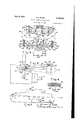
- Fig. 3 is aWiring diagram showing the han controlledswitches, the relays and the cam 0perated switches for the motor control circuits;
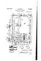
- Fig. 4 is a plan view of the gear shift mechanism with the top of its cabinet broken away;
- Fig. 5 is a detail sectional view taken on the line V--V of Fig. 4.
- I have shown a conventional type of small motor-driven, pleasure boat Ill having an engine I2 with a gear shift rod 13 controlled by the usual gear shift lever M.
- the gear shift rod controls any suitable transmission mechanism, not shown, by which a forward or reverse motion or neutral position can be established for the driving connection between the motor and the propeller shaft l5.
- the boat is equipped with dual steering Wheels l6 and I1, arranged as may be desired in different parts of the boat. All the parts above described can be widely. varied in their detail structure, as they form no particular part of my present invention.
- a base I8 In juxtaposition to the transmission mechanism I securely mount in the boat a base I8, upon which my improved gear shift mechanism is mounted.
- This mechanism com-prises a series wound, reversible electric motor 20, which can be of relatively small capacity, approximating that employed as a starter motor on automobiles.
- This motor is suitably bolted to the base l8 and its drive shaft 2
- I mount on the shaft 2
- the several bearings 2-2, 23 and 21 are of the thrust-bearing type in order to take up the end thrust from the worm gear transmission.
- the shaft 26 projects at one end through the metallic cabinet wall 28, which is flanged at its base and preferably made fast with a water-tight joint to the base l8 and provided along its top with spot welded nuts 29, for the attachment thereto of a suitable cover 3%, which may also be designed and adapted to afford a water-proof closure for the top of the cabinet.
- serve, by engagement with nuts 29, to secure the cover in position on the cabinet.
- one end of shaft projects without this cabinet and passes through a suitable packing gland 32 which will seal against the ingress of water at that point.
- a crank 33 having a groove 34 surrounding its cylindrical end and a demountable connection 35 is adapted to be slipped endwise on and oh of this crank, the connection carrying a radial bore 35 closed with a plug 31 between which and a ball 38 is interposed a spring 39.
- connection 35 carries a threaded shank which is screwed into a turn buckle sleeve 4
- the latter attachment 35 is demountably engaged with a grooved pin43 which, a shown in Fig. 2, is screwed into the gear shift lever I4 at the desired point of attachment.
- this pin 43 may, as shown in Fig. 6, be adjustable on the gear shift lever by mounting it on'one member 44 of a clamp which, when bolted to the cooperative clamp member 45, will engage the handle and hold the pin at any-desired position of adjustment lengthwise of the handle, according to the leverage required and the length of throw necessary for the change of gears.
- cams all substantially alike and numbered 46, 41, '48 and 49, and these ca-ms have collars carrying set screws by means of which they may be set in the desired relative adjustment upon shaft'25;
- Each cam controls its respective-spring 'c'ontactmember 46a, 41a, 48a, and 49a, (Fig. 3) and act to force said contacts outwardly into A con-nec- 60, and thence by lead 6! branching to the relays 62 and 63.
- the contact members 411) and 48b are cross connected to the lead 80, which in'turn'branch'es and is connected to the middle contact with which each of the two hand switches 5! and 52 respectively coacts.
- the contact 4% is connected by the lead 53 and its branches to corresponding contacts controlled by switches 5
- the contact 4% is connected by the lead 54 and its branches to corresponding contacts for the switches 51 and 52.
- Each of. these switches is provided with a stop indicator 55 for the non-operative position of the switch, eachswitch having a ground lead 56.
- a movable contact 68 and a stationary contact 69 and a second movable contact 10 Associated with the relay 52 is a movable contact 68 and a stationary contact 69 and a second movable contact 10, it being contemplated, when this relay solenoid is energized, that 68 will contact -64 and 70 will contact 69.
- the relay 63 controls similar contact members 83a; 69a, and 10a, which will be caused to make similar contact when '63 is energized.
- a heavy power line H connects :68 and Me by a lead 12 into one end of the held in the motor 20.
- a heavy power line 13 connects the contacts 69 and 68a with a lead connected to the other end of the field of said motor 20.
- the contacts 10 and We are connected in multiple by the heavy power cable to the armature of the motor, which in turn is grounded by the wire 16 to complete the circuit to the battery through its ground wire 11.
- cam 48 will have run out from under its contact and opened the circuit of relay 63, killing the motor circuit, and the contacts controlled by cam 41 will be open.
- the relay 63 will be energized in the manner already described, and current will'pass in the same direction as last described through the motor, causing crank arm 33 to be turned clockwise and shift the gear shift lever to the position indicated by the dotted circle C at the right, Fig. 2, at which time contact 49a will have run off cam l9 and the circuit to relay 63 will be broken.
- cam 41 As cam 49 moves cam 41 will close its circuits, in just the same way as cam 48 closed its circuits when cam 46 moved, and thus the circuit is set so that on the return of the control switch from either running contact to the neutral contact, the motor will travel reversely to its last direction of travel and restore the crank to the neutral position shown in Fig. 2, and then will break the circuit as cam 47 or 48 runs out from under its respective contact and opens its relay control circuits.
- crank 33 approaches and assumes dead center position on either side as it moves the gear shift lever to its full forward or reverse gear engaging position, and inasmuch as considerable power is required often to accomplish the requisite positive engagement of the gears, it will be apparent that even a small motor may accomplish this by reason of the great multiplication of its power tained on either side at the point of disappearance of the angle between the crank and the connecting rod, and, therefore, with a small motor I can supply all needed power to shift even gears which are very hard to manipulate. It will be further noted that the counter-clockwise movement of the crank to the lower dotted circular position at the left, Fig.
- , by changing the screw setting of either connection 40 to the sleeve ll, and by shifting the clamp 44 up or down on the gear shift lever, are such as jointly to provide for any requisite angular throw for the gear shift lever and afford much flexibility and refinement in the several adjustments provided for this purpose.
- Another means for control of the throw of the gear shift lever is the adjustment of the cams which can be so positioned with respect to each other on shaft 26 as to control the angle of throw of the, gear shift lever. It will be noted from Fig. 3 thatthe extent of the cam to the left of the contact point 46w makes provision for this adjustment, and by turning the cam 46 angularly to the right an increased extent of cam surface will bedisposed inposition tocontrol the contact 46a. and thuswill hold it'closed longer, and,
- the whole mechanism is compact, water,- proof, comparatively inexpensive, and readily accessible for inspection and repair. But light wiring is required, tobe run over the boat, and the power cables are short leadsv with only those exposed that lead to the battery and to the ground, which greatly simplifies wiring cost and danger to the boat.
- a reversible electric motor for operating the gear shift lever of a marine transmission
- a crank driven by said motor means connecting the crank to said shift lever
- a manually operable electric switch electric circuits controlled by said switch for forward, reverse and neutral positions of said transmissions
- relays for said electric circuits controlled by said switch power circuits for said motor controlled by the relays for selectively throwing the shift lever into any of the said positions, and make and break switches in circuit with said manually operable switch controlled by the position of the motor driven crank and adapted to stop the motor automatically when the shift lever reaches its selected forward, reverse or neutral position.
- a lever for shifting the transmission gears an electric motor driven mechanism for shifting said lever comprising a cabinet containing a high speed reversible motor, a worm reduction gearing driven by said motor, a crank driven by said gearing, a driving connection from the crank to said lever disposed to assume dead center positions as the lever approaches positions for engaging the gears for forward and reverse driving, electrical circuit connection controlled by the crank and adapted automatically to limit the angular travel of said crank, and. remote manual switch means to control selectively the direction of movement of the motor to shift the gears.
- a gear shift mechanism in which the automatic switch control of circuits operated by the crank is adapted to move said driving connection beyond dead center position when shifting the gears to position for forward driving, thereby to relieve undue pressure on the transmission after the gears have been fully engaged.
- a shifter element for shifting the gear shift lever of a marine transmission into its forward, reverse and neutral positions selectively, a shifter element, a reversible electric motorfor actuating said element, a crank shaft connected to the shifter element, a worm gear speed reduction drive operatively connecting the motor to the crank shaft, control means for the motor comprising a manually operable switch for selecting said forward, reverse and neutral positions of said shift lever, low amperage circuits controlled by said manually operable switch, limit switches in said circuits operable by said crank shaft, relays in said circuits, and power circuits for the motor controlled by the relays, said relays being controlled jointly by the manually operable switch and the limit switches and adapted automatioally to stop the motor by interrupting the power circuits when the shift lever reaches the 10 selected position indicated by said manually operable switch.
- a shifter 15 element a reversible electric motor for actuating said element, a crank shaft connected to the shifter element, a worm gear speed reduction drive operatively connecting the motor to the crank shaft, control means for the motor comprising a manually operable switch for selecting said forward, reverse and neutral positions of said'shift lever, 10w amperage circuits controlled by said manually operable switch, limit switches in said circuits operable by said crank shaft, relays in said circuits, and adjustable means interposed between the crank shaft and the shift lever to vary the extent of motion imparted to said lever by the motor.
Landscapes
- Engineering & Computer Science (AREA)
- General Engineering & Computer Science (AREA)
- Mechanical Engineering (AREA)
- Physics & Mathematics (AREA)
- General Physics & Mathematics (AREA)
- Automation & Control Theory (AREA)
- Gear-Shifting Mechanisms (AREA)
Description
July 8, 1941. D. E. WOOD MARINE ELECTRIC GEAR SHIFT 2 Sheets-Sheet 1 .Filed Jan. 3 1939 INVENTOR DEL/WONT %z J ATTORNEY! July 8,1941. D. E. WOOD 2,248,564
MARINE ELEQTRIC GEAR SHIFT Filed 'Jan. 3, 1939 I 2 Sheets-Sheet 2 2? F1 .4 I I. 2 a 1 0 fr w INVENTOR ATTORNEYS Patented July 8, 1941 TENT OFFICE 6 Claims.
This invention relates to remote control gear shift mechanisms, and more particularly, though not exclusively, to an electric motor driven control for shifting the gears of a marine engine.
The objects of my invention may be thus briefly summarized, viz., to provide a remote control for a marine gear shift which will be automatically responsive to the closing of one switch, or a plurality of switches, selectively located in any desired part of the boat or ship; to provide a power operated gear shift mechanism which will positively engage the gears and then release the throw-in pressure to such an extent that, though the gears. are held firmly in mesh,
the holding pressure is not enough to cause excessive wear on the transmission parts; ,to provide an electrical gear shift mechanism in which the number and. speed of the moving parts is reduced to a minimum, and in which electromagnetic relay means, cooperating with cams on a driven shaft, cause the mechanism to move accurately to a predetermined selective gear-engaging position; to provide an electrically controlled and operated gear shift mechanism in which the arrangement and construction of the parts requires a minimum amount of expensive, heavy duty electric cable, and in which the remote, light duty, control circuits carry only sufficient current to energize the relays that control the main power circuits; to provide an electrically driven gear shift which can be driven by a small motor but which will, due to the means employed to transmit itsv motion to the gearshift lever, produce a great amount of power at the point in the throw, when most power is needed to efiect a shifting of the gears; to provide a gear shift which is capable of being connected to the transmission without removing the manually operable shift lever, so that in case of failure of the power supply, the gears may still be shifted, as usual, by hand; to provide a gear shift which is readily adjustable to, and therefore adapted for use with, various transmissions that require a different angular throw of the shift lever to effect a change of the gears; and to provide a gear shift mechanism having all of the above mentioned features which will be capable of adaptation to practically any type of boat or ship without having to make material changes in the installation of the engine or transmission. 7 V V 7 Other objects and advantages will more fully appear by reference to the illustrated embodiment of my invention shown in the accompanying drawings, in which- Fig. 1 is a side elevational view of a boat equipped with my improved remote control gear shift mechanism;
Fig. 2 is an enlarged view, fragmental, showing the gear shift lever and its motor drive mechanism in various operating positions; I
Fig. 3 is aWiring diagram showing the han controlledswitches, the relays and the cam 0perated switches for the motor control circuits;
Fig. 4 is a plan view of the gear shift mechanism with the top of its cabinet broken away;
Fig. 5 is a detail sectional view taken on the line V--V of Fig. 4; and
.Fig. 5.
Similar reference numerals refer to similar parts throughout the drawings.
In the embodiment of my invention illustrated, I have shown a conventional type of small motor-driven, pleasure boat Ill having an engine I2 with a gear shift rod 13 controlled by the usual gear shift lever M. The gear shift rod controls any suitable transmission mechanism, not shown, by which a forward or reverse motion or neutral position can be established for the driving connection between the motor and the propeller shaft l5. The boat is equipped with dual steering Wheels l6 and I1, arranged as may be desired in different parts of the boat. All the parts above described can be widely. varied in their detail structure, as they form no particular part of my present invention.
In juxtaposition to the transmission mechanism I securely mount in the boat a base I8, upon which my improved gear shift mechanism is mounted. This mechanism com-prises a series wound, reversible electric motor 20, which can be of relatively small capacity, approximating that employed as a starter motor on automobiles. This motor is suitably bolted to the base l8 and its drive shaft 2| is journalled in bearings 22 and 23 also mounted on, or cast integral with, the base. I mount on the shaft 2| between said bearings a worm 24 which meshes with a Worm gear 25 fast on a cross shaft 26, journalled at its ends in the bearings 21, also attached to, or formed integral with, the base IS. The several bearings 2-2, 23 and 21 are of the thrust-bearing type in order to take up the end thrust from the worm gear transmission. The shaft 26 projects at one end through the metallic cabinet wall 28, which is flanged at its base and preferably made fast with a water-tight joint to the base l8 and provided along its top with spot welded nuts 29, for the attachment thereto of a suitable cover 3%, which may also be designed and adapted to afford a water-proof closure for the top of the cabinet. Bolts carrying wing nuts 3| serve, by engagement with nuts 29, to secure the cover in position on the cabinet.
It will be noted that one end of shaft projects without this cabinet and passes through a suitable packing gland 32 which will seal against the ingress of water at that point. On the end of this shaft is provided, integrally or otherwise, a crank 33 having a groove 34 surrounding its cylindrical end and a demountable connection 35 is adapted to be slipped endwise on and oh of this crank, the connection carrying a radial bore 35 closed with a plug 31 between which and a ball 38 is interposed a spring 39. The ball 38 engages a slightly contracted seat at the inner end of the bore sothat it will not escape, though approximately half of the ball will project into the bore of the connection 35 and lay-engagement in groove 34 will form a spring latch holding the member 35 normally-engaged with, and yet readily detachable from the crank 33. The connection 35 carries a threaded shank which is screwed into a turn buckle sleeve 4| and held in adjusted position by a jam nut 42. 'tion 35, similar to that already described except that its shank 40 is reversely threaded, is screwed into the other end of the turn buckle sleeve M and held set in adjustment by its jam nut 42. The latter attachment 35 is demountably engaged with a grooved pin43 which, a shown in Fig. 2, is screwed into the gear shift lever I4 at the desired point of attachment. If desired, however, this pin 43 may, as shown in Fig. 6, be adjustable on the gear shift lever by mounting it on'one member 44 of a clamp which, when bolted to the cooperative clamp member 45, will engage the handle and hold the pin at any-desired position of adjustment lengthwise of the handle, according to the leverage required and the length of throw necessary for the change of gears.
I mount on the shaft 26 within the cabinet four cams all substantially alike and numbered 46, 41, '48 and 49, and these ca-ms have collars carrying set screws by means of which they may be set in the desired relative adjustment upon shaft'25; Each cam controls its respective-spring 'c'ontactmember 46a, 41a, 48a, and 49a, (Fig. 3) and act to force said contacts outwardly into A con-nec- 60, and thence by lead 6! branching to the relays 62 and 63.
Referring now to Fig. 3, it will be seen that the main power circuit 5| leads to a contact engagement with the stationary contacts 4619,
41b, 48b, and 49b respectively. The contact members 411) and 48b are cross connected to the lead 80, which in'turn'branch'es and is connected to the middle contact with which each of the two hand switches 5! and 52 respectively coacts. The contact 4% is connected by the lead 53 and its branches to corresponding contacts controlled by switches 5| and 52. The contact 4% is connected by the lead 54 and its branches to corresponding contacts for the switches 51 and 52. Each of. these switches is provided with a stop indicator 55 for the non-operative position of the switch, eachswitch having a ground lead 56.
These several leads are brought out through the walls of the cabinet through suitable insulators preferably water-'tight,-and the several conpoint 64 for the relay 62, and 55 for the relay 63, a branch circuit 56 being taken off lead 5| adjacent to relay 82 to supply current for that relay and this circuit being extended and connected in multiple to the movable contact member 46a and 4111. In like manner a similar circuit Bl is derived from circuit 6| for the relay 63 and is connected in multiple to the movable contacts 48a and 49a.
Associated with the relay 52 is a movable contact 68 and a stationary contact 69 and a second movable contact 10, it being contemplated, when this relay solenoid is energized, that 68 will contact -64 and 70 will contact 69. In like manner, the relay 63 controls similar contact members 83a; 69a, and 10a, which will be caused to make similar contact when '63 is energized. A heavy power line H connects :68 and Me by a lead 12 into one end of the held in the motor 20. A heavy power line 13 connects the contacts 69 and 68a with a lead connected to the other end of the field of said motor 20. The contacts 10 and We are connected in multiple by the heavy power cable to the armature of the motor, which in turn is grounded by the wire 16 to complete the circuit to the battery through its ground wire 11.
In operation, when the transmission and gear shift lever are in neutral position shown in Fig. 2, the cams will stand in the positions indicated in Figs. 13 and a. Upon moving either switch 5| or 52 from its inoperative position 55 on to the contact for :lead 53, relay :62 will be energized through 53, 46a, 66, iii, 59, battery 58, to the :ground, closing contacts 68 to 4 and 10 to 59. Thereupon, current will flow from battery over 61,54, 68, H and 12 through the field-0f the motor, returning through M, 13, 69, 10 and 15 to the motor armature and thence by 16 to the ground, and by lead 11 'ito the battery. This will drive the motor in a direction which will turn its crank 33 counter-clockwise, as viewed in Fig. 2, and in doing so it will rock the crank connections into dead center position in which the lever 44 is shifted to its extreme gear engaging position indicated :by the dotted circle A for the forward drive, after which the crank arm continues to turn to .a position beyond dead center far enough to retract the gear shift mm M sufficiently to switch 51 or filgwhichever is controlling the boat, on to the middle or neutral contact, current will flow from battery through 61 :67, 18a, 18b, and back to the ground, energizing relay 3 and closing contacts 55-580; and Film-10a, whereupon the motor circuits are established as follows: from 61 through 14 in reverse direction through the fields and out through 12,-69a, 10a and 15 to the armature and by lead 16 to the ground, whereupon the motor will turn in the reverse direction to restore the 'crank arm 33 to the neutral position shown lnEig. 2', at which time cam 48 will have run out from under its contact and opened the circuit of relay 63, killing the motor circuit, and the contacts controlled by cam 41 will be open. When the control switch is thrown to the right hand contact,.the relay 63 will be energized in the manner already described, and current will'pass in the same direction as last described through the motor, causing crank arm 33 to be turned clockwise and shift the gear shift lever to the position indicated by the dotted circle C at the right, Fig. 2, at which time contact 49a will have run off cam l9 and the circuit to relay 63 will be broken.
As cam 49 moves cam 41 will close its circuits, in just the same way as cam 48 closed its circuits when cam 46 moved, and thus the circuit is set so that on the return of the control switch from either running contact to the neutral contact, the motor will travel reversely to its last direction of travel and restore the crank to the neutral position shown in Fig. 2, and then will break the circuit as cam 47 or 48 runs out from under its respective contact and opens its relay control circuits.
It is important to note that the crank 33 approaches and assumes dead center position on either side as it moves the gear shift lever to its full forward or reverse gear engaging position, and inasmuch as considerable power is required often to accomplish the requisite positive engagement of the gears, it will be apparent that even a small motor may accomplish this by reason of the great multiplication of its power tained on either side at the point of disappearance of the angle between the crank and the connecting rod, and, therefore, with a small motor I can supply all needed power to shift even gears which are very hard to manipulate. It will be further noted that the counter-clockwise movement of the crank to the lower dotted circular position at the left, Fig. 2, for forward driving will have eased the gear shift lever back from its extreme gear engaging position A to B, this being important to relieve the heavy thrust, required to engage the gears, during their normal driving relationship. Thus I do mechanically what now is done by hand when the operator eases the gear shift lever back out after throwing it into forward driving position. This same action could be obtained for the reverse drive if it be desired, but since the gears are not held long in mesh driving in reverse, it is not so important for this particular purpose. If, by carelessness, both switches and 52 are left on different contacts, a manipulation of either may cause the battery to be short circuited, blowing the fuse 60. If this occurs the connecting arm of the crank drive can be readily disengaged from the motor crank by pulling connections 35 from the gear shift lever and crank, so that the lever is freed and the gears can be shifted by hand, as usual.
The adjustments provided by turning the turn buckle sleeve 4|, by changing the screw setting of either connection 40 to the sleeve ll, and by shifting the clamp 44 up or down on the gear shift lever, are such as jointly to provide for any requisite angular throw for the gear shift lever and afford much flexibility and refinement in the several adjustments provided for this purpose.
Another means for control of the throw of the gear shift lever is the adjustment of the cams which can be so positioned with respect to each other on shaft 26 as to control the angle of throw of the, gear shift lever. It will be noted from Fig. 3 thatthe extent of the cam to the left of the contact point 46w makes provision for this adjustment, and by turning the cam 46 angularly to the right an increased extent of cam surface will bedisposed inposition tocontrol the contact 46a. and thuswill hold it'closed longer, and,
therefore, obtain a greater pull out or retraction of the gear shift leverjfrom its extreme position to, the left, Fig.2; I
The whole mechanism is compact, water,- proof, comparatively inexpensive, and readily accessible for inspection and repair. But light wiring is required, tobe run over the boat, and the power cables are short leadsv with only those exposed that lead to the battery and to the ground, which greatly simplifies wiring cost and danger to the boat.
What I claim is:
1. In a motor driven attachment for operating the gear shift lever of a marine transmission, a reversible electric motor, a crank driven by said motor, means connecting the crank to said shift lever, a manually operable electric switch, electric circuits controlled by said switch for forward, reverse and neutral positions of said transmissions, relays for said electric circuits controlled by said switch, power circuits for said motor controlled by the relays for selectively throwing the shift lever into any of the said positions, and make and break switches in circuit with said manually operable switch controlled by the position of the motor driven crank and adapted to stop the motor automatically when the shift lever reaches its selected forward, reverse or neutral position.
2. In a remote control for a marine transmission, a lever for shifting the transmission gears, an electric motor driven mechanism for shifting said lever comprising a cabinet containing a high speed reversible motor, a worm reduction gearing driven by said motor, a crank driven by said gearing, a driving connection from the crank to said lever disposed to assume dead center positions as the lever approaches positions for engaging the gears for forward and reverse driving, electrical circuit connection controlled by the crank and adapted automatically to limit the angular travel of said crank, and. remote manual switch means to control selectively the direction of movement of the motor to shift the gears.
3. A gear shift mechanism according to claim 2, in which the automatic switch control of circuits operated by the crank is adapted to move said driving connection beyond dead center position when shifting the gears to position for forward driving, thereby to relieve undue pressure on the transmission after the gears have been fully engaged.
4. In an actuating mechanism for the gear shift lever of a marine transmission according to claim 2 the provision of means to vary the length and point of attachment of the driving connection between the crank and gear shift lever to adapt the actuating mechanism for use as an attachment to different transmissions.
5. In a mechanism for shifting the gear shift lever of a marine transmission into its forward, reverse and neutral positions selectively, a shifter element, a reversible electric motorfor actuating said element, a crank shaft connected to the shifter element, a worm gear speed reduction drive operatively connecting the motor to the crank shaft, control means for the motor comprising a manually operable switch for selecting said forward, reverse and neutral positions of said shift lever, low amperage circuits controlled by said manually operable switch, limit switches in said circuits operable by said crank shaft, relays in said circuits, and power circuits for the motor controlled by the relays, said relays being controlled jointly by the manually operable switch and the limit switches and adapted automatioally to stop the motor by interrupting the power circuits when the shift lever reaches the 10 selected position indicated by said manually operable switch.
6. In a mechanism for shifting the gear shift lever of a marine transmission into its forward,
reverse and neutral positions selectively, a shifter 15 element, a reversible electric motor for actuating said element, a crank shaft connected to the shifter element, a worm gear speed reduction drive operatively connecting the motor to the crank shaft, control means for the motor comprising a manually operable switch for selecting said forward, reverse and neutral positions of said'shift lever, 10w amperage circuits controlled by said manually operable switch, limit switches in said circuits operable by said crank shaft, relays in said circuits, and adjustable means interposed between the crank shaft and the shift lever to vary the extent of motion imparted to said lever by the motor.
DELMONT E. WOOD.
Priority Applications (1)
| Application Number | Priority Date | Filing Date | Title |
|---|---|---|---|
| US249176A US2248564A (en) | 1939-01-03 | 1939-01-03 | Marine electric gear shift |
Applications Claiming Priority (1)
| Application Number | Priority Date | Filing Date | Title |
|---|---|---|---|
| US249176A US2248564A (en) | 1939-01-03 | 1939-01-03 | Marine electric gear shift |
Publications (1)
| Publication Number | Publication Date |
|---|---|
| US2248564A true US2248564A (en) | 1941-07-08 |
Family
ID=22942346
Family Applications (1)
| Application Number | Title | Priority Date | Filing Date |
|---|---|---|---|
| US249176A Expired - Lifetime US2248564A (en) | 1939-01-03 | 1939-01-03 | Marine electric gear shift |
Country Status (1)
| Country | Link |
|---|---|
| US (1) | US2248564A (en) |
Cited By (9)
| Publication number | Priority date | Publication date | Assignee | Title |
|---|---|---|---|---|
| US2422448A (en) * | 1941-11-07 | 1947-06-17 | Cincinnati Milling Machine Co | Remote-control means for speed change mechanisms |
| US2444324A (en) * | 1940-12-31 | 1948-06-29 | Erwin J Panish | Control for motorboats and the like |
| US2617311A (en) * | 1950-04-03 | 1952-11-11 | Karl F Weikel | Combination throttle and shift control |
| US3106852A (en) * | 1961-10-12 | 1963-10-15 | Joseph F Miller | Reverse gear transmission shifter |
| US3130596A (en) * | 1961-01-23 | 1964-04-28 | Adlee Corp | Gear shifting mechanism |
| US3789688A (en) * | 1971-01-18 | 1974-02-05 | F Minks | Interrelated shift, starter and clutch controls |
| US3865063A (en) * | 1971-11-24 | 1975-02-11 | Arens Controls | Electrical steering system for boats |
| US5868034A (en) * | 1997-04-08 | 1999-02-09 | Mcfadden; Patrick A. | Shifting apparatus for controlling a transmission shifter in a vehicle |
| US6125983A (en) * | 1997-12-01 | 2000-10-03 | Chrysler Corporation | Electric parking sprag |
-
1939
- 1939-01-03 US US249176A patent/US2248564A/en not_active Expired - Lifetime
Cited By (9)
| Publication number | Priority date | Publication date | Assignee | Title |
|---|---|---|---|---|
| US2444324A (en) * | 1940-12-31 | 1948-06-29 | Erwin J Panish | Control for motorboats and the like |
| US2422448A (en) * | 1941-11-07 | 1947-06-17 | Cincinnati Milling Machine Co | Remote-control means for speed change mechanisms |
| US2617311A (en) * | 1950-04-03 | 1952-11-11 | Karl F Weikel | Combination throttle and shift control |
| US3130596A (en) * | 1961-01-23 | 1964-04-28 | Adlee Corp | Gear shifting mechanism |
| US3106852A (en) * | 1961-10-12 | 1963-10-15 | Joseph F Miller | Reverse gear transmission shifter |
| US3789688A (en) * | 1971-01-18 | 1974-02-05 | F Minks | Interrelated shift, starter and clutch controls |
| US3865063A (en) * | 1971-11-24 | 1975-02-11 | Arens Controls | Electrical steering system for boats |
| US5868034A (en) * | 1997-04-08 | 1999-02-09 | Mcfadden; Patrick A. | Shifting apparatus for controlling a transmission shifter in a vehicle |
| US6125983A (en) * | 1997-12-01 | 2000-10-03 | Chrysler Corporation | Electric parking sprag |
Similar Documents
| Publication | Publication Date | Title |
|---|---|---|
| US2248564A (en) | Marine electric gear shift | |
| US2213520A (en) | Combination steering and propulsion system | |
| US3112728A (en) | Twin screw power motor boat and transmission control | |
| US2951460A (en) | Power steering attachments for outboard motors | |
| US1671033A (en) | Gas and electric drive for vehicles | |
| US2498223A (en) | Steering apparatus for ships | |
| US2493592A (en) | Selector gear and throttle interlock | |
| US2360982A (en) | Reversible screw propeller operating mechanism | |
| US2583059A (en) | Outboard motor | |
| DE142842C (en) | DEVICE FOR REMOTE CONTROL OF WATER VEHICLES USING ELECTRIC SHAFTS | |
| US2964601A (en) | Electrically operated marine engine gear shift | |
| US3130596A (en) | Gear shifting mechanism | |
| US3399417A (en) | Valve control means | |
| US3797448A (en) | Trolling motor with steering means | |
| US2717344A (en) | Electric motor operated power transmitting device | |
| US2019264A (en) | Steering mechanism | |
| US3255644A (en) | Variable speed transmission | |
| US3392926A (en) | Power driven winch | |
| US3033609A (en) | Motor vehicle with electrically operated slidable top | |
| US2524184A (en) | Side steering propeller | |
| US3051886A (en) | Marine power control system | |
| US1009611A (en) | Valve-operating mechanism. | |
| US2361439A (en) | Torque control switch | |
| US1983137A (en) | Reversing mechanism | |
| DE459897C (en) | Remote operator for switch |