US2231237A - Check writing machine - Google Patents
Check writing machine Download PDFInfo
- Publication number
- US2231237A US2231237A US261995A US26199539A US2231237A US 2231237 A US2231237 A US 2231237A US 261995 A US261995 A US 261995A US 26199539 A US26199539 A US 26199539A US 2231237 A US2231237 A US 2231237A
- Authority
- US
- United States
- Prior art keywords
- operating
- yoke
- keys
- types
- printing
- Prior art date
- Legal status (The legal status is an assumption and is not a legal conclusion. Google has not performed a legal analysis and makes no representation as to the accuracy of the status listed.)
- Expired - Lifetime
Links
Images


Classifications
-
- B—PERFORMING OPERATIONS; TRANSPORTING
- B41—PRINTING; LINING MACHINES; TYPEWRITERS; STAMPS
- B41K—STAMPS; STAMPING OR NUMBERING APPARATUS OR DEVICES
- B41K3/00—Apparatus for stamping articles having integral means for supporting the articles to be stamped
- B41K3/005—Cheque stamping machines
Definitions
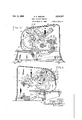
- My present invention relates to printing and vertical section taken from front to rear and more particularly to small portable devices, such viewed from the same side as that of Fig. 2 but as are used in business establishments for printenlarged, the printing parts being in normal ing upon the designated line the cash amounts or inoperative position;
- Fig. 4 is a view similar to Fig. 3 on the same 5 to do with check writing machines of this charscale partly broken away and directionally reacter in which a plurality of movable printing versed, showing the printing couple in operative types are individually adjustable to collectively position, that is, with the operating handle actuproduce different amount combinations, such inated to produce an impression on the check;
- FIG. 5 is a view similar to that of Fig. 4 further 10 by hand levers or keys that the operator moves broken away but showing the type setting means to a selected point with the aid of calibrations in a different position of adjustment; upon an outside scale.
- Fig. 6 is a view similar to Fig. 5 but showing been so set a platen is brought into engagement the positions of the parts when the operating therewith through the medium of a general oplever is actuated, Fig. 5 showing the latter in 15 erating member so that the printing act is acnormal position; complished in the pre-selected denomination.
- Fig. 7 is a fragmentary detail front and top It is sometimes desired to repeatedly print checks View, partly in section, of the key mechanism of the same amount and it is at other times and the clearing yoke;
Description
Feb. 11, 1941. H. c. WELTER CHECK WRITING MACHINE Filed March 15, 1939 4 Sheets-Sheet l INVENTOR. C.' Judie/ Feb. 11, 1941. H. c. WELTER 2,231,237
annex WRITING MACHINE I Filed March 15, 1939 4 Sheets-Sheet 2 I ly/ IN VENTOR.
Feb. 11, 11. H. c. WELTER CHECK WRITING MACHINE 4 Sheets-Sheet 3 Filed March 15, 1939 INVENTOR. C ZU eZZEZ' TORNEY.
Feb. 11, 1941. H. c. WELTER 1,
CHECK WRITING MACHINE Filed March 15 1939 4 Sheets-Sheet 4 INVENTOR. Herr/2a Zdqll UNITED STATES PATENT CHECK WRITING MACHINE Herman G. Welter, Rochester, N. Y., assignor to Hall-Welter Co. Incorporated, Rochester, N. Y., a corporation of New York Application March 15, 1939, Serial No. 261,995
Claims. (01. 101-20) My present invention relates to printing and vertical section taken from front to rear and more particularly to small portable devices, such viewed from the same side as that of Fig. 2 but as are used in business establishments for printenlarged, the printing parts being in normal ing upon the designated line the cash amounts or inoperative position;
5 of checks. The invention has more particularly Fig. 4 is a view similar to Fig. 3 on the same 5 to do with check writing machines of this charscale partly broken away and directionally reacter in which a plurality of movable printing versed, showing the printing couple in operative types are individually adjustable to collectively position, that is, with the operating handle actuproduce different amount combinations, such inated to produce an impression on the check;
dividual adjustment of the types being effected Fig. 5 is a view similar to that of Fig. 4 further 10 by hand levers or keys that the operator moves broken away but showing the type setting means to a selected point with the aid of calibrations in a different position of adjustment; upon an outside scale. When the types have Fig. 6 is a view similar to Fig. 5 but showing been so set a platen is brought into engagement the positions of the parts when the operating therewith through the medium of a general oplever is actuated, Fig. 5 showing the latter in 15 erating member so that the printing act is acnormal position; complished in the pre-selected denomination. Fig. 7 is a fragmentary detail front and top It is sometimes desired to repeatedly print checks View, partly in section, of the key mechanism of the same amount and it is at other times and the clearing yoke;
in desired to change the amount printed on the Fig. 8 is a fragmentary detail directionally check between operations. reversed illustrative of the slip-01f connection It is the latter requirement with respect to between the actuating element of the clearing -which the present invention has to do and its device and the main operating element;
rr c
general object is to provide a simple and effec- Fig. 9 is a bottom plan View of the machine, tive means for restoring the individual types and 25 to a zero or neutral position so that after the Fig. 10 is a vertical section from front to rear operating member has performed its function through the base thereof showing, in comparithe setting devices will be restored and, as in son with Fig. 2, the action of the vacuum cups the previous setting, they may be moved to print in their function of holding the machine to the a new and different amount when the general desk table or other support. 30 operating element is again brought into use. Similar reference numerals throughout the More particularly, an Object of the present several views indicate the same parts. 7 invention is to provide a mechanism of this char- A known check riting machine t which my of p fif Constructlon in Which a present improvements are applicable is disclosed setting or clearing means for the type setting in my prior patent 1 959,135 dated May 15, 35
keys hugs the latter at all times so that, after 1934. The general structure of that machine has the printing operation, it is motivated without been reproduced to some extent in the aeeom impact and hence reduces the noise and wear panymg drawings and requires descnption hereincident to the actuatlon of such an element in in only insofar as Such description will aid in structures where it is normally held in a far position and is then released or motivated to undelstandmg the addltlons tpmvements 40 perform the clearing operation. To these and that. I have now In tms mew-and re other ends, the invention resides in certain imferrmg partmularly to t .drawmgs i provements and combinations of parts, all as to Flgs' 1 2 thereof I intimates a casing will be hereinafter more fully explained the d1v1ded by a horizontal slot 2 lnto a lower base 45 novel features being pointed out in the claims Portion 3 and an upper housing overhanging at the end of this specificatio breast portion 4. The base portion 3 is provided In the drawings: with a table plate 5 constituting the bottom of Fig. 1 is a top plan view of a, h k it the slot. In the printing of a check, the latter 5 machine constructed in accordance with and is laid upon the table, thrust back into the slot illustrating one embodiment of my invention; and y m n of a p v b gauge m 6 Fig. 2 is a side elevation thereof viewed from positioned so that with the aid of a pivoted line the side of the main operating lever, namely, the gauge I the printing impression through the deright side; vices hereinafter described may be accurately Fig. 3 is a substantially central longitudinal placed on the amount line of the check. This 55 the return movement of this operating lever that accomplishes that result.
In the general operation of the machine, when the operating lever 26 is brought forward from the position of Figs. 1, 2, 3 and 5, it being assumed that appropriate types on the various segments 9 have been brought into the printing line opposite the impact of the platen l5, the latter is raised from the position of Fig. 3 to that of Fig. 4 in the ordinary manner through the mechanical connections previously described. This forward movement of the operating lever is an idle one so far as the draw bar 38 is concerned because the plate on the same operating shaft 22 and its pin 36 is moving forwardly on the riding surface 46. The limit of the forward movement of such operating crank 20 is shown in Figs. 4 and 6. The arrival at this forward position results in the forward advance of pin 36 on member 35 on the operating shaft 22 and the dropping of draw bar 38 to the extreme low position of Fig. 4, incidentally bringing shoulder 4| on the draw bar in the direct path of such pin 36 on its return. When the latter so. returns with the operating lever, it engages and interlocks with shoulder 4| on the draw bar, as shown in detail in Fig. 8, dragging the latter rearwardly and with it the clearing yoke 33--34 which it positively actuates in this respect. The result is that the clearing and resetting yoke picks up successively or simultaneously, according to their previous adjustment, all of the radial key levers 28 of the various type segments and thrust them back to the normal position of Figs. 3 and 5 augmented by the action of the yoke spring 51 or at least not opposed thereby. When such a sufficient actuation of the draw bar has been accomplished, the
length of the riding surface and its relation to the shoulder 4| in agreement with the movement of the pin 36 is such that just as the draw bar, through its wrist pin connection 31, carries the clearing yoke 3334 to restore the type keys and levers to neutral position, the pin 36 rides below the shoulder 4| in the pins downward and rearward movement and automatically disconnects itself from further affecting the attained result of restoring the keys and key arms with the clearing yoke 34 still mildly engaging the same under the impulse only of its own weak actuating spring 51. This is another way of stating that the draw bar 38 through its wrist pin connection 31 with the clearing yoke 3334 disconnects from the latter when the same has restored the key and type arms to normal neutral or zero positions.
To positively disengage pin 36 from shoulder M of draw bar 38 at the conclusion of the effective movement of the latter on the return of the operating crank so that clearing yoke 34 will come to rest against the type setting arms 28 of the keys 2'! in their neutral or zero position, there is also mounted on plate 35 carrying pin 36 a dog 42 in the form of an adjustable slotted plate secured by a screw 43 to a flange 44 bent laterally from the said plate, by means of which screw and slotted connection the dog 42 may be advanced radially from the axis of operating shaft 22. Surface 46 beforementioned on draw bar 38 lies in the path of this dog. The dogs projection, so regulated by screw 43, causes it to engage surface 40 and causes pin 36 on plate 35 to slip out of engagement with shoulder 4| on the draw bar at the proper point. The idea is that this adjustment shall be so made that pin 36 will keep positive contact with shoulder after the printing operation.
4| on the draw bar until the latter has returned setting levers 28 to just the right point and thereupon totally relieve draw bar 38 from pin 36 so that the latter may ride under shoulder 4| and across an under surface 45 on the rear extremity of the draw bar. In other words, when the operating lever 20, on such an adjustment, moves forwardly to an extreme position, it merely accomplishes the printing operation. When it moves rearwardly, it picks up its actuator 38 otherwise idle and accomplishes the result stated.
It is sometimes desired to repeatedly print a number of checks of the same denomination, as, for instance, in a simple illustration, where a number of employees are being given a pay check of the same amount, say, $25. In that case, it is obvious that the operator should not be required to reset the amount keys 2'! back to $25 after printing each check but should be allowed repeated actuation of the main operating lever to produce on successive checks replications of the same amount as may be required To take care of this, I provide a simple means ,for rendering the resetting yoke 34 inoperative at the will of the operator by temporarily holding draw bar 38 out of all contact with the operating mechanism on the return of operating lever 20 This consists, in the present instance, of a dog 46 (Figs. 5 and 6) mounted to turn in a wall of the upper casing 4 on the right side of the machine adjacent the operating lever 20. Externally, it is provided with a finger piece 41 (Fig. 2) by means of which it may be adjusted by the operator between the positions of Figs. 2 and 5 and that of. Fig. 6. On the interior, it has a laterally and inwardly turned flange 48 adapted to engage beneath the draw bar 40, heretofore deing are to occur, finger piece 47 is rocked rearwardly to the position of Fig. 6.
Thereupon when draw bar 40 moves under the influence of the operating lever in either direction, it is held raised against the tension of its Spring 39 by the flange 48 of the do and is rendered idle and ineffective so that the pin 36 on member 35 of the operating shaft 22 cannot reach the shoulder 4| and cause the draw bar to actuate the clearing yoke.
The rubber vacuum cup 66 shown attached to the base element 3 and floor plate 6| thereof in Figs. 9 and 10 are for the purpose of insuring such contact with a table or desk that the manipulations of the operating crank 20 will not disturb the position of the machine.
In a check writing machine provided with a clearing yoke constructed in accordance with my invention, the following points are to be noted: the clearing or resetting yoke at all times hugs the arms of the setting keys for the type segments; it is displaced or retarded by the keys as they are advanced or by the key that is advanced to the greatest degree and when such clearing yoke is picked up by the actuating devices connected to the main operating means, it makes no noisy impact with the key or key arms but is positively actuated from that point in the same direction that its individual sprin 5'! is normally urging it.
. Lolainr as my invention:
.1. in a check writing machine, thecombinationr with a printing couple embodying a plural- 'ity of movable types individually adjustable to produce, collectively, diiferent amount combinations, a platen movable toward and from a printing line on which said types are so assembled and a plurality of operating keys for said types selectively movable out of alinement with one another to effect such amount combinations on the said printing line, and means for so operating the platen, of a resetting device for the keys adapted to restore them all to a neutral position, means constantly urging said resetting device to remain normally in contact with the most advanced key, and actuating means connecting the said device with the opera-ting means.
2. In a check writing machine, the combination with a printin couple embodying a plurality of movable types individually adjustable to produce, collectively, different amount combinations, a platen movable toward and from a printing line on which said types are so assembled and a plurality of operating keys for said types selectively-movable out of alinement with one another to effect such amount combinations on the said printingline, and means for so operating the platen, of a resetting device for the keys- I adapted to restore them all to a neutral position, a spring normally urging said device toward the keys in a direction tending to clear thesame and normally maintaining the resetting device in contact with the most advanced key, and actuating means for the device having aslip-off-connection with the, operating means to be motivated thereby on the return movement-of the latter.
3. 'In a check writing machine, the combination with a printing couple embodying a plurality of movable types individually adjustable to produce, collectively, different amount combinations; a platen movable toward and from a printing lineon which said types are so assembled and-a pluralityof operating keys for said types .selectively movable out of alinement with one another to effect such amount" combinations on the said printin line;and means for so operating the platen, of a resetting device for the keys adapted to restore them to a neutral position and comprising a yoke, a spring normally maintaining. said yoke in a clearing position by .maintaining the, same'in contact with the most advanced. key, .a draw bar pivoted to the yoke to actuate the same, and a device on the operat- :ing: means arranged to temporarilyengage and motivate the draw bar and then slip ofi from and-release the same, said yoke being at all times in contact with one or more of said keys.
4. In a check writing machine, the combination with a printing couple embodying a plurality of movable type segments mounted to turn on a common axis and individually adjustable toproduce, collectively, different amount combinations, a platen movable toward and from .a printing line -on' which said types are so assembled, a plurality of operating keys for said types embodying radially extending arms on the segments selectively movable out of alinement with one another to effect such amount combinations on the'said printing line, and means for so operating the platen, of a resetting device for the keys adapted to restore them to a neutral cleared position-and comprising a swing- .ing yoke spanning the'paths of the key arms and adapted to be displaced by the contact of a key-arm as the latter is advanced from neutral position in the setting of the types, means con- .to produce, collectively, different amount combinations, a platen movable toward and from a printing line on which said types are so assembled, a plurality of operatin keys for said types embodying radially extending-arms on the seg- -ments selectively movable out of alinement with one another to effect such amount combinations on the said printing line, and means'for so operating the platen, of a'resetting device for the keys adapted to restore them to a neutral cleared position and comprising a swinging yoke spanning the paths of'the key arms and adapted to-be displaced by'the contact of a key arm as the latter is advanced from neutral position in the setting of the types, a spring constantly urging the yoke against the-most advanced of the key-arms but of insuf icient strength to alone "displace the same, and actuating means for the yoke motivated by the return movement of the operating means to restore the yoke and all of the keys to normal and neutral positions.
HERMAN C. WELTER.
Priority Applications (1)
| Application Number | Priority Date | Filing Date | Title |
|---|---|---|---|
| US261995A US2231237A (en) | 1939-03-15 | 1939-03-15 | Check writing machine |
Applications Claiming Priority (1)
| Application Number | Priority Date | Filing Date | Title |
|---|---|---|---|
| US261995A US2231237A (en) | 1939-03-15 | 1939-03-15 | Check writing machine |
Publications (1)
| Publication Number | Publication Date |
|---|---|
| US2231237A true US2231237A (en) | 1941-02-11 |
Family
ID=22995741
Family Applications (1)
| Application Number | Title | Priority Date | Filing Date |
|---|---|---|---|
| US261995A Expired - Lifetime US2231237A (en) | 1939-03-15 | 1939-03-15 | Check writing machine |
Country Status (1)
| Country | Link |
|---|---|
| US (1) | US2231237A (en) |
Cited By (7)
| Publication number | Priority date | Publication date | Assignee | Title |
|---|---|---|---|---|
| US2517354A (en) * | 1946-11-13 | 1950-08-01 | Walter A Eaton | Check writer |
| US2604040A (en) * | 1947-06-16 | 1952-07-22 | Lloyd H Fenstermaker | Check protector |
| US2697981A (en) * | 1950-08-30 | 1954-12-28 | Theodore B Hirschberg Jr | Check writing machine |
| US2707432A (en) * | 1950-12-16 | 1955-05-03 | Theodore B Hirschberg Jr | Machine for writing checks |
| US2794387A (en) * | 1953-03-25 | 1957-06-04 | Victor Adding Machine Co | Platen impelling means in check writers |
| US2878749A (en) * | 1956-01-27 | 1959-03-24 | Theodore B Hirschberg Jr | Checkwriter |
| US3025787A (en) * | 1962-03-20 | Data registering and marking machine |
-
1939
- 1939-03-15 US US261995A patent/US2231237A/en not_active Expired - Lifetime
Cited By (7)
| Publication number | Priority date | Publication date | Assignee | Title |
|---|---|---|---|---|
| US3025787A (en) * | 1962-03-20 | Data registering and marking machine | ||
| US2517354A (en) * | 1946-11-13 | 1950-08-01 | Walter A Eaton | Check writer |
| US2604040A (en) * | 1947-06-16 | 1952-07-22 | Lloyd H Fenstermaker | Check protector |
| US2697981A (en) * | 1950-08-30 | 1954-12-28 | Theodore B Hirschberg Jr | Check writing machine |
| US2707432A (en) * | 1950-12-16 | 1955-05-03 | Theodore B Hirschberg Jr | Machine for writing checks |
| US2794387A (en) * | 1953-03-25 | 1957-06-04 | Victor Adding Machine Co | Platen impelling means in check writers |
| US2878749A (en) * | 1956-01-27 | 1959-03-24 | Theodore B Hirschberg Jr | Checkwriter |
Similar Documents
| Publication | Publication Date | Title |
|---|---|---|
| US2231237A (en) | Check writing machine | |
| US2756926A (en) | Dodsworth | |
| US2142862A (en) | Check writer | |
| US3183829A (en) | Check writing machine | |
| US1400574A (en) | steele | |
| US2121967A (en) | Cash register | |
| US3139169A (en) | Printing machine record sheet holder | |
| US2320810A (en) | Typewriting machine | |
| US1583102A (en) | Adding and listing machine | |
| US2336111A (en) | Tabulating machine | |
| US2104051A (en) | Calculating machine | |
| US2180446A (en) | Check writing machine | |
| US2211680A (en) | Check writer | |
| US2658447A (en) | Positive cam operated print mechanism | |
| US916589A (en) | Recording mechanism. | |
| US1225655A (en) | Adding and recording machine. | |
| US1864228A (en) | A cobpobation of maeyland | |
| US936652A (en) | Computing and recording machine. | |
| US3780649A (en) | Decimal-point printing mechanism for electronic calculator | |
| US2758785A (en) | Hvventdrs | |
| US2099123A (en) | Combined typewriting and computing | |
| US1949741A (en) | Calculating machine | |
| US988700A (en) | Adding-machine. | |
| US1943828A (en) | Check writer | |
| US2203116A (en) | Cash register |