US2230188A - Process of and apparatus for forming articles from plastic material - Google Patents
Process of and apparatus for forming articles from plastic material Download PDFInfo
- Publication number
- US2230188A US2230188A US198646A US19864638A US2230188A US 2230188 A US2230188 A US 2230188A US 198646 A US198646 A US 198646A US 19864638 A US19864638 A US 19864638A US 2230188 A US2230188 A US 2230188A
- Authority
- US
- United States
- Prior art keywords
- mold
- nozzle
- plastic material
- molds
- shaft
- Prior art date
- Legal status (The legal status is an assumption and is not a legal conclusion. Google has not performed a legal analysis and makes no representation as to the accuracy of the status listed.)
- Expired - Lifetime
Links
Images


Classifications
-
- B—PERFORMING OPERATIONS; TRANSPORTING
- B29—WORKING OF PLASTICS; WORKING OF SUBSTANCES IN A PLASTIC STATE IN GENERAL
- B29C—SHAPING OR JOINING OF PLASTICS; SHAPING OF MATERIAL IN A PLASTIC STATE, NOT OTHERWISE PROVIDED FOR; AFTER-TREATMENT OF THE SHAPED PRODUCTS, e.g. REPAIRING
- B29C49/00—Blow-moulding, i.e. blowing a preform or parison to a desired shape within a mould; Apparatus therefor
- B29C49/02—Combined blow-moulding and manufacture of the preform or the parison
- B29C49/04—Extrusion blow-moulding
-
- B—PERFORMING OPERATIONS; TRANSPORTING
- B65—CONVEYING; PACKING; STORING; HANDLING THIN OR FILAMENTARY MATERIAL
- B65D—CONTAINERS FOR STORAGE OR TRANSPORT OF ARTICLES OR MATERIALS, e.g. BAGS, BARRELS, BOTTLES, BOXES, CANS, CARTONS, CRATES, DRUMS, JARS, TANKS, HOPPERS, FORWARDING CONTAINERS; ACCESSORIES, CLOSURES, OR FITTINGS THEREFOR; PACKAGING ELEMENTS; PACKAGES
- B65D1/00—Containers having bodies formed in one piece, e.g. by casting metallic material, by moulding plastics, by blowing vitreous material, by throwing ceramic material, by moulding pulped fibrous material, by deep-drawing operations performed on sheet material
- B65D1/02—Bottles or similar containers with necks or like restricted apertures, designed for pouring contents
- B65D1/0223—Bottles or similar containers with necks or like restricted apertures, designed for pouring contents characterised by shape
- B65D1/023—Neck construction
Definitions
- PROCESS or AND APPARATUS FOR FORMING ARTICLES FROM PLASTIC MATERIAL E. T. FERNGREN Filed March 29. 1938 l5 Sheets-Sheet 3 1% v e w 2 0 7' E%007/ 7i'e?;97fe% fliiomegs Jan. 28, 1941. a. T. FERNGREN PRGCESS OF AND APPARATUS FOR FORMING ARTICLES FROM PLASTIC MATERIAL Filed llarch 29, 1958 I 15 Sheets-Sheet 4 flzvzgren w w-AM Jan, 28, 1941. a. 'r.
- This invention relates to a process of and apparatus for forming articles from plastic ;material, and more particularly to the forming of hollow blown articles, such as bottles, from organic plastic material which is temperaturesensitive and which at normal temperatures is hard, but which may be rendered fluent, plastic and moldable at elevated temperatures and thereafter may be rigidified in a suitable manner.
- plastic material and particularly organic plastic material
- plastic material may be treated first to convert or bring it to a plastic and moldable condition, then to form it into an article of the 25 desired shape, and more particularly to form it into a hollow blown article by a process including extruding the material from a suitable orifice of a nozzle as a closed-ended hollow body and thereafter blowing this body to conformity with 30 the cavity of a suitable mold.
- the article thus formed must then be rigidified, by cooling, in the case of thermoplastic materials, such as cellulose acetate, or by some other process, for example, heating, in the case of thermo-setting materials, such as many condensation products now well known -in the plastic art.
- a further object of the invention is to provide a process and apparatus by which the material, once it has been suitably brought to a 40 plastic and moldable condition, may be handled, first to move a selected and to a certain extent a variable amount of it from the original supply body or plasticating means to andthrough a nozzle in preparation for the forming of an article, and in this connection to provide a means by which the material maybe extruded from a parent supply body in a nozzle or like means, through an orifice at a pressure independent of such pressure as may be used on the material in converting it to a plastic and moldable condition.
- a further object of the invention is to provide a suitable extrusion nozzle, preferably comprising spaced inner and outer nozzle members, pro- 55 viding a tubular passage therebetween, in which means by which the material therein may be-subjected preferably both internally and externally to suitable temperatures, so as to maintain it at the desired viscosity during its formation as a tubular body and during its extrusion from the nozzle.
- a further object of the invention is to provide for the closing of the leading end of a tubular body of plastic material contained Within a nozzle of the character above set forth so as to form the material into a closed-ended hollow body which may thereafter be extruded from the nozzle and expanded by internally applied pneumatic pressure to conformity with a mold.
- a further object of the invention is to provide for the expansion of such a closed-ended hollow body, as aboveset forth, in a mold by the use of internally applied pneumatic pressure so as to form an article of the desired shape in the mold, which will have a selected wall thickness or variation in wall thicknesses throughout. It is sometimes advantageous to project the extrusion nozzle into the mold to a selected extent, either to form a closed end for the tubular hollow body within the nozzle in conjunction with the bottom wall of the mold or to assist in the expansion of the material by extruding the material and expanding it against the wall of the mold while simultaneously and progressively causing such a relative movement between the nozzle and the mold as in effect to move the nozzle outwardly from the mold during the extrusion and expansion of the plastic material.
- a further object of the invention is to provide for the establishment of a. suitable and selected back pressure within the mold, during the expansion of the closed-ended hollow body of plastic material therein by selectively establishing pressure or vacuumconditions or a restricted venting of the air in the mold to the atmosphere, inaccordance with the expansion characteristics of the particular material beinghandled.
- a further object of the present invention is to provide suitable means for severing an article formed in a mold as aforesaid from the parent body of plastic material from which that article is made and which parent body remains in an extrusion nozzle.
- a further object of the present invention is to provide in connection with the making of bottles by a process and! or apparatus as above set forth, for the forming of finished an reinforced neck portions for the bottles so made and preferably also to provide for the forming of a bottle in one mold simultaneouslyi with the finishing of the neck of another bottle in another mold.
- a further object of the present invention is to provide apparatus for carrying out the various process steps above outlined, and particularly apparatus providing a plurality of molds having means for moving them in respect to an extrusion nozzle and for bringing them successively into alignment with the nozzle and thereafter with neck finishing means, and also to provide novel apparatus by which the molds may be suitably opened and closed at the desired times in th cycle of the apparatus as a whole.
- Figure 1 is a view principally in side elevation of an entire machine, but showing the means for bringing the plastic material to a moldable condition in vertical'section, and also having certain other portions of the machine broken away to' show the interior construction;
- Fig. 2 is a front elevation of the entire machine
- Fig. 3 is a plan view thereof
- Fig. 4 is a view substantially in plan of the mold table with the molds thereon, a portion of the table being broken out in view of space requirements;
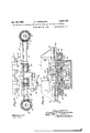
- Fig. 5 is a view principally in front elevation of the mold table of Fig. 4 and certain of the operatin .means associated therewith, some portions of the structure being broken awayand shown in vertical section; 7
- Fig. 6 is a view substantially in transverse vertical section on the line 6-6 of Fig. 4;
- Fig. '7 is a fragmentary view substantially in horizontal section on the line
- Fig. 8 is a somewhat similar view substantially in horizontal section on the line 8-8 of Fig. 1, some parts being further broken away to show the interior construction;
- Fig. 9 is a fragmentary view substantially in vertical section on the line 99 of Fig. 8, illustrating the forming of a bottle in a mold'and the shearing mechanism and its operating means for severing a formed bottle from the plastic material remaining in the nozzle;
- Fig. 10 is an inverted plan view of the shearing mechanism with parts in horizontal section taken substantially on the line l0l ll of Fig. 9; a
- Fig. 11 is a view in transverse vertical section substantially on the line ll--Il of Fig. 10, showing also the means for supporting the shear housing during the movement of the molds to their those portions shown in Fig.- 13, illustrating the relation of the nozzle parts to a mold during the forming oi an'article according to one process which may be carried out in the machine;
- Fig. 15 is a fragmentary view partly in perspective and partly in central vertical section illustrating the construction of the lower endof the nozzle of Fig. 14;
- Fig. 16 is a view in transverse horizontal section of the lower end portion of the nozzle, taken on the line l6-l6 of F18. 14;
- Fig. 17 is a somewhat diagrammatic fragmentary view in vertical section illustrating a modified form 01' nozzle and -one way in which the end of a hollow body of plastic material therein may be closed;
- Fig. 18 is a diagrammatic view, principally in vertical section, illustrating a nozzle somewhat similar to that shown in Fig. 17- and illustrating one way of forming an article in a mold by exthe outer nozzle member;
- Fig. 21 is a fragmentary plan view showing the variations which may be made inthe operating mechanism at thetop of the machine to accommodate this mechanism to the operation of the device shown in Fig. 20;
- Fig. 22 is a more or less diagrammatic detail view partly in vertical section and partly in elevation illustrating the means for opening the molds and showing different positions of these means during the mechanical cycle of the apparatus;
- Fig. 23 is a view in vertical section of the valve for controlling the pneumatic pressure within the nozzle
- Fig. 24 is a side-elevation of the rotatable member of the valve shown in Fig. 23; I
- Fig. 25 is a fragmentary view partly in elevation and partly in vertical section of the means for supporting the molds and certain of the operating means for the molds;
- Figs. 26, 2'7 and 28 are diagrammatic view illustrating different stages in a cycle of forming bottles according to one process which may be practiced by the machine shown in the preceding figures, Fig. 26 showing the end of the tubular body of plastic material closed above a shearing means and retracted therefrom by the internal application of vacuum, Fig. 27 showing the nozzle introduced a substantial distance into the mold and a hollow body of plastic material being extruded and blown from the nozzle against the bottom and sides of the mold, and Fig. 28 showing'in dotted lines an intermediate position and in full lines the bottle completely formed and severed from the parent body of plastic material within the nozzle;
- Fig. 29 is a view following the stage of the process shown in Fig. 28 and illustrating the shifting of the molds, the view being in side elevation and diagrammatic as to the molds and in central vertical section as to the nozzle and certain associated means and Figs. 30, 31 and 32 are another series of diagrammatic views illustrating an article being formed in the other of the pair of molds of Figs. 26 to 28 and by a somewhat different process,
- Fig. 30 illustrating the nozzle at the upper end of the mold and having a closed-ended hollow body of plastic material therein
- Fig. 31 the closedended hollow body of plastic material extruded from the nozzle almost to the full length of the mold, but without substantial lateral distention
- the plastic material which is rendered fluent, plastic and moldable by the means shown, or by some other means, is introduced into the machine which particularly forms a subject matter of this invention from an apparatus point of view and into an extrusion nozzle of that machine.
- the plasticating means or means for bringing the material to a plastic and moldable condition is substantially continuously operated and the means for utilizing the material by extrusion and blowing as hereinafter set forth is intermittent in its operation, means are provided for accommodating the irregularities between the supply and the use of the material.
- Means are further provided for segregating measured quantities of the material, each such quantity being that required in forming a single article. These quantities are extruded into a parent supply body of the material in the extrusion nozzle, which may contain an amount of plastic material either greater or less than one of said quantities.
- the material as thus brought to the extrusion nozzle is maintained in a tubular form between inner and outer nozzle members, which are spaced apart to provide a tubular passage for the plastic material and which are provided with means for supplying heat to the material 'to maintain it at a desired condition of plasticity or viscosity.
- Means are preferably provided in conjunction with the nozzle for extruding the plastic material therethrough at a pressure independent of the pressure exerted on the material by the plasticating means as aforesaid. In the present instance this means is also employed in obtaining the searegated measured quantities of the plastic material as aforesaid.
- the next operation in the forming of hollow articles, such as bottles, is to form a closed end for the tubular body of plastic material in the nozzle. This may be done in several ways as hereinafter set forth and usually is done at the extrusion orifiee or discharge end of the nozzle.
- this closed-ended hollow body may be extruded and directly expanded against the wall of a mold cavity by the introduction of the nozzle into the mold cavity to a point adjacent to the bottom thereof followed by the gradual withdrawal of the nozzle during the extrusion and blowing, or may be extruded to substantially the full length of the mold from a nozzle having its orifice at the top thereof and thereafter expanded. I contemplate that intermediate processes between these two extremes may be used.
- a plurality of molds are provided which are brought successively into alignment with the extrusion nozzle, so that articles may be formed therein by extrusion and blowing as aforesaid, which articles are completely formed while remaining integral with the parent body of plastic material within the nozzle.
- two molds mounted on a laterally reciprocating table and brought alternately into alignment with the extrusion nozzle.
- the completed articles within the molds are severed from the parent body of plastic material and the neck portions thereof (in the case of bottles) are finished, in this case by folding inwardly the top periphery or brim at the neck of the article onto the contiguous portion therebeneath to form a reenforced neck or lip portion for the bottle. This is done in one mold during the forming of a succeeding article in the other mold.
- the machine is mounted upon a base I and comprises a stationary structure including a lower housing 2 and upper housing 3, which are rigidly connected to each other and to the base I.
- a base I and the housing 2 Mounted on the base I and the housing 2 are means supporting a pair of molds 4 and 5, which are movable vertically and also laterally reciprocable to bring them alternately to a central forming position by means and in a manner hereinafter described.
- the upper housing 3 is provided with a pair of bracket lugs 6 and I, Fig. 1, in which is rotatably mounted a vertical shaft 8. Pivoted on the shaft comprising a rack l3 secured to a rear panel.
- knurled lock nut i8 may be threaded on the shaft l6 and arranged to be tightened against the ad- 'jacent bearing member for the shaft. Endwise movement of the shaft is prevented by suitable collars and set screws I 9.
- the support I0 is adapted to carry a means generally indicated at 20, Fig. 1, for plasticating the material or bringing it to a fluent and moldable condition, this means being shown as supported upon asuitable supporting means 2!, which may be supported from the support ill, or if desired some other suitable support (not shown).
- is preferably supported from the support It in order to permit the vertical movement of this support with the bracket 9, as hereinafter set forth. However, if this vertical movement is omitted as may be done, the means 29 may be separately supported.
- the support III also carries a nozzle generally indicated at 22, Fig. 14, through whichthe plastic material is adapted to be extruded in forming articles as hereinafter set forth. Means are also provided for extruding the material through the nozzle and for controlling the flow of the material into and from the nozzle, as set forth in detail hereinafter. 1
- Means are provided for holding the bracket 9 and parts carried thereby in the full line position
- bracket portions 24, Figs. 1, 7 and 8, comprising bracket portions 24, Figs. 1, 7 and 8,
- a bracket portion 21, Figs. 2 and '7 which may be integral with the bracket 9 and which is provided with a slotted portion 28 at its outer end, may be secured to the upper housing 3 by means of a swing bolt 29 and a thumb screw 30.
- This arrangement serves to prevent the means carried by the bracket 9 from swinging back toward their normal or operative position during the making of repairs on subjacent mechanism. In order to permit this swinging movement, however, it is necessary to remove the screws 26, which may be easily done.
- a source of power here shown as an electric motor 3
- the bracket 9 is made ,swingable about the vertical axis of the shaft 8
- the molds 4 and 6, as best shown in Figs. 4, 5 and 6, are mounted upon a laterally reciprocable and vertically movable table 34, and are each made in two complementary halves slidable on the table toward and from each other.
- the mold 4 is provided with.horizontal slide members 35 and 36 and the mold 6 with similar slide members 31 and 38.
- slide members are mounted in slideway-forming means 39, 49, 4
- the table 34 is provided on its underside with laterally extending slide portions 44, Fig. 6. which are arranged to slide in dovetailed grooves 46 formed in a support 46.
- the support 46 has secured thereto a pair of downwardly extending guide rails 41, Figs. 1, 2 and 25, which are adapted to slide in guideways formed in a pair of brackets 48 secured to the lower housing 2 and in a second pair of brackets 49 secured to the base I.
- Means are provided for moving the molds vertically.
- the means move not only the molds, but also the table 34- and the'support 46.
- the support 46 is provided,--
- the moldtable 34 is provided with a pair of guide members 60, Figs. 4 and 5, arranged at right angles to the guide members 44.
- Slidablymounted in the guide members 60 is a slide block 6
- the pin 62 is rigidly mounted in the outer end of a crank arm 63 which is secured by a split collar connection 64 to the upper end of a vertically disposed rotatable shaft 65.
- the shaft 65 is suitably .iournaled in bearing members in the support 46, Figs.
- the shaft 52 also carries secured theretoa disc 68 provided with four radial slots 69, Figs. 1 and 2, this disc being the is mounted on a rotatable shaft 12 which is jour-.
- the shaft 12 carries a beveled gear 18 meshing with a similar beveled gear 16 mounted on a shaft 11 which is journaled in a bra ket 18 secured to the base I within the housing 2.
- the shaft 11 also carries secured thereto a sprocket wheel 18 which is driven by a sprocket chain 88 from a sprocket wheel 8
- the ratios of the sprocket wheels 8I and 18 and the gears 18 and 16 are such that the shaft 12 makes one revolution for each revolution of the shaft 33.
- the disc 18 will similarly make a single revolution during the making of each article.
- the shaft 52 will make a quarter revolution for each revolution of the main drive shaft 33; and as the ratio of the gears 61 and 66 is two to one, the shaft 65 will make a half revolution during each revolution of the drive shaft 33 and hence during the formation of eacharticle, so as to rotate the crank arm 63 through 180 and to oscillate the mold table 34 from one end of its path of movement to the other each time an article is made.
- Geneva mechanism has its driven mem ber mounted on the vertically movable support 46, it can only be operated to move the mold table laterally during the time the molds are at their lowermost position, which is at the time the molds are in a position such that they will not interfere with other means, including the extrusion nozzle 22, as hereinafter set forth.
- each of the slides 35, 36, 31 and 38 is provided with a rack, such as shown at 82, Figs. and 6, these racks extending through suitable slots formed in the mold table 34.
- pinions 83, 84, 85 and 86 Meshing with the racks 82 for the slides 35 to 38 respectively are pinions 83, 84, 85 and 86.
- These pinions are mounted on transversely extending shafts 81, 88, 88 and 88 respectively, all of which are journaled in suitable bearings secured to the underside of the mold table 34.
- the shafts 81 to 88 have respectively secured thereto beveled pinions 8
- the beveled pinions 8I to 84 are respectively in mesh with beveled gears 85, 86, 81 and 88.
- the gears 85 and 86 are both mounted on a shaft 88 journaled in the left hand end of the mold table 34; while the gears 81 and 88 are similarly mounted on a shaft I88 journaled in the right hand end of the mold table, Figs. 4 and 5.
- At the forward ends of the shafts 88 and I88 are mounted upstanding crank arms ml and I82 respectively, which have pivotally connected to their outer ends link members I83 and I84 respectively, Figs. 2, 3 and 25, these link members being connected by a suitable tension spring I85.
- the tension of the spring I85 is-effective through the mechanism described to tend to close both molds 4 and 5 when such action is permitted by the mold opening means hereinafter to be described.
- Means are provided for opening the molds during the time they are respectively out of or away from the central forming position. These means are effective, as shown, to open the molds in response to the vertical movement of the mold table as heretofore described, and particularly in response to the lowering of the mold table after it has been raised.
- each of the shafts 88 and I88 are provided with means cooperating selectively with "flxed cams I86 and I81, Figs. 2, 4 and 22, the cams being suitably mounted on brackets extending from the lower housing member 2.
- the means mounted on the shafts 88 and I88 are each similar to the other, but are respectively reversed, as a right and a left hand.
- These means comprise bell crank levers I88 and I88 respectively-secured to the shafts 88 and I88.
- Pivoted to the bell cranks I88 and I88 are bell cranks H8 and III respectively, one arm of each of which carries a cam roller H2 and H3 respectively.
- the bell cranks II 8 and III are respectively pivoted on horizontal axes to the outer ends of one of the arms each of the bell cranks I88 and I88.
- the other arm of the bell crank I88 is connected by a tension spring '4 to the other arm of the bell crank H8; and the second arm of the bell crank III is connected by' a tension spring II5 to the second arm'of the bell crank I88.
- the tension springs H4 and H5 cause a relative movement of the bell cranks to bring them to the full line positions shown-in Fig. 22, such that abutting surfaces of the connected bell cranks are in engagement at II6 and H1 respectively.
- the parts shown in full lines at position A indicate the position of the parts with the mold table at its lowermost and right hand position, as seen also in Fig. 2.' During the raising of the mold table, the parts move through position B to position C.
- the mold table then moves from right to left, as indicated in Fig. 22, from position A to-position E, during which time there will be no rota
Description
Jan. 28, 1941. E. T. FERNGREN 2,230,188
PROCESS OF AND APPRATUS FOR FORMING ARTICLES FROM PLASTIC MATERIAL Filed March 29, 1938 15 Sheets-Sheet l Ez 'ql.
JanQ28, 1941. E. -r. FERNGREN 88- PROCESS OF AND APPARATUS FOR FORMING ARTICLES FROM PLASTIC MATERIAL Filed March 29, 1938 15 Sheets-Sheet 2 E 1%}:37220? m0 e 78% Wz'ifieas 4 Jan. 28, 1941. 2,230,188
PROCESS or AND APPARATUS FOR FORMING ARTICLES FROM PLASTIC MATERIAL E. T. FERNGREN Filed March 29. 1938 l5 Sheets-Sheet 3 1% v e w 2 0 7' E%007/ 7i'e?;97fe% fliiomegs Jan. 28, 1941. a. T. FERNGREN PRGCESS OF AND APPARATUS FOR FORMING ARTICLES FROM PLASTIC MATERIAL Filed llarch 29, 1958 I 15 Sheets-Sheet 4 flzvzgren w w-AM Jan, 28, 1941. a. 'r. 'FERNGREN vPROCESS QF AND APPARATUS FOR FORMING ARTICLES FROM PLASTIC MATERIAL Filed March 29, 1938 15 Sheets-Sheet 5 Jan. 28, 1941. E. -T. FERNGREN PROCESS OF AND APPARATUS FOR FORMING ARTICLES FROM PLASTIC MATERIAL Fi led March 29, 1938 15 Sheets-Sheet 6 .zlkzveraifor E72072 T Fewngrem 5 z M Jan. 28, 1941; v E. T. FERNGREN PROCESS OF AND APPARATUS FOR FORMING ARTICLES FROM PLASTIC MATERIAL 15 SheetS- -Sheet 7 Filed March 29, 1938 Jan. 28, 1941. a. 'r. FERNGREN 2,230,188
. PR OCESS 0 F AND APPARATUS FOR FORMING ARTICLES FROM PLASTIC MATERIAL Filed March 29, 1938 15 Sheets-Sheet 8 bbm, NNJ m MVN a T. FERNGREN 2,230,188
PROb-ESS OF AND APPARATUS FOR FORMING ARTICLES FROM PLASTIC MATERIAL Jan. 28, 1941.
I Filed March 29 1938 15 Sheets-Sheet 1O Ill Ilv rll-IIIFIII T W22 i? ess Wzyfgw Jan. 28, 1941. E. T FERNGREN 7 2,230 188 PROCESS OF AND APPARATUS FOR FORMING ARTICLES FROM PLASTIC MAT-ERIN Filed March 29, 1938 15 Sheets-Sheet ll .Jan. 28, 1941. E. T. FERNGREN 2,230,183
BRQ CESS 01 APPARATUS FOR FORMING ,ARTICLES FROM PLASTIC MATERIAL Filed March 29, 1958 15 Shets-Sheet 12 /44 I72 tea II!lilllllillflflllllfflllllllllllllrill!!!IIIIII/Illlllfllill 9! $11.28, 1941. E. 'r. FERNGREN PROCESS OF AND APPARAT US FOR FORMING ARTICLES FROM PLASTIC MATERIAL 15 Sheets-Sheet 13 Filed March 29, 1938 Jan. '28, 1941. .E. T. FERNGREN 2,230,183
PROCESS OF AND APPARATUS FO R FORMING ARTICLES FROM PLASTIC MATERIAL Filed March 29, 1938 15 Sheets-Sheet l4 Jan. 28, 1941. E. T. FERNGREN 23/150,188 v PROCESS OF AND APPARATUS FOR FORMING ARTICLES FROM PLASTIC MATERIAL Filed March 29, 1938 15 Sheets-Sheet 15 Mvew Z07 Patented Jan. 28, 1941 PATENT OFFICE I PROCESS 'OF AND APPARATUS FOR FORM- ING ARTICLES FROM PLASTIC MATERIAL Enoch T. Ferngren, Little Neck, Long Island, N. Y.,'assig'nor to Plax Corporation, Hartford,
Conn., a corporation of Delaware Application March 29, 1938, Serial No. 198,646
63 Claims.
This invention relates to a process of and apparatus for forming articles from plastic ;material, and more particularly to the forming of hollow blown articles, such as bottles, from organic plastic material which is temperaturesensitive and which at normal temperatures is hard, but which may be rendered fluent, plastic and moldable at elevated temperatures and thereafter may be rigidified in a suitable manner.
The present invention is a continuation in part of my copending application, Serial No. 658,486, filed Feb. 25,, 1933 now Patent No. 2,128,239 granted Aug. 30, 1938, and further is a continuation in part and in efiect a substitute for my copending application, Serial No. 16,864, filed April 1'7, 1 935, the latter case disclosing substantially all the essential elements herein disclosed.
Among the objects of the present invention 20 are to provide a process or processes andapparatus by which plastic material, and particularly organic plastic material, may be treated first to convert or bring it to a plastic and moldable condition, then to form it into an article of the 25 desired shape, and more particularly to form it into a hollow blown article by a process including extruding the material from a suitable orifice of a nozzle as a closed-ended hollow body and thereafter blowing this body to conformity with 30 the cavity of a suitable mold. The article thus formed must then be rigidified, by cooling, in the case of thermoplastic materials, such as cellulose acetate, or by some other process, for example, heating, in the case of thermo-setting materials, such as many condensation products now well known -in the plastic art.
A further object of the invention is to provide a process and apparatus by which the material, once it has been suitably brought to a 40 plastic and moldable condition, may be handled, first to move a selected and to a certain extent a variable amount of it from the original supply body or plasticating means to andthrough a nozzle in preparation for the forming of an article, and in this connection to provide a means by which the material maybe extruded from a parent supply body in a nozzle or like means, through an orifice at a pressure independent of such pressure as may be used on the material in converting it to a plastic and moldable condition.
A further object of the invention is to provide a suitable extrusion nozzle, preferably comprising spaced inner and outer nozzle members, pro- 55 viding a tubular passage therebetween, in which means by which the material therein may be-subjected preferably both internally and externally to suitable temperatures, so as to maintain it at the desired viscosity during its formation as a tubular body and during its extrusion from the nozzle.
A further object of the invention is to provide for the closing of the leading end of a tubular body of plastic material contained Within a nozzle of the character above set forth so as to form the material into a closed-ended hollow body which may thereafter be extruded from the nozzle and expanded by internally applied pneumatic pressure to conformity with a mold.
A further object of the invention is to provide for the expansion of such a closed-ended hollow body, as aboveset forth, in a mold by the use of internally applied pneumatic pressure so as to form an article of the desired shape in the mold, which will have a selected wall thickness or variation in wall thicknesses throughout. It is sometimes advantageous to project the extrusion nozzle into the mold to a selected extent, either to form a closed end for the tubular hollow body within the nozzle in conjunction with the bottom wall of the mold or to assist in the expansion of the material by extruding the material and expanding it against the wall of the mold while simultaneously and progressively causing such a relative movement between the nozzle and the mold as in effect to move the nozzle outwardly from the mold during the extrusion and expansion of the plastic material.
A further object of the invention is to provide for the establishment of a. suitable and selected back pressure within the mold, during the expansion of the closed-ended hollow body of plastic material therein by selectively establishing pressure or vacuumconditions or a restricted venting of the air in the mold to the atmosphere, inaccordance with the expansion characteristics of the particular material beinghandled.
A further object of the present invention is to provide suitable means for severing an article formed in a mold as aforesaid from the parent body of plastic material from which that article is made and which parent body remains in an extrusion nozzle.
A further object of the present invention is to provide in connection with the making of bottles by a process and! or apparatus as above set forth, for the forming of finished an reinforced neck portions for the bottles so made and preferably also to provide for the forming of a bottle in one mold simultaneouslyi with the finishing of the neck of another bottle in another mold.
A further object of the present invention is to provide apparatus for carrying out the various process steps above outlined, and particularly apparatus providing a plurality of molds having means for moving them in respect to an extrusion nozzle and for bringing them successively into alignment with the nozzle and thereafter with neck finishing means, and also to provide novel apparatus by which the molds may be suitably opened and closed at the desired times in th cycle of the apparatus as a whole.
Other and more detailed objects of the present invention will become apparent from the following specification and appended claims when taken in connection with the accompanying drawings, in which Figure 1 is a view principally in side elevation of an entire machine, but showing the means for bringing the plastic material to a moldable condition in vertical'section, and also having certain other portions of the machine broken away to' show the interior construction;
Fig. 2 is a front elevation of the entire machine;
Fig. 3 is a plan view thereof;
Fig. 4 is a view substantially in plan of the mold table with the molds thereon, a portion of the table being broken out in view of space requirements;
Fig. 5 is a view principally in front elevation of the mold table of Fig. 4 and certain of the operatin .means associated therewith, some portions of the structure being broken awayand shown in vertical section; 7
Fig. 6 is a view substantially in transverse vertical section on the line 6-6 of Fig. 4;
Fig. '7 is a fragmentary view substantially in horizontal section on the line |'l of Fig. 1, a rotated position of certain parts being diagrammatically indicated in dotted lines;
Fig. 8 is a somewhat similar view substantially in horizontal section on the line 8-8 of Fig. 1, some parts being further broken away to show the interior construction;
Fig. 9 is a fragmentary view substantially in vertical section on the line 99 of Fig. 8, illustrating the forming of a bottle in a mold'and the shearing mechanism and its operating means for severing a formed bottle from the plastic material remaining in the nozzle;
Fig. 10 is an inverted plan view of the shearing mechanism with parts in horizontal section taken substantially on the line l0l ll of Fig. 9; a
Fig. 11 is a view in transverse vertical section substantially on the line ll--Il of Fig. 10, showing also the means for supporting the shear housing during the movement of the molds to their those portions shown in Fig.- 13, illustrating the relation of the nozzle parts to a mold during the forming oi an'article according to one process which may be carried out in the machine;
Fig. 15 is a fragmentary view partly in perspective and partly in central vertical section illustrating the construction of the lower endof the nozzle of Fig. 14;
Fig. 16 is a view in transverse horizontal section of the lower end portion of the nozzle, taken on the line l6-l6 of F18. 14;
Fig. 17 is a somewhat diagrammatic fragmentary view in vertical section illustrating a modified form 01' nozzle and -one way in which the end of a hollow body of plastic material therein may be closed;
Fig. 18 is a diagrammatic view, principally in vertical section, illustrating a nozzle somewhat similar to that shown in Fig. 17- and illustrating one way of forming an article in a mold by exthe outer nozzle member;
Fig. 21 is a fragmentary plan view showing the variations which may be made inthe operating mechanism at thetop of the machine to accommodate this mechanism to the operation of the device shown in Fig. 20;
Fig. 22 is a more or less diagrammatic detail view partly in vertical section and partly in elevation illustrating the means for opening the molds and showing different positions of these means during the mechanical cycle of the apparatus;
Fig. 23 is a view in vertical section of the valve for controlling the pneumatic pressure within the nozzle; 3
Fig. 24 is a side-elevation of the rotatable member of the valve shown in Fig. 23; I
Fig. 25 is a fragmentary view partly in elevation and partly in vertical section of the means for supporting the molds and certain of the operating means for the molds;
Figs. 26, 2'7 and 28 are diagrammatic view illustrating different stages in a cycle of forming bottles according to one process which may be practiced by the machine shown in the preceding figures, Fig. 26 showing the end of the tubular body of plastic material closed above a shearing means and retracted therefrom by the internal application of vacuum, Fig. 27 showing the nozzle introduced a substantial distance into the mold and a hollow body of plastic material being extruded and blown from the nozzle against the bottom and sides of the mold, and Fig. 28 showing'in dotted lines an intermediate position and in full lines the bottle completely formed and severed from the parent body of plastic material within the nozzle;
Fig. 29 is a view following the stage of the process shown in Fig. 28 and illustrating the shifting of the molds, the view being in side elevation and diagrammatic as to the molds and in central vertical section as to the nozzle and certain associated means and Figs. 30, 31 and 32 are another series of diagrammatic views illustrating an article being formed in the other of the pair of molds of Figs. 26 to 28 and by a somewhat different process,
.- Fig. 30 illustrating the nozzle at the upper end of the mold and having a closed-ended hollow body of plastic material therein, Fig. 31, the closedended hollow body of plastic material extruded from the nozzle almost to the full length of the mold, but without substantial lateral distention,
and Fig. 32, 'the article completely formed in the mold, these figures showing a process of forming bottles wherein the nozzle does not penetrate to any substantial extent into the interior of the mold. a
Process and general arrangements present instance, the means shown for accomplishing this purpose is per se no part of the presentinvention, but is illustrated substantially in accordance with the patent to Gordon No. 1,935,050. This means is not specifically disclosed in my application, Serial No. 16,864. A machine substantially in accordance with the Gordon patent has been used by me with a machine substantially as herein disclosed in the successful manufacture of bottles from cellulose acetate.
The plastic material which is rendered fluent, plastic and moldable by the means shown, or by some other means, is introduced into the machine which particularly forms a subject matter of this invention from an apparatus point of view and into an extrusion nozzle of that machine. Inasmuchas the plasticating means or means for bringing the material to a plastic and moldable condition is substantially continuously operated and the means for utilizing the material by extrusion and blowing as hereinafter set forth is intermittent in its operation, means are provided for accommodating the irregularities between the supply and the use of the material. Means are further provided for segregating measured quantities of the material, each such quantity being that required in forming a single article. These quantities are extruded into a parent supply body of the material in the extrusion nozzle, which may contain an amount of plastic material either greater or less than one of said quantities.
The material as thus brought to the extrusion nozzle is maintained in a tubular form between inner and outer nozzle members, which are spaced apart to provide a tubular passage for the plastic material and which are provided with means for supplying heat to the material 'to maintain it at a desired condition of plasticity or viscosity.
Means are preferably provided in conjunction with the nozzle for extruding the plastic material therethrough at a pressure independent of the pressure exerted on the material by the plasticating means as aforesaid. In the present instance this means is also employed in obtaining the searegated measured quantities of the plastic material as aforesaid.
The next operation in the forming of hollow articles, such as bottles, is to form a closed end for the tubular body of plastic material in the nozzle. This may be done in several ways as hereinafter set forth and usually is done at the extrusion orifiee or discharge end of the nozzle.
The next operation is to extrude the material from the nozzle, while maintaining a suilicient pneumatic pressure therein to prevent the collapse of the closed-ended body of plastic material being extruded. In this connection, this closed-ended hollow body may be extruded and directly expanded against the wall of a mold cavity by the introduction of the nozzle into the mold cavity to a point adjacent to the bottom thereof followed by the gradual withdrawal of the nozzle during the extrusion and blowing, or may be extruded to substantially the full length of the mold from a nozzle having its orifice at the top thereof and thereafter expanded. I contemplate that intermediate processes between these two extremes may be used.
A plurality of molds are provided which are brought successively into alignment with the extrusion nozzle, so that articles may be formed therein by extrusion and blowing as aforesaid, which articles are completely formed while remaining integral with the parent body of plastic material within the nozzle. For this purpose, there are shown two molds mounted on a laterally reciprocating table and brought alternately into alignment with the extrusion nozzle.
Subsequent to the completion of the formation of articles as aforesaid, the completed articles within the molds are severed from the parent body of plastic material and the neck portions thereof (in the case of bottles) are finished, in this case by folding inwardly the top periphery or brim at the neck of the article onto the contiguous portion therebeneath to form a reenforced neck or lip portion for the bottle. This is done in one mold during the forming of a succeeding article in the other mold.
Referring now to the drawings, and particularly Figs. 1, 2 and 3 thereof, the machine is mounted upon a base I and comprises a stationary structure including a lower housing 2 and upper housing 3, which are rigidly connected to each other and to the base I. Mounted on the base I and the housing 2 are means supporting a pair of molds 4 and 5, which are movable vertically and also laterally reciprocable to bring them alternately to a central forming position by means and in a manner hereinafter described.
The upper housing 3 is provided with a pair of bracket lugs 6 and I, Fig. 1, in which is rotatably mounted a vertical shaft 8. Pivoted on the shaft comprising a rack l3 secured to a rear panel.
member ll of the support Ill and arranged to mesh with a pinion l5 mounted on a transverse shaft it, which is journaled in the bracket 9 and carries at its outer end a hand wheel IT. A
knurled lock nut i8 may be threaded on the shaft l6 and arranged to be tightened against the ad- 'jacent bearing member for the shaft. Endwise movement of the shaft is prevented by suitable collars and set screws I 9.
The support I0 is adapted to carry a means generally indicated at 20, Fig. 1, for plasticating the material or bringing it to a fluent and moldable condition, this means being shown as supported upon asuitable supporting means 2!, which may be supported from the support ill, or if desired some other suitable support (not shown). The supporting means 2| is preferably supported from the support It in order to permit the vertical movement of this support with the bracket 9, as hereinafter set forth. However, if this vertical movement is omitted as may be done, the means 29 may be separately supported.
The support III also carries a nozzle generally indicated at 22, Fig. 14, through whichthe plastic material is adapted to be extruded in forming articles as hereinafter set forth. Means are also provided for extruding the material through the nozzle and for controlling the flow of the material into and from the nozzle, as set forth in detail hereinafter. 1
The nozzle 22 and theassociated means, in-
cluding the support I ll and the bracket 9, are normally maintained in a substantially stationary position, subject, to the adjustment by the hand wheel IT, as above described and also to a slight vertical movement of these parts, as hereinafter set forth. It may, however, be desired that these parts he swung bodily toone side in order to change molds, to make repairs of the mold holding and operating means, or for some other purpose.
between the full line position shown in Fig. 7
nnd the position indicated by the dotted lines 23 in that figure.
Means are provided for holding the bracket 9 and parts carried thereby in the full line position,
comprising bracket portions 24, Figs. 1, 7 and 8,,
I tailed grooves to receive dovetailed guide members 25, which may be secured to the upper housing 3 by means of screws indicated at 26. This arrangement permits of the vertical movement of the bracket 9 while retaining this bracket against swinging movement about the vertical axis of the shaft 8.
When the bracket is swung to one side, clock wise as shown in Fig. '7, to the position indicated by the dotted lines 23, a bracket portion 21, Figs. 2 and '7, which may be integral with the bracket 9 and which is provided with a slotted portion 28 at its outer end, may be secured to the upper housing 3 by means of a swing bolt 29 and a thumb screw 30. This arrangement serves to prevent the means carried by the bracket 9 from swinging back toward their normal or operative position during the making of repairs on subjacent mechanism. In order to permit this swinging movement, however, it is necessary to remove the screws 26, which may be easily done.
For operating the several moving instrumentalities of the machine as hereinafter set forth,
there is provided a source of power, here shown as an electric motor 3|, Figs. 2 and 3, which may be connected by a suitable chain belt or other flexible but preferably positive driving means 32 to a main drive shaft 33 from which all the oper- For this purpose the bracket 9 is made ,swingable about the vertical axis of the shaft 8 The molds 4 and 6, as best shown in Figs. 4, 5 and 6, are mounted upon a laterally reciprocable and vertically movable table 34, and are each made in two complementary halves slidable on the table toward and from each other. For this purpose, the mold 4 is provided with. horizontal slide members 35 and 36 and the mold 6 with similar slide members 31 and 38. These slide members are mounted in slideway-forming means 39, 49, 4| and 42 respectively, which are secured to the table 34 by suitable means, such as screws 43. The table 34 is provided on its underside with laterally extending slide portions 44, Fig. 6. which are arranged to slide in dovetailed grooves 46 formed in a support 46. The support 46 has secured thereto a pair of downwardly extending guide rails 41, Figs. 1, 2 and 25, which are adapted to slide in guideways formed in a pair of brackets 48 secured to the lower housing 2 and in a second pair of brackets 49 secured to the base I.
Means are provided for moving the molds vertically. In this instance the means move not only the molds, but also the table 34- and the'support 46. For this purpose the support 46 is provided,--
Fig. 1, with a pair of depending brackets 58 and 5| in which is joumaled a rotatable shaft 62..
tending pins 54, Fig. 1, to which are'pivoted the bifurcated end portions of a link 55, Figs. 1 and 25. The lower end of the link 55 is also bifurcated and is pivoted to the end of a long lever 56, Figs. 1, 19 and 25. The lever 56 is pivoted at 51, Fig. 1, to the lower housing 2 and at its rearward end is provided with a cam roller 58, Figs. 1 and 19. The roller 58 cooperates with the outer periphery of a continuously rotating cam 59 By the mounted on the main drive shaft 33. means described, the support 46 and the mold table 34 and molds 4 and 5 carried thereby will be moved vertically by the cam 59, the rails 41 sliding in the brackets 48 and 49.
Means are provided for oscillating the mold table 34 to bring the molds 4 and 5 alternately to a central forming position below and in vertical alignment with the nozzle 22. For this purpose, the moldtable 34 is provided with a pair of guide members 60, Figs. 4 and 5, arranged at right angles to the guide members 44. Slidablymounted in the guide members 60 is a slide block 6|, Figs. 2, 5, 6 and 25, which is rotatably mounted on the upper end of a pin 62. The pin 62 is rigidly mounted in the outer end ofa crank arm 63 which is secured by a split collar connection 64 to the upper end of a vertically disposed rotatable shaft 65. The shaft 65 is suitably .iournaled in bearing members in the support 46, Figs. 2 and 25, and carries at its lower end a beveled pinion 66, which is in mesh with a beveled gear 61 secured to the shaft 52. The ratio of the gear 61 to the pinion 66 is two to one. The shaft 52 also carries secured theretoa disc 68 provided with four radial slots 69, Figs. 1 and 2, this disc being the is mounted on a rotatable shaft 12 which is jour-.
naled in a bracket 13 secured to the base I at the forward end thereof and also in a bracket 14 secured to the base I within the housing 2. At its inner end, the shaft 12 carries a beveled gear 18 meshing with a similar beveled gear 16 mounted on a shaft 11 which is journaled in a bra ket 18 secured to the base I within the housing 2. The shaft 11 also carries secured thereto a sprocket wheel 18 which is driven by a sprocket chain 88 from a sprocket wheel 8| secured to the main drive shaft 33, Fig. 1.
The ratios of the sprocket wheels 8I and 18 and the gears 18 and 16 are such that the shaft 12 makes one revolution for each revolution of the shaft 33. Inasmuch as the shaft 33 makes one revolution during the making of each'article, the disc 18 will similarly make a single revolution during the making of each article. Further, as there are four slots 68 in the disc 68, the shaft 52 will make a quarter revolution for each revolution of the main drive shaft 33; and as the ratio of the gears 61 and 66 is two to one, the shaft 65 will make a half revolution during each revolution of the drive shaft 33 and hence during the formation of eacharticle, so as to rotate the crank arm 63 through 180 and to oscillate the mold table 34 from one end of its path of movement to the other each time an article is made. As the Geneva mechanism has its driven mem ber mounted on the vertically movable support 46, it can only be operated to move the mold table laterally during the time the molds are at their lowermost position, which is at the time the molds are in a position such that they will not interfere with other means, including the extrusion nozzle 22, as hereinafter set forth.
Means are provided for opening and closing the molds. For this purpose each of the slides 35, 36, 31 and 38 is provided with a rack, such as shown at 82, Figs. and 6, these racks extending through suitable slots formed in the mold table 34. Meshing with the racks 82 for the slides 35 to 38 respectively are pinions 83, 84, 85 and 86. These pinions are mounted on transversely extending shafts 81, 88, 88 and 88 respectively, all of which are journaled in suitable bearings secured to the underside of the mold table 34. At their outer ends, the shafts 81 to 88 have respectively secured thereto beveled pinions 8|, 82, 83 and 84, Fig. 4. The beveled pinions 8I to 84 are respectively in mesh with beveled gears 85, 86, 81 and 88. The gears 85 and 86 are both mounted on a shaft 88 journaled in the left hand end of the mold table 34; while the gears 81 and 88 are similarly mounted on a shaft I88 journaled in the right hand end of the mold table, Figs. 4 and 5. At the forward ends of the shafts 88 and I88 are mounted upstanding crank arms ml and I82 respectively, which have pivotally connected to their outer ends link members I83 and I84 respectively, Figs. 2, 3 and 25, these link members being connected by a suitable tension spring I85. Thus, the tension of the spring I85 is-effective through the mechanism described to tend to close both molds 4 and 5 when such action is permitted by the mold opening means hereinafter to be described.
Means are provided for opening the molds during the time they are respectively out of or away from the central forming position. These means are effective, as shown, to open the molds in response to the vertical movement of the mold table as heretofore described, and particularly in response to the lowering of the mold table after it has been raised.
For this purpose, the rear ends of each of the shafts 88 and I88 are provided with means cooperating selectively with "flxed cams I86 and I81, Figs. 2, 4 and 22, the cams being suitably mounted on brackets extending from the lower housing member 2. The means mounted on the shafts 88 and I88 are each similar to the other, but are respectively reversed, as a right and a left hand. These means comprise bell crank levers I88 and I88 respectively-secured to the shafts 88 and I88. Pivoted to the bell cranks I88 and I88 are bell cranks H8 and III respectively, one arm of each of which carries a cam roller H2 and H3 respectively. It will be understood that the bell cranks II 8 and III are respectively pivoted on horizontal axes to the outer ends of one of the arms each of the bell cranks I88 and I88. The other arm of the bell crank I88 is connected by a tension spring '4 to the other arm of the bell crank H8; and the second arm of the bell crank III is connected by' a tension spring II5 to the second arm'of the bell crank I88. The tension springs H4 and H5 cause a relative movement of the bell cranks to bring them to the full line positions shown-in Fig. 22, such that abutting surfaces of the connected bell cranks are in engagement at II6 and H1 respectively.
Referring now to Fig. 22 and following the operation of the mold opening means through a complete cycle of the operation of the. molds, the parts shown in full lines at position A indicate the position of the parts with the mold table at its lowermost and right hand position, as seen also in Fig. 2.' During the raising of the mold table, the parts move through position B to position C. During this time, there will be no rotative movement of the shafts 88 and I88, due ,to the fact that the cam roller II2 does not engage the cam I88 during this period and that the cam roller H3 engages the operative surface II8 of the cam I81, but serves only to rotate the*bell crank III in respect to the bell crank I88 as indicated in position B, tensing the spring I I5 without rotating the shaft I88. Thus, there will be no opening of either mo1d during the upward movement of the mold table between positions A and C. During the downward movement of the mold table, however, the parts move to position D, which causes a rotation of the shaft I88 to open the mold 5 as the bell cranks I88 and III can have no relative movement at this time due to their engagement at the point II1. This is effective to open the mold 5 during the downward movement of the mold table and permit the removal of a completed article therefrom. The mold table then returns to position A, at which time the roller II3 has ridden off the end of the cam surface II8 of the cam I81, permitting the closing of the mold by the spring I85, as above set forth.
The mold table then moves from right to left, as indicated in Fig. 22, from position A to-position E, during which time there will be no rota
Priority Applications (1)
| Application Number | Priority Date | Filing Date | Title |
|---|---|---|---|
| US198646A US2230188A (en) | 1938-03-29 | 1938-03-29 | Process of and apparatus for forming articles from plastic material |
Applications Claiming Priority (1)
| Application Number | Priority Date | Filing Date | Title |
|---|---|---|---|
| US198646A US2230188A (en) | 1938-03-29 | 1938-03-29 | Process of and apparatus for forming articles from plastic material |
Publications (1)
| Publication Number | Publication Date |
|---|---|
| US2230188A true US2230188A (en) | 1941-01-28 |
Family
ID=22734215
Family Applications (1)
| Application Number | Title | Priority Date | Filing Date |
|---|---|---|---|
| US198646A Expired - Lifetime US2230188A (en) | 1938-03-29 | 1938-03-29 | Process of and apparatus for forming articles from plastic material |
Country Status (1)
| Country | Link |
|---|---|
| US (1) | US2230188A (en) |
Cited By (13)
| Publication number | Priority date | Publication date | Assignee | Title |
|---|---|---|---|---|
| US2801444A (en) * | 1946-08-14 | 1957-08-06 | Lorenian Zareh | Method and apparatus for making hollow articles with one or both ends closed or with both ends open and also for making solid articles |
| US2804648A (en) * | 1954-05-13 | 1957-09-03 | Plax Corp | Plastic blow molding apparatus |
| US2819490A (en) * | 1952-03-19 | 1958-01-14 | Doralaine Corp | Apparatus for making one piece hollow articles of thermo plastic material |
| US2903824A (en) * | 1955-11-14 | 1959-09-15 | Owens Illinois Glass Co | Machines for press molding hollow glassware |
| DE1080769B (en) * | 1954-06-10 | 1960-04-28 | Reinold Hagen | Device for the production of bottles from thermoplastic material by the blow molding process |
| DE1090848B (en) * | 1951-05-05 | 1960-10-13 | Pirelli | Die head for extrusion presses for the production of containers from an organic thermoplastic material |
| DE976813C (en) * | 1941-02-12 | 1964-05-06 | Plax Ges Mit Beschraenkter Haf | Process for the production of hollow objects from organic, thermoplastic material |
| US3196592A (en) * | 1960-04-13 | 1965-07-27 | Dow Chemical Co | Machine for making and filling blown plastic bottles |
| US3504397A (en) * | 1964-10-23 | 1970-04-07 | Battenfeld Geb | Device for producing hollow bodies bottles or the like,of plastics materal |
| US3642461A (en) * | 1970-01-02 | 1972-02-15 | Owens Illinois Inc | Method of treating bottles during ribbon separation |
| US3846531A (en) * | 1971-03-03 | 1974-11-05 | Monsanto Co | Finishing hollow blow molded articles |
| DE2604247A1 (en) * | 1975-02-28 | 1976-09-09 | Ishikawajima Harima Heavy Ind | BLOW MOLDING PROCESS AND HOLLOW BODY BLOW MACHINE |
| DE2544491A1 (en) * | 1975-10-04 | 1977-04-14 | Mauser Kg | LID BARREL |
-
1938
- 1938-03-29 US US198646A patent/US2230188A/en not_active Expired - Lifetime
Cited By (15)
| Publication number | Priority date | Publication date | Assignee | Title |
|---|---|---|---|---|
| DE976813C (en) * | 1941-02-12 | 1964-05-06 | Plax Ges Mit Beschraenkter Haf | Process for the production of hollow objects from organic, thermoplastic material |
| US2801444A (en) * | 1946-08-14 | 1957-08-06 | Lorenian Zareh | Method and apparatus for making hollow articles with one or both ends closed or with both ends open and also for making solid articles |
| DE1090848B (en) * | 1951-05-05 | 1960-10-13 | Pirelli | Die head for extrusion presses for the production of containers from an organic thermoplastic material |
| US2819490A (en) * | 1952-03-19 | 1958-01-14 | Doralaine Corp | Apparatus for making one piece hollow articles of thermo plastic material |
| DE1040229B (en) * | 1954-05-13 | 1958-10-02 | Plax G M B H Deutsche | Device for forming hollow objects from organic thermoplastics |
| US2804648A (en) * | 1954-05-13 | 1957-09-03 | Plax Corp | Plastic blow molding apparatus |
| DE1080769B (en) * | 1954-06-10 | 1960-04-28 | Reinold Hagen | Device for the production of bottles from thermoplastic material by the blow molding process |
| US2903824A (en) * | 1955-11-14 | 1959-09-15 | Owens Illinois Glass Co | Machines for press molding hollow glassware |
| US3196592A (en) * | 1960-04-13 | 1965-07-27 | Dow Chemical Co | Machine for making and filling blown plastic bottles |
| US3504397A (en) * | 1964-10-23 | 1970-04-07 | Battenfeld Geb | Device for producing hollow bodies bottles or the like,of plastics materal |
| US3642461A (en) * | 1970-01-02 | 1972-02-15 | Owens Illinois Inc | Method of treating bottles during ribbon separation |
| US3846531A (en) * | 1971-03-03 | 1974-11-05 | Monsanto Co | Finishing hollow blow molded articles |
| DE2604247A1 (en) * | 1975-02-28 | 1976-09-09 | Ishikawajima Harima Heavy Ind | BLOW MOLDING PROCESS AND HOLLOW BODY BLOW MACHINE |
| DE2544491A1 (en) * | 1975-10-04 | 1977-04-14 | Mauser Kg | LID BARREL |
| FR2326339A1 (en) * | 1975-10-04 | 1977-04-29 | Mauser Kg | LID BARREL |
Similar Documents
| Publication | Publication Date | Title |
|---|---|---|
| US2230188A (en) | Process of and apparatus for forming articles from plastic material | |
| US2579399A (en) | Machine for making containers from plastic tubing | |
| US2290129A (en) | Apparatus for molding plastics | |
| US3415915A (en) | Continuous method and means for the manufacture of hollow objects | |
| US4357296A (en) | Injection blow molding process | |
| US2750624A (en) | Machine and method for making hollow articles | |
| US2353825A (en) | Apparatus for molding thermoplastic materials | |
| US3355763A (en) | Rotary parison head blow molding machine | |
| US3079637A (en) | Apparatus for producing hollow articles | |
| US3809521A (en) | Apparatus for blow moulding | |
| US2674006A (en) | Parallel mold blowing machine | |
| US2349176A (en) | Machine for extruding and blowing plastics | |
| US2914799A (en) | Plastic bottle blowing apparatus | |
| US3555598A (en) | Apparatus for blow molding of plastic articles | |
| US3496600A (en) | Blow molding machine | |
| US3390430A (en) | Extrusion die shell adjusting device | |
| US3218669A (en) | Blow-molding apparatus | |
| CN110843192A (en) | Bottle blowing production line | |
| US3496599A (en) | Apparatus for making plastic articles | |
| US2858564A (en) | Method and apparatus for making plastic articles | |
| US3537134A (en) | Machine for continuously blow-molding hollow resin plastic articles | |
| US2230190A (en) | Apparatus for forming hollow articles from plastic material | |
| US3792946A (en) | Molding apparatus | |
| EP0061511A1 (en) | Handled containers, process and apparatus therefor | |
| US3048890A (en) | Method and apparatus for forming plastic articles |