US2214101A - Radio call box system - Google Patents
Radio call box system Download PDFInfo
- Publication number
- US2214101A US2214101A US210475A US21047538A US2214101A US 2214101 A US2214101 A US 2214101A US 210475 A US210475 A US 210475A US 21047538 A US21047538 A US 21047538A US 2214101 A US2214101 A US 2214101A
- Authority
- US
- United States
- Prior art keywords
- box
- circuit
- radio
- call
- transmitter
- Prior art date
- Legal status (The legal status is an assumption and is not a legal conclusion. Google has not performed a legal analysis and makes no representation as to the accuracy of the status listed.)
- Expired - Lifetime
Links
Images


Classifications
-
- H—ELECTRICITY
- H04—ELECTRIC COMMUNICATION TECHNIQUE
- H04B—TRANSMISSION
- H04B1/00—Details of transmission systems, not covered by a single one of groups H04B3/00 - H04B13/00; Details of transmission systems not characterised by the medium used for transmission
- H04B1/38—Transceivers, i.e. devices in which transmitter and receiver form a structural unit and in which at least one part is used for functions of transmitting and receiving
- H04B1/40—Circuits
- H04B1/44—Transmit/receive switching
- H04B1/48—Transmit/receive switching in circuits for connecting transmitter and receiver to a common transmission path, e.g. by energy of transmitter
-
- G—PHYSICS
- G08—SIGNALLING
- G08B—SIGNALLING SYSTEMS, e.g. PERSONAL CALLING SYSTEMS; ORDER TELEGRAPHS; ALARM SYSTEMS
- G08B25/00—Alarm systems in which the location of the alarm condition is signalled to a central station, e.g. fire or police telegraphic systems
- G08B25/01—Alarm systems in which the location of the alarm condition is signalled to a central station, e.g. fire or police telegraphic systems characterised by the transmission medium
- G08B25/10—Alarm systems in which the location of the alarm condition is signalled to a central station, e.g. fire or police telegraphic systems characterised by the transmission medium using wireless transmission systems
Definitions
- One of the objects of my invention is to supplement existing cable'connected police or fire boxes with relatively inexpensive transmitterreceiver assemblies that are practicable for installation within the appropriations generally available in small municipalities.
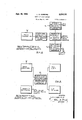
- Figure 1 is a schematic diagram of the ar- 10 rangement of my invention, comprising an ultra high frequency transmitter and receiving as- ,:sembly and diagrammatically showing thepositrol;
- Fig. 2 is a. block diagram showing the arrangement of the transmitter and automatic control circuits;
- Fig. 3 is a block diagram of the arrangement of the receiver and automatic 20 control circuits;
- Fig. 4 is a front elevation of a. public service box; signal light, and pedestal mounting illustrating the antenna arranged thereon;
- Fig. 5 is a side elevation of the public service box, signal light, antenna structure and 25 pedestal mounting shown in Fig. 4;
- the call light responds to impulses from the receiver output.
- the receiver output is automatically transferred to the loud speaker for voice or modulated signal reception.
- Special removable cams or manual key operation may be employed at the headquar ters station transmitter to send out emergency flash groups, riot calls or a particular box number.
- the transmitter disc or cam containing the prearranged contactors for closing the signal modulation circuit may be supplemented by a transmitter disc or cam contactors arranged to effect the transmission 'of riot or fire calls and the like.
- a transmitter disc or cam contactors arranged to effect the transmission 'of riot or fire calls and the like.
- This extension of myinvention is possible by adding on the drive shaft of the driving motor a supplemental transmitter disc or cam carrying prearranged signal contactors thereon capable of transmitting the alarm signals.
- These transmitter discs or cams maybe selected by means operative interiorly of the call box when the call box door is opened by a mechanical contrivance to shift a brush member from one transmitting disc or cam to another.
- a number of such transmitter discs or cams may be provided with a brushcontrol member capable of being shifted to any one of the several positions for effecting transmission of a particular group of signals.
- the call box is provided with special forms of control switches, one of which I have designated as the citizens alarm switch S2 operative from .the exterior of the call box and the master control switch S1 operative automatically upon the opening of the call box for conditioning the transmitter, the microphone circuit and the automatic modulation means.
- the citizens alarm switch comprises a suitable tumbler member which may be angularly displaced under control of a control member operative from the exterior of the case to close an electrical contactor against the tension of a spring.
- The;contactor is normally held open by spring tension but upon angular displacement of the tumbler by operation of the control member from the exterior of the case the contactor constituting the citizens alarm switch S2 is closed, energizing the transmitter circult and starting the automatic modulation system.
- Reference character 20 designates the public service or police or fire box having a door 2
- the transmitting apparatus includes a synchronous motor 23 which controls through a contact system'an audio frequency driven by the shaft 21 ofmotor 23.
- the cams are made of metal such as brass and carry a plurality of insulated insets 28 at their outer periphery.
- a spring contactor 29 is slidably and adjustably mounted axially of the motor shaft and selectively engageable with a selected one of the cams 24, 25, and 26.
- the transmitter system includes a voice modulation circuit comprising transformer 33, microphone 34, and a source of potential such as rectifier 35, and the audio frequency modulator 44 is connectiblein shuntwith the microphone 34.
- the transformer 33 has the secondary winding thereof connected with the input of modulator tube I00.
- the output of the modulator tube I00 includes transformer IOI which connects to the power amplifier system I02 for controlling the transmission of high frequency signaling energy from the radiation circuit I033.
- the transmission circuit is energized from the high frequency oscillator circuit constituted at tube I04.
- the oscillator circuit is controlled by constant frequency by means of electric mechanical vibrator or piezo-electric crystal I05.
- the power supply circuits are energized from transformer I06 having a primary winding I01 connected with the power supply system for a plurality of secondary windings indicated at I08, I09, H0.
- Secondary winding I08 supplies plate potential for the full wave rectifier III.
- Secondary winding I09 supplies cathode heating po- If, for example, the citizens-alarm I tential for the full wave rectifier ill.
- Secondary winding I I supplies cathode heating po-.
- the full wave rectifier! ll delivers rectified current to. the filter circuit H2 across which potentiometer H4 is connected and from which suitable potentials are supplied for the plate 'circuit of the several tubes of the transmitter.
- the switch S2 comprises a shaft 38 extending outwardly through the opening 39 disposed in the door 2i.
- receiving circuit comprises a connection to the antenna system which may be the reflector 81 shown more particularly in Figs. 4, and 6 connected through series condenser H5 to inductance H6 which connects to the tuned input circuit of amplifier Ill.
- the amplifier H'l de- H9 through suitable transformer I20.
- the output of detector circuit H9 connects-through audio frequency transformer I2! to the input of the first stage of audio frequency amplification designated at I22.
- v,A second stage of audio frequency amplification may be employed as indicated at I23.
- cable I28 is well insulated from the structure of the pedestal mounting and that a detachable coupling similar to the coupling 89, 83, heretofore described, may be employed in establishing connection with the equipment within box 29.
- the coupling indicated generally as pin and socket connections 89 and 83 are well insulated from the structure of pedestal support and maintain a high degree of electrical efiiciency, allowing the use of reflector 81 as a receiving antenna if desired independently of its use in coaction with the directive antenna '84 during transmission. Because of 'the wide range of adjustability of the antenna.
- the numeral 90 designates gen erally the location of battery housings for lowthat it does not respond to the emitted frequency of the transmitting'circuit lll3-l 18 connected to antenna I4.
- supplies current to the grids lg of the main oscillator circuit.
- the ballast resistor 92 and bias resistor 93 are connected in series to the heater type cathode la and to a midpoint in inductance coil 9
- the plates Ip of the oscillator tube have a pair of parallel busses 94 and 95 connected therewith. The busses are spaced approximately 1 to 2 inches apart for best results. Transversely across the ends of the busses 94 and 95, I provide an adjustable short-circuiting bar 96 to which radio frequency choke 91 is connected.
- a call box comprising a casing having a hinged cover member
- radio transmitting apparatus and receiving apparatus including a sound reproducer mounted within said casing and having control means operatively connected with said cover member, said radio receiving apparatus being maintained normally in energized condition and having signal means cooperative therewith, and said transmitting apparatus being maintained normally in deenergized condition, with said cover member in closed position, said control means being operated upon the opening of said hinged cover member for conditioning said transmitting apparatus for the transmission of signaling energy and said sound reproducer for the translation of signaling energy received by said receiving apparatus.
- a radio call box system comprising a casing, a cover memberadapted to be opened and closed with respect to said casing, radio transmitting apparatus arranged within said casing, said radio transmitting apparatus including a modulation circuit and a keying circuit, means operative exteriorly of said casing when said cover member is closed with respect thereto for conditioning said radio transmitting apparatus and operating said keying circuit, and means controlled by the opening of said cover member with respect to said casing for simultaneously conditioning said radio transmitting apparatus and rendering both said keying circuit and said modultation circuit operative with respect to said radio transmitting apparatus.
Landscapes
- Engineering & Computer Science (AREA)
- Computer Networks & Wireless Communication (AREA)
- Business, Economics & Management (AREA)
- Emergency Management (AREA)
- Physics & Mathematics (AREA)
- General Physics & Mathematics (AREA)
- Signal Processing (AREA)
- Transmitters (AREA)
Description
Sept. 1940- L. G. CUMMINGx 2,214,101
RADIO CALL BOX SYSTEM Filed May 27, 1938 5 Sheets-Sheet 1 UN IT swan (Ac) R. L.G .CUMMING Sept. 10, 1940.
RADIO cam. BOX SYSTEM L. G. CUMMING Filed May 27, 1938 5 Sheets-Sheet 2 RADIO AUTOMATIC oo- ULATION SYSTEM.
TRANSM ITTER POWER SUPPLY POWE Q TRANSMITTER IDENTIFIES STATION WHEN TRANSMITTER OR BATT E RY gzgg IS usso. PERATED' TRANSMITTER.
ALARM VSWITCH oPEmrEs EXTERNALLY RADIO TRANSM ITTER AN D REss-r MANUALLY.
AUTOMATIC CONTROL CIRCUITS.
RADIO RECEIVER LIGHTONLYOPERATES D00 R OPEN -LOUD SPEAKER A LSO OPERATES RECEIVER POWER 5U PPLY RADIO RECEIVER AND TO AC. D.C.-OR
BATTERY POWER SOURC E.
AUTOMATIC CONTROL CIRCUITS D055 NOT CONTROL MICROPHONE TRIPFING DEVIC E,
CALL. LIGHT LOUD SPEAK ER INVENYTQR. L. G. C UMM I N G ATTORNEY p 1940- 1.. s. CUMMING 2,214,101
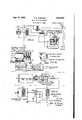
RADIO CALL BOX SYSTEM V Filed May 27, 1938 5 Sheets-Sheet 3 CALL LIGHT CALL LIGHT INVENTOR. .e CUMMING ATTORNEY I 1E0, 1940- G. CUMMING 2,214,101
RADIEO BOX SYSTEM Filed May 27, 1938 5 Sheets-Sheet 4 49 s EcTloN '7-7 Sz M I DOOR CLOSED fl -l 000R OPEN 39 Flas- Z0 TRANSMITTER 6 RECEIVER 6 PANEL ARRANGEMENT FIG. 9
AUTOMATIC SIGNAL SELECTOR AND CO NTRO L.
E INVENTOR. 16. :0 L.G.CUMM|NG ATTORNEY 1.. e. CUMMING: 2,214,101 RADIO CALL Box SYSTEM Filed May 27, 1 938 5 Sheets-Sheet 5 TOTRANSMITTER Z CQNJLROL $2 1 1271 ac: MOTOR REDUCTION T GEAR" OR lls VOLT o MICROPHONE POWER IRRM. G0 CYCLE SYNCH RO NOUS MOTOR 15 27 INSQJLATED INSETS coo ED CAM Ill Y I 29 SPRING CQNTACTO WER SUPP TO MOTOR $TRANsw-TTER loo H6. '8
V poo vcL E 1 MIC o R PHONE AND BUZZERQR To MODULATOR BUZZER POWER SUPPLY E IVALENT INPU HGJZ m TOANT'ENNA Slfi H 96 F'OR EXTREMELY HIGH FREQUENCIES lol FIG I O LATOR MICROPHONE POWER INVENTOR- SUPPLY L.G. CUMM|NG v ATTORNEY 2,214,101 name can. BOX SYSTEM "Laurence G. Cumming, Boston, Mass, assignor of Ione-half to Edmund 0. Mayo, Providence, R.
Application May 27, 1938, Serial No. 210,475
' 12 Claims. c ean-s), V
a plurality of public service boxes and a central control station.
- One of the objects of my invention is to supplement existing cable'connected police or fire boxes with relatively inexpensive transmitterreceiver assemblies that are practicable for installation within the appropriations generally available in small municipalities.
Another object of my invention is to provide means ,for permitting a 'citizen or person to readily effect the transmission of a signal to a central station in cases of emergency from a public service box.
Still another object of my invention is to provide an automatic call means for identifying any particular box for effecting the transmission of radio signals from public service boxes to a central station.
- A further object of my invention is to provide a radio transmission system for public service boxes that is initiated in operation when the housing door of the .public service box is opened, and which will be automatically deenergized when the housing door is closed.
A still further objectof my invention is to provide a construction of public service box 80 having means for automatically .rendering operative a radio transmitter and simultaneously and selectively actuating an automatic periodic identifying call or modulating system and raditransmitting radio signals to a central station.
with minimum mutual interference.
vA further object of my'invention to pro-- 50 videan arrangement of signal receiving system for public seryice'boxes in which a signal light "-is energized adjacent the box when a radio signal isincident upon the box: for attracting the attention'of apatrolman who may then open the qd-Ibox thus automatically placing in operation a loud speaker sound reproducer for delivering the message being transmitted.
Other objects and advantages of my invention will be apparent during the course of the following specification. 5
In. the accompanying drawings, forming a part of this specification, and in which like numerals are employed to designate like parts throughout the several views:
Figure 1 is a schematic diagram of the ar- 10 rangement of my invention, comprising an ultra high frequency transmitter and receiving as- ,:sembly and diagrammatically showing thepositrol; Fig. 2 is a. block diagram showing the arrangement of the transmitter and automatic control circuits; Fig. 3 isa block diagram of the arrangement of the receiver and automatic 20 control circuits; Fig. 4 is a front elevation of a. public service box; signal light, and pedestal mounting illustrating the antenna arranged thereon; Fig. 5 is a side elevation of the public service box, signal light, antenna structure and 25 pedestal mounting shown in Fig. 4; Fig. 6 is a fragmentary front elevation, shown partially in section of the'ultra high frequency directional antenna-reflector and call-light unit used in combination with the public service box; Fig. 7 is a transverse horizontal section taken on.- the line 1| of Fig. 9, but showing the door of the public service box closed and illustrating the corresponding position of the master control-- switch that conditions the transmitter; Fig. 8
is a transverse horizontal 'section taken on line l'! of Fig. 9, but showing the door of the public service .box open and the master control switch in a position to render the transmitter "operative by voice modulation; Fig. 9 is a front 0 elevation of the public service box showing the door open, and illustrating the panel arrange- .ment of the radio transmitter and receiver:
Fig. 10 is a transverse horizontal section through the public service box taken on the line NI -Ill of Fig. 9; Fig. 11 is a schematic diagram in somewhat larger form of the arrangement-of the automatic call-light circuit, citizens switch and master switch for the public service box; Fig l z is a side elevation of the synchronous motor and coded cam arrangement and selective connecting means employed for controlling the, modulating circuits of the transmitter of my invention; Fig. 13 is a front elevationof the coded cam andselective spring contactor arinvention.
While I have disclosed preferred embodiments of my invention in the specification hereinafter following it will be understood that various modifications are contemplated within the scope of my invention, and I do not intend that my invention shall be limited to the particular form shown.
My invention is directed to a public service system for municipalities employing radio as a means of communication, to supplement existing cable connected public service boxes. My system also eliminates the necessity of metallic circuits between public service boxes and division stations, or other radio headquartersthereby greatly decreasing installation costs and facilitating installation of public service systems in municipalities. The system of my invention supplies a definite need in present day police, fire and public service communications.
The system of my invention enables the installation of the Radio-Box which is a term I- have coined in lieu of the heretofore existing public service box, to be made with but few changes in existing systems. The Radio-Box is designed to replace and supplement the various In remotely located boxes which do not usually incorporate the ;call light it is not necessary to install the aforementioned combination light and antenna mounting. Remote boxes are usually devoid of any commercial power supply, and
in such cases it will be necessary to construct a Weather and tamper proof storage battery housing near the Radio-Box.
The entire transmitter-receiver assembly is designed to be removed from the box as a unit. The radio assembly is secured in the housing by six or more wings, or knurled studs to facilitate quick replacement when service is necessary.
Every effort has been made to standardize both radio components, and complete assembly sizes. This assures the lowest possible maintenance cost and renders the system conversion cost, from wire to radio, so low that it is within reach of the small municipalities. This principle of low cost procurement materially assists the smaller communities, which are unable to have the necessary number of police or fire box installations, due to the prohibitive cost of equipment and lines', and budgetary limitations.
The antenna system consists of a one-quarter wave vertical antenna. A parasitic reflector spaced on the same adjustable mounting which carries the antenna is located one-eighth to three-eighths wave lengths behind the antenna. The antenna and reflector assembly is adjustable for directional characteristics and may be locked in position when adjusted, by a collar and set screw device on the box housing.
An indispensable function of modern police, fire. or public service communication is that the radio channel or system, may be made available for citizen emergency use. I provide a Qitizens Alarm as part of the regular police box equipment in the Radio-Box." For this purpose a glass covered trip switch, or the equivalent, capable 'of being reset, is included as part of the Radio-Box equipment. This switch is connected in multiple across the transmitter master control spring switch and employed by the citizenry for emergency use only. The tripping of this switch puts the transmitter on the air, and automatically broadcasts the box number once or more a minute. It does not open the voice channel to the citizen, as the housing box door is still closed. The reception of a-series of box number calls at the division station, when no answer can be obtained from the box, will constitute an alarm sufficient immediately to dispatch cars to the scene.
An electric induction motor or equivalent type of synchronous clock motor, is employedto operate a cam device having the police, fire box or other identification. This cam, revolving at one revolution per minute actuates a contactor, which in turn operates an audio frequency tone modulation system. An inverse feedback arrangement, or a buzzer, in the modulator tube grid circuit, is employed as the source of modulation. This modulating circuit is controlled by the revolving cam, which automatically broadcasts the box number once or more every minute, while the transmitter is in use. By this means it is possible to record each box number at the receiving point, or precinct station-house.
It is considered that the application of this automatic call identification system, (the synchronous clock operated cam) fills a definite need in police, fire or similar types of radio services in use at present.
Near the left edge of the transmitter panel is mounted a master control, door type spring switch. The purpose of this switch is to automatically turn off the transmitter when the outside door of the box mounting is closed. When the latter door is opened, this spring switch closes and turns on the power supply to the transmitter. Thus the transmitter is in operation .only when the housing door is opened, and is automatically turned off, when the door is closed, unless turned on by the use of the "Citizen's Alarm switch, when it must be reset by the officer or service department.
As several low powered ultra high frequency transmitters will be operating on the same or contiguous frequencies, it is considered necessary to employ a crystal controlled oscillator circuit. At the present stage of development of the radio art it is not practical to employ crystals having a fundamental frequency in excess of 15 megacycles. Crystals of this frequency produce sufilcient power and stability to permit satisfactory doubling, or quadrupling to the desired frequency in two, or at the most, three tubes. The antenna-refiector type of directive radiation system employed is depended upon to reduce interference on the same or contiguous frequencies.
As the receiver functions twenty-four hours a day, semi-automatic operation is obtained. An important part of modern police work is the quick response obtained through the modern communication systems. One of the most effective developments for calling is the red call light" pro- ,vided in the Radio-Box. It is necessary to employ a single pole single throw relay, or the equivalent, operating from the receiver output. The
When the box housing door is opened, a switch aerator from the call light" relay control circuit to a loud speaker, which is an integral part ,of the receiver. When the box housing door is'closed,
the call light responds to impulses from the receiver output. When this door is open, the receiver output is automatically transferred to the loud speaker for voice or modulated signal reception. Special removable cams or manual key operation may be employed at the headquar ters station transmitter to send out emergency flash groups, riot calls or a particular box number.
These flash groups, box numbers or code signals are received by the Radio-Box as either light flashes, when the Radio-Box is not in use,
before the oflicer arrives, or as modulated code signals when the receiver loud speaker is in use. This automatic interchangeable use of the radio receiver to operate either the light flashing relay or the loud speaker insures secrecy when the Radio-Box is not in actual use, as the loud speaker is cut out of circuit, and does not respond to 'voice reception until the door is opened by an authorized person.
The"Radio-Box design permits the employment of frequencies recently assigned to General Experimental, Police, Fire and Forestry Services by the Federal Communications Commission. Among those frequencies are the ones chosen for the initial tests and are between ap proximately 128 megacycles and 141 megacycles.
The transmitting and receiving apparatus is compactly assembled within a standard type of a public service call box such as a fire ,or police box adapted to be mounted on the usual pedest support on the sidewalk or building structure or in any other box such as on board a train or fire truck, or police or fire boat. The transmitter and receiver have the circuits thereof powered from the available source of alternating current power supply or battery. nWhile the transmitting range of the transmitter is not critical, I .have successfully communicated distances of five miles or more using the circuits of my invention at ground levels. At elevated positions, the transmitting range of the equipment is substantially greater. The transmitter includes a high frequency oscillator and frequency multiby prearranged audio frequency signals, or at successive repeating time intervals a combination of voice controlled andprearranged signals may be employed.
The prearranged audio frequency modulation is effected by means of a motor controlled audio frequency oscillator. The audio frequency oscillator is rendered'efiective on the modulation circuit of'the transmitter in accordance with prearranged code signals under control of a suitably calibrated discor cam devicedriven by the motor. In direct current installations; the driving motor may be a simple series wound direct current motorassociated with .a suitable reduction gear operating the code transmitting device.)
When alternating current is available, a syn'-,' .chronous motor is used for driving the transidentification of the transmitting station and does not offer serious interference with the voice modulation as the voice modulation is intelligible through the spaced successive interruptions offered by the code signals. This call when received more than five or six times without an accompanying voice modulated signal, automatically constitutes an alarm at the central station.
This immediately dispatches mobile or portable units to the scene of the original box to determine the reason for the lack of voice communication, or response.
The transmitter disc or cam containing the prearranged contactors for closing the signal modulation circuit may be supplemented by a transmitter disc or cam contactors arranged to effect the transmission 'of riot or fire calls and the like. This extension of myinvention is possible by adding on the drive shaft of the driving motor a supplemental transmitter disc or cam carrying prearranged signal contactors thereon capable of transmitting the alarm signals. These transmitter discs or cams maybe selected by means operative interiorly of the call box when the call box door is opened by a mechanical contrivance to shift a brush member from one transmitting disc or cam to another. A number of such transmitter discs or cams may be provided with a brushcontrol member capable of being shifted to any one of the several positions for effecting transmission of a particular group of signals.
As heretofore noted,'the transmitting and receiving apparatus is compactly assembled within the call box and the warning light mounted above the call box on a suitable support adapted to carry the transmitting and receiving antenna.
In order to render the equipment" universal in antenna structure is capable of being angularly adjusted in position on the support above the call box. Moreover, the antenna structure is equipped with an emitting portion and a reflecting portion capable of adjustable spacial relation one with respect to the other. Because of the many "'diiferences in directional characteristics encounteredin installations embodying my invention, the antenna structure must be capable antenna structure in different angular positions with respect to thevertical as wellas various positions with respect to the transverse spacial relation 'of the emitting portion with-respect to the reflecting portion. Such changes in angular position are particularly valuable where obstructions to the radiation of high frequency energy may occur. The antenna reflector type of radiation system which I employ is depended upon to reduce interference on the same or contiguous frequencies when a. plurality of stations are used.
The adjustable arrangement of the antenna structure of my invention is advantageous in arranging the antennas" on different call boxes in.
variousdirections to coactwith a central stationwithout mutual interference. One call'box' staI-J tion has negligible effect upon another call box station for the antenna arrangement at each call box station is so devised as to emit the high frequency energy in that plane of polarization which will be received at the central station irrespective of energy being simultaneously emitted from other call box stations in the area about the central station. The antenna structure herein disclosed is the subject matter of a divisional application, Serial No. 274,255, filed May 17, 1939, for Antenna system.
I am not unmindful of the problems which arise in multiple systems of transmission wherein a number of permutations and combinations of transmissions may occur at the same 'frequency for signals transmitted to the same central station, whether the system be for purposes of fire, police, general communication, traific control, marine, aviation or mobile systems generally. However, the central station may be readily equipped with directional receiving means capable of discriminating against signals in certain areas while allowing reinforced reception of signals in other areas and consequent increase.
in signal to noise ratio. Moreover, I contemplate in my system the employment of sequence transmission in cases of emergencyso that an authorized agent at any one of the callboxes may be informed from a central station to stand.
by pending the clearance of an emergency call or priority message from some other call box station.
The receiving apparatus employed within the call box is continuously energized and maintained in operative condition prepared for the; reception of signals. A relay operated from the output circuit of the last stage of power amplifica-.
tion is functioned so long as a modulated signal is received by the receiving apparatus to'close a power supply circuit to an indicator light visible from the exterior of the call box. This provides a signal for attracting the attention of a patrolman to the call box whereby the patrolman will be informed of the fact that a modulated signal is being received and will utilize the receiver at the call box for audibly receiving the signal. While the receiving apparatus is maintained in operative condition at all times, the loud speaker winding is normally shunted for preventing reproduction of sound when the call box is closed.
The call box is provided with special forms of control switches, one of which I have designated as the citizens alarm switch S2 operative from .the exterior of the call box and the master control switch S1 operative automatically upon the opening of the call box for conditioning the transmitter, the microphone circuit and the automatic modulation means. The citizens alarm switch comprises a suitable tumbler member which may be angularly displaced under control of a control member operative from the exterior of the case to close an electrical contactor against the tension of a spring. The;contactor is normally held open by spring tension but upon angular displacement of the tumbler by operation of the control member from the exterior of the case the contactor constituting the citizens alarm switch S2 is closed, energizing the transmitter circult and starting the automatic modulation system. The fact that the call box has been operated immediately results in the automatic 'transmission of repeat signals identifying the particular call box. This signal capable of being received bythe central station (or by cruising police cars and other stations) immediately informs the cenrying a key to the call box is enabled to open the call box and in doing so, the spring actuated master control switch S1 is automatically operated, closing the microphone circuit, insuring the completion of the voice input circuit to the transmitter and disconnecting the shunt path to the loud speaker winding of the receiver. It will be noted that the citizens alarm switch S2 is connected in parallel with the power circuit contacts of the master control switch S1 so that the transmitter may be conditioned for operation either from the exterior of the 'call box by operation of switch S2 or automatically conditioned upon opening of the call box by operation of switch S1. switch S2 has not been actuated from the exterior of the call box, the transmitter is placed in operative condition upon opening the door of the call box.
The transmitter system includes a voice modulation circuit comprising transformer 33, microphone 34, and a source of potential such as rectifier 35, and the audio frequency modulator 44 is connectiblein shuntwith the microphone 34. The transformer 33 has the secondary winding thereof connected with the input of modulator tube I00. The output of the modulator tube I00 includes transformer IOI which connects to the power amplifier system I02 for controlling the transmission of high frequency signaling energy from the radiation circuit I033. The transmission circuit is energized from the high frequency oscillator circuit constituted at tube I04. The oscillator circuit is controlled by constant frequency by means of electric mechanical vibrator or piezo-electric crystal I05. The power supply circuits are energized from transformer I06 having a primary winding I01 connected with the power supply system for a plurality of secondary windings indicated at I08, I09, H0. Secondary winding I08 supplies plate potential for the full wave rectifier III. Secondary winding I09 supplies cathode heating po- If, for example, the citizens-alarm I tential for the full wave rectifier ill. Secondary winding I I supplies cathode heating po-.
tential for all of the tubes of the transmitter. The full wave rectifier! ll delivers rectified current to. the filter circuit H2 across which potentiometer H4 is connected and from which suitable potentials are supplied for the plate 'circuit of the several tubes of the transmitter.
Operable from without the box 20 is the citizens control switch indicated at $2. The switch S2 comprises a shaft 38 extending outwardly through the opening 39 disposed in the door 2i.
' A handle 40 is arranged on the outer end of livers energy to the regenerative detector circuit the shaft 38. The inner end of the shaft 38 projects through'the panel 30 and carries a cam 4!. Cam 4| serves to actuate a contactor 42 against the tension of spring 43. The action of turning the handle 40, closes the contactor 42 and automatically energizes the transmitter, and automatically starts the motor .23, thereby operating the transmitterfor radiating a series of code signals under control of the coded .cam 26.
The operation of the switch S2 does not connect the loud speaker 36 to the receiver circuit and therefore the voice channel is not closed by the a citizen.
The circuits of the receiving system are energized from the same power supply system which supplies energy to the transmission system. The
receiving circuit comprises a connection to the antenna system which may be the reflector 81 shown more particularly in Figs. 4, and 6 connected through series condenser H5 to inductance H6 which connects to the tuned input circuit of amplifier Ill. The amplifier H'l de- H9 through suitable transformer I20. The output of detector circuit H9 connects-through audio frequency transformer I2! to the input of the first stage of audio frequency amplification designated at I22. v,A second stage of audio frequency amplification may be employed as indicated at I23. The output circuit of the second stage of audio frequency amplification connects through output'transformer 124 to the winding I25 of the loud speaker 36 so that the winding I25 is normally energized continuously by the receiving system exceptthat it is rendered ineffective by reasonof the shunt circuit effected 'by'contacts 54 and 55 of the master control door switch'sl. The output circuit of the last stage of met or bushing 48 through which tubular member 57 is adapted to .move. The numeral designates a resilient plug adapted to fit into and project slightly beyond the outer end of the tubular member 21 and engageable by the door 2! of the box. Pin member 50 is fixed at its rear end 5| to the back of the box 20 and extends into the hollow tubular member 41. Insulated plate member 52 is carried by pin member 50 and serves to'support contacts on both the rear-and front thereof as shown. A spring 53 is interposed between plate member 52 and the back ofv the box 20. The plug 49 ordinarily projects slightly beyond the inner surface of the door 2 I, so that when the door is closed the tubular member 41 and consequently the plate 52 is rearwardly displaced against the tension of the spring 53. This action closes a pair of contacts 54 and 55. The contact 54 is carried by the plate member 52 and the contact 55 is insulatingly supported from the rear of the box 20. Contacts 54 and 55 are connected in parallel with the winding of loud speaker 36 and consequently maintains the same shunted and inoperative when the door 2| is closed. The numbers 58 and 51 designate dual contacts arranged between the frame 46 and the plate member 52. When the door 2| is closed and the plate member 52 retracted against the tension of spring 50 the dual contacts 56'and 51 are broken. The contact 51 and the coacting contact carried by plate mem ber 52 are connected in shunt with the citizens switch S2. The contact 55 and its associated contact on plate member 52 are connected in series with the voice modulation circuit containing the primary'winding of transformer 33. When the door 2| is opened the contacts 55 and 51 and their coacting contacts on plate member 52 are closed by the action of the spring 53 closing the microphone circuit and insuring the completion of the voice input circuitto the transmitter. The contact 54 and its coacting contact 55 are broken, disconnecting the shunt path to the loud speaker The numeral 58 designates the position of the microphone in the transmitting panel. The microphone is surrounded and protected by a suitable guard 59.
The numeral 50 designates the loud speaker opening in the receiving panel, said opening being protected acoustically from the microphone by the semi-circular guard M. The purposes of the guards 59 and 5! are twofold, to protect the instrumentalities from the weather, and to reducetendency of feedback from the loud speaker Firmly connected to the clamp 65, I provide a I tubular antenna arm 57 forming a frame for mounting the antenna structure. The screw 66 permits the entire frame carrying the tubular antenna arm to be selectively adjusted in position. The endsof the arm 67 are provided with taper threads 68 and slots therein, permitting the nuts 10 to grip' very tightly for securing the extension'members H and 85 in selected posi tions. 7 The extension member H has its one end I2 fitting into arm 6! and its other end 13 bent at substantially right angles with respect to the end 12. Projecting upwardly from the end 13 of the extension H and protected therefrom by insulating grommet or bushing 115 there is a transmitting antenna M. The grommet or bushing 75 serves as an insulated support forthe antenna 15. The antenna 84 is held firmly in place by virtue of pressure exerted uponrthe mounting means '85 by the screw i6 through the grommet or bushing i5.
' The numeral 11 designates a conduit having" its outer end I8 fitting into the end I2 of the tubular. extension H. The conduit ll passes through but is spaced away from the inner walls of arm 61 and emerges from the arm through opening 19 and projects downwardly through the prism 63. An electrical connection 8| passes through conduit 11 and tubular extension 11 and connects with antenna 14 as shown. Arranged on the downwardly projecting end of the tube I1, I provide a plug member with connecting stud 82 projecting therefrom. A detachable connection is provided for interconnecting plug sion ll. Extension tube 85 is provided at its extremity with an upwardly extending end 86 carrying a parasitic or power fed reflector 81, said reflector being separated from said extension tube- 85 by means of insulating grommet or bushing 88. The insulating grommet or bushing 88 is held firmly in place by means of pressure exerted by set screw 89 upon grommet 88. The reflector is shown at 81 in parallel alignment with the antenna 14. The reflector 81 is connected through a cable 428 which may extend in a conduit similar to conduit 17 through arm 61 and through the call light housing to the equipment within the call box 20. For purposes of explaining my invention, I have merely indicated the connecting cable I28 in Fig. 6. It will be understood that cable I28 is well insulated from the structure of the pedestal mounting and that a detachable coupling similar to the coupling 89, 83, heretofore described, may be employed in establishing connection with the equipment within box 29. It will be understood that the coupling indicated generally as pin and socket connections 89 and 83 are well insulated from the structure of pedestal support and maintain a high degree of electrical efiiciency, allowing the use of reflector 81 as a receiving antenna if desired independently of its use in coaction with the directive antenna '84 during transmission. Because of 'the wide range of adjustability of the antenna. 14 and reflector 81 and the adjustability provided by angularly shiftable support 65 with respect to the pedestal mountin a high degree of precision in the directive transmission and receiving characteristics of the antenna and'reflector system is insured. This makes it possible to adjust and set each of the antenna-reflector combinations on each of the public service boxes with respect to the central station with which the public service box coacts; The numeral 90 designates gen erally the location of battery housings for lowthat it does not respond to the emitted frequency of the transmitting'circuit lll3-l 18 connected to antenna I4.
Another form of my invention which I find ex-. tremely satisfactory on frequencies above. 100
megacycles is shown in Fig. 14. In this feedback oscillator type of circuit inductance coil 9| supplies current to the grids lg of the main oscillator circuit. The ballast resistor 92 and bias resistor 93 are connected in series to the heater type cathode la and to a midpoint in inductance coil 9| which completes the oscillator circuit. The plates Ip of the oscillator tube have a pair of parallel busses 94 and 95 connected therewith. The busses are spaced approximately 1 to 2 inches apart for best results. Transversely across the ends of the busses 94 and 95, I provide an adjustable short-circuiting bar 96 to which radio frequency choke 91 is connected. The modulation circuit for the modified form of my invention illustrated in'Fig. 14 is similar to the modulation circuit employed in the system illustrated in Fig. 1. That is, microphone 34 connects through microphone transformer 33 to the input of the modulated tube I99, the output of which connects through transformer I0l to the control circuit of the high frequency oscillator system.
The Radio-Box design permits the employment of frequencies assigned to General Experimental, Police, Fire, Forestry and Other Public Services by the Federal Communications Commission. Among these frequencies were the ones chosen for the initial tests between one hundred and twenty-eight and one hundred and forty- 1. Fire signal boxes.
2. Police signal boxes.
3. Mobile fire and police equipment, including boats, trucks, aircraft, trailers, etc.
4. Municipal, state and federal forestry fire I have described my invention in certain of its preferred embodiments but I fully realize that modifications may be made and no limitations upon my invention are intended other than may be imposed by the scope of the appended claims. I
What I claim as new and desire to secure by Letters Patent of the United States is as follows:
1. In a radio call box system, in combination. a box having a cover and locking means therefor, radio transmitting and receiving means within said box including a modulating system having an automatic keying circuit and a voice modulation circuit, said receiving means including a sound reproducer and signal light means, said light means being visible exteriorly of said box; switching means manually controllable 75 from the exterior of said box for rendering said automatic keying circuit effective in the modulating system, and a cover actuated switch having a set of contacts operative with the cover closed .for maintaining said sound reproducer inoperative and said signal light means operative; said cover actuated switch having dual sets of contacts operative with the cover open, one set of said contacts being connected in shunt with the aforesaid switching means, and the other set of said contacts being connected insaid voice modulation circuit.
2. In a radio call box system, in combination, a box having a cover, radio transmitting and receiving means within said box, said transmitting means including a modulating system having an automatic keying circuitand a voice modulation circuit, said receiving means including a sound reproducer and signal light means, said light means being visible exteriorly of said box, means operative with said box closed for maintaining said modulating system and said sound reproducer inoperative, and switching means operable from the exterior of said box for operating said keying circuit in the modulating system independently of the last said means.
3. In a radio call box system, a call box comprising a casing having a hinged cover member,
radio transmitting apparatus and receiving apparatus including a sound reproducer mounted within said casing and having control means operatively connected with said cover member, said radio receiving apparatus being maintained normally in energized condition and having signal means cooperative therewith, and said transmitting apparatus being maintained normally in deenergized condition, with said cover member in closed position, said control means being operated upon the opening of said hinged cover member for conditioning said transmitting apparatus for the transmission of signaling energy and said sound reproducer for the translation of signaling energy received by said receiving apparatus.
4. A radio call box system comprising in com bination, a call box including a casing having a cover member hinged with respect thereto, radio transmitting and receiving apparatus mounted within said call box, the transmitting apparatus including a voice modulation circuit and a telegraphic control circuit, said receiving apparatus including a sound reproducing circuit, means actuated by said hinged cover member when in closed position for renderingsaidmodulation circuit and said sound reproducing apparatus inoperative, said telegraphic control circuit being operable independently of said modulation circuit, and means actuated upon the opening of said hinged cover member with respect to said casin for rendering said sound reproducing apparatus operative and said modulation circuit operative in conjunction with said control circuit for controlling said transmitting apparatus.
5. A radiocall box comprising a call box including a casing and a radio receiving and mounted with said casing,
transmitting apparatus a sound reproducer connected with said radio receiving apparatus,
said radio transmitting apparatus including a modulation circuit and a keying circuit, means within said casing actuated by the closure member when in closed position for maintaining said sound reproducing apparatus and said transmitting apparatus inoperative, means operative exteriorly of said casing when said closure member is in closed position for energizing said transclosure member therefor,-
mitting apparatus and operating said keying circuit, and means operative upon the opening oi! said closure member with respect to said casing for rendering said sound reproducing apparatus operative and said modulation circuit operative for controlling said transmitting apparatus.
6. A call box systein comprising a call box including a casing and a hinged cover member' therefor, a radio transmitter and a radio receiver mounted within said casing, sound reproducing apparatus connected with said radio receiver, means for normally energizing said radio receiver, a modulation circuit and a keying circuit for controlling said radio transmitter, separate circuit controllers, one of said circuit controllers being operative from the exterior of said casing when said cover member is in closed position, and the other of said circuit controllers being operative interiorly of said casing by said cover member in open and closed position, means operated by the last said circuit controller with said cover member in closed position for maintaining said sound reproducing apparatus inoperative, means controlled by the circuit controller which is operative from the exterior of said casing-when said cover member is in closed position for energizing hinged cover' thereof is open for rendering said sound reproducing apparatus operative and said modulation circuit operative in conjunction with I said keying circuit.
7. In a radio call box system, can box including a casing and a cover member movable to either a closed or open position with respect to said casing, signal receiving apparatus mounted within said casing and including a sighalreceiving circuit, a sound reproducer, and a visual signal control circuit within said casing, visual means mounted exteriorly of said casing and controlled by said visual signal control circuit, a circuit controller mounted interiorly of said casing and operative under control of the movement of said cover memberfor rendering said sound'reproducer inoperative when said cover member is closed while maintaining said signal receiving circuit energized and said visual signal control circuit responsive to signaling energy incident upon said signal receiving circuit for actuating said visual signal exteriorly of said casing.
8. In a call box system, a casing, a cover member'for' said casing movable to either an open or closed position with respect thereto, a radio receiver mounted within said casing and including a signal receiving circuit, a sound reproducer, and
a'visual signal responsive circuit within said casing, means for continuously maintaining said signal receiving circuit in operative condition for the reception of signaling energy, means controlled by the position of said cover member when closed for normally maintaining 'said sound reproducer inoperative, and means operative by the opening of said cover member with respect to said casing for restoring said sound reproducer to operative condition with respect to said signal receiving circuit, said visual signal responsive circuit being -maintained operative with respect to said signal lation circuit and an automatic keying circuit,
means controllable exteriorly of said casing when said cover member is closed with respect thereto for conditioning said radio transmitting apparatus and operating said automatic keying circuit, and means controlled by the opening of said cover member with respect to said casing for conditioning' said radio transmitting apparatus and rendering said voice modulation circuit and said keying circuit operative with respect thereto.
10. A radio call box system comprising a casing, a cover memberadapted to be opened and closed with respect to said casing, radio transmitting apparatus arranged within said casing, said radio transmitting apparatus including a modulation circuit and a keying circuit, means operative exteriorly of said casing when said cover member is closed with respect thereto for conditioning said radio transmitting apparatus and operating said keying circuit, and means controlled by the opening of said cover member with respect to said casing for simultaneously conditioning said radio transmitting apparatus and rendering both said keying circuit and said modultation circuit operative with respect to said radio transmitting apparatus.
11. A radio call box system comprising a call box including a casing, a cover member movable to either open or closed position with respect to said casing, radio transmitting apparatus mounted within said casing, a modulation circuit for said radio transmitting apparatus, a keying circuit for said radio transmitting apparatus, code means for actuating said keying circuit, a circuit controller operatively connected with said cover member, said cover member when in closed position operating said circuit controller to maintain said keying circuit inoperative with respect to said radio transmitting apparatus, while maintaining said modulation circuit also inoperative with respect thereto, and said circuit controller being operative upon the opening of said cover with respect to said casing for rendering both said' modulation circuit and said keying circuit operative with respect to said radio transmitting apparatus.
12. A radio call box system comprising a call box including a casing, a cover member movable to either open or closed position with respect to said casing, radio transmitting apparatus mounted within said casing, a modulation circuit for said radio transmitting apparatus, a keying circuit for said radio transmitting apparatus, selective code means for actuating said keying circuit, a circuit controller operatively connected with said cover member, said cover member when in closed position operating said circuit controller to maintain said keying circuit inoperative with respect to said radio transmitting apparatus, while maintaining said modulation circuit also inoperative with respect thereto, and said circuit controller being operative upon the opening of said cover with respect to said casing for rendering both said modulation circuit and said keying circuit operative with respect to said radio transmitting apparatus, and a selector operative when said cover member is in open position with respect to said casing for selectively determining the particular code means by which said keying circuit controls said radio transmitting apparatus.
LAURENCE G. CUMIMING.
Priority Applications (2)
| Application Number | Priority Date | Filing Date | Title |
|---|---|---|---|
| US210475A US2214101A (en) | 1938-05-27 | 1938-05-27 | Radio call box system |
| US274255A US2214102A (en) | 1938-05-27 | 1939-05-17 | Antenna system |
Applications Claiming Priority (1)
| Application Number | Priority Date | Filing Date | Title |
|---|---|---|---|
| US210475A US2214101A (en) | 1938-05-27 | 1938-05-27 | Radio call box system |
Publications (1)
| Publication Number | Publication Date |
|---|---|
| US2214101A true US2214101A (en) | 1940-09-10 |
Family
ID=22783048
Family Applications (1)
| Application Number | Title | Priority Date | Filing Date |
|---|---|---|---|
| US210475A Expired - Lifetime US2214101A (en) | 1938-05-27 | 1938-05-27 | Radio call box system |
Country Status (1)
| Country | Link |
|---|---|
| US (1) | US2214101A (en) |
Cited By (8)
| Publication number | Priority date | Publication date | Assignee | Title |
|---|---|---|---|---|
| US2459105A (en) * | 1941-04-12 | 1949-01-11 | Farnsworth Res Corp | Traffic signaling system |
| US2495452A (en) * | 1946-11-18 | 1950-01-24 | Mobile Comm Company | Communication system |
| US2515561A (en) * | 1948-06-21 | 1950-07-18 | Frank M Lindley | Communication mechanism |
| US2623992A (en) * | 1949-06-28 | 1952-12-30 | Technical Alliance Inc | Radio transmitter control |
| US2623991A (en) * | 1948-05-25 | 1952-12-30 | Technical Alliance Inc | Radio selective alarm system with a central transmitter |
| US2989621A (en) * | 1956-09-20 | 1961-06-20 | Jennings Radio Mfg Corp | Fire alarm system using a plural oscillator radio transmitter |
| US3113270A (en) * | 1959-12-18 | 1963-12-03 | Standard Res Consultants Inc | Paging and alarm system |
| US3800089A (en) * | 1972-02-24 | 1974-03-26 | Itt | Hands-free emergency telephone system |
-
1938
- 1938-05-27 US US210475A patent/US2214101A/en not_active Expired - Lifetime
Cited By (8)
| Publication number | Priority date | Publication date | Assignee | Title |
|---|---|---|---|---|
| US2459105A (en) * | 1941-04-12 | 1949-01-11 | Farnsworth Res Corp | Traffic signaling system |
| US2495452A (en) * | 1946-11-18 | 1950-01-24 | Mobile Comm Company | Communication system |
| US2623991A (en) * | 1948-05-25 | 1952-12-30 | Technical Alliance Inc | Radio selective alarm system with a central transmitter |
| US2515561A (en) * | 1948-06-21 | 1950-07-18 | Frank M Lindley | Communication mechanism |
| US2623992A (en) * | 1949-06-28 | 1952-12-30 | Technical Alliance Inc | Radio transmitter control |
| US2989621A (en) * | 1956-09-20 | 1961-06-20 | Jennings Radio Mfg Corp | Fire alarm system using a plural oscillator radio transmitter |
| US3113270A (en) * | 1959-12-18 | 1963-12-03 | Standard Res Consultants Inc | Paging and alarm system |
| US3800089A (en) * | 1972-02-24 | 1974-03-26 | Itt | Hands-free emergency telephone system |
Similar Documents
| Publication | Publication Date | Title |
|---|---|---|
| US3694579A (en) | Emergency reporting digital communications system | |
| US3668526A (en) | Communication system having means for causing a distress signal | |
| US6414589B1 (en) | Apparatus for remotely controlling auxiliary doorbell chime from doorbell push button | |
| US4296408A (en) | Location transmitting system | |
| US6127925A (en) | Signalling and/or help request system | |
| US3978468A (en) | Intercom call signaling mechanism | |
| US2214101A (en) | Radio call box system | |
| NO832562L (en) | PROCEDURE AND DEVICE FOR RADIO CONNECTIONS. | |
| US2989621A (en) | Fire alarm system using a plural oscillator radio transmitter | |
| US2495452A (en) | Communication system | |
| US2459105A (en) | Traffic signaling system | |
| US3921074A (en) | Safeguard sentry | |
| EP1501059B1 (en) | Remote doorbell chime extender | |
| US2458558A (en) | Radiotelephone equipment | |
| US2014518A (en) | Remote control system | |
| US2459281A (en) | Two-way radio equipment for lifeboat service | |
| US2607887A (en) | Radio telephone system | |
| US2599904A (en) | Multistation selective communication system | |
| US3665310A (en) | Adapter for converting an am radio receiver into a citizens band channel 9 transceiver | |
| US2165062A (en) | Communicating system | |
| US2280420A (en) | Radio telephone system | |
| US2279739A (en) | Combination multichannel radio rf ceiving and signaling system | |
| US2206231A (en) | Communicating system | |
| US2363145A (en) | Telephone electrical circuit control system | |
| US2425495A (en) | Two-way telephone system |