US2204502A - Revolving garment carrier - Google Patents
Revolving garment carrier Download PDFInfo
- Publication number
- US2204502A US2204502A US219736A US21973638A US2204502A US 2204502 A US2204502 A US 2204502A US 219736 A US219736 A US 219736A US 21973638 A US21973638 A US 21973638A US 2204502 A US2204502 A US 2204502A
- Authority
- US
- United States
- Prior art keywords
- carrier
- shaft
- cam
- base frame
- base
- Prior art date
- Legal status (The legal status is an assumption and is not a legal conclusion. Google has not performed a legal analysis and makes no representation as to the accuracy of the status listed.)
- Expired - Lifetime
Links
- 230000007246 mechanism Effects 0.000 description 6
- 235000000396 iron Nutrition 0.000 description 3
- 238000010276 construction Methods 0.000 description 2
- 238000007689 inspection Methods 0.000 description 2
- 102100027069 Odontogenic ameloblast-associated protein Human genes 0.000 description 1
- 101710091533 Odontogenic ameloblast-associated protein Proteins 0.000 description 1
- 230000009471 action Effects 0.000 description 1
- 239000000969 carrier Substances 0.000 description 1
- 210000005069 ears Anatomy 0.000 description 1
- 230000000694 effects Effects 0.000 description 1
- 238000004519 manufacturing process Methods 0.000 description 1
- 239000002184 metal Substances 0.000 description 1
- 229910001092 metal group alloy Inorganic materials 0.000 description 1
- 238000007747 plating Methods 0.000 description 1
- 230000003014 reinforcing effect Effects 0.000 description 1
- 230000000284 resting effect Effects 0.000 description 1
- 230000008093 supporting effect Effects 0.000 description 1
Images

Classifications
-
- A—HUMAN NECESSITIES
- A47—FURNITURE; DOMESTIC ARTICLES OR APPLIANCES; COFFEE MILLS; SPICE MILLS; SUCTION CLEANERS IN GENERAL
- A47F—SPECIAL FURNITURE, FITTINGS, OR ACCESSORIES FOR SHOPS, STOREHOUSES, BARS, RESTAURANTS OR THE LIKE; PAYING COUNTERS
- A47F7/00—Show stands, hangers, or shelves, adapted for particular articles or materials
- A47F7/19—Show stands, hangers, or shelves, adapted for particular articles or materials for garments
- A47F7/24—Clothes racks
- A47F7/26—Clothes racks extensible from a showcase
Definitions
- This invention relates to improvements in revolving garment carriers.
- the revolving garment carrier of the present invention is intended for use in a display cabinet 5 or closet, or other limited area for the purpose of providing increased garment carrying means,
- a garment cara rier having a rotatable shaft which carries a pair of parallel, spaced garment hanging rods.
- the garment carrier is mounted on rollers to permit movement to a position wholly within the cabinet or closet, or to a position at the front end or entrance of the cabinet or closet.
- Means are provided to lock the shaft and associated hanging rods to prevent rotation thereof when the carrier is wholly within the cabinet or closet and 20 to unlock the shaft and associated hanging rods when the carrier is at the entrance of the cabinet or closet and therebypermit a reversal of the carrier to enable the ready inspection and removal of the garments from the carrier by a .6 person outside the cabinet or closet.
- the rotatable-garment carrier embodying the 0 present invention is simple in design, construction and assembly and .relatively inexpensive to manufacture.
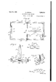
- Figure 1 is a perspective view of a revolving garment carrier embodying my invention
- Figure 2 is a vertical sectional view longitudinally through the carrier base and base frame of the garment carrier of Figure l and showing the carrier base in the rear position on the base 0 frame with the shaft in locked position;
- Figure 3 is a sectional view similar to Figure 2 with the carrier base in the forward position on the base frame and showing the shaft in unlocked position;
- Figure 4 is a horizontal sectional View of the carrier base and base frame on the line 4-4 of Figure 2 showing the base frame in plan;
- Figure 5 is a transverse sectional view on the line 5 5 of Figure 2 showing the details of constructicn of the base frame and the associated locking means for the carrier base;v
- Figure 6 is a fragmentary detail sectional view one line 6-6 of Figure 4, showing the construction of the locking means for the carrier base;
- Figure '7 is a fragmentary perspective view of self-centering mechanism for the shaft.
- the garment carrier comprises a base frame, designated as a whole by the numeral Ill, which is adapted to be positioned in and rest on or be secured to the floor of a display cabinet or closet (not shown) or in any other confined area.
- tlalrier base ll of the garment carrier is supported on flanged rollers l2 which are adapted to run in tracks formed, as hereinafter described, in the base frame.
- Rotatable shaft 53 extends through the carrierbase !i and has secured to the upper end thereof a hanging rack Hi adapted to be rotated therewith.
- a pair of spaced garment hanging rods i5 is secured to rack l4, and end garment guards it are secured to and extend between the garment hang-1 ing rods.
- the base frame II] is of rectangular shape and is formed of a pair of opposed channel irons I1 and 18 which form the sides of the base frame, and end plates l9 and 20.
- the bottom sides of the opposed channel irons Ill and 28 tonne runway or pair of tracks 56a for the wheels l2 on which carrier base ii is mounted as hereinafter described.
- Carrier base H is formed of a base plate 2! having a center opening and a vertical hollow extension or boss 22 ( Figures 2 and 3) secured to or formed integrally with said base plate as by the angular connecting and reinforcing webs 23;
- the opening in the boss or extension 22 is aligned with the opening in the base plate H to permit the passage therethrough of shaft IS.
- the bottom portion of boss 22 adjacent the base plate 2! is provided with a cut out portion or opening 2 8 for a purpose to be hereinafter described. If desired, boss 22 and base plate 2
- the base frame I9 is intended to extend into a cabinet or closet with the front end l9 positioned parallel to and closely adjacent to the entrance to the cabinet or closet.
- carrier base H and its associated hanging rods carrying the garments may be rolled back in the base frame until the rear end of the base plate 2!
- the carrier base may be pulled forward until the front end of base plate 2
- the front wheels l2 are engaged and locked by the spring clamps 2'
- 2 are engaged and locked by the spring clamp 21 to prevent unassisted return movement of the carrier base in the base frame.
- spring clamps 2l are formed of a suitable resilient spring-like metal or metal alloy and as shown in Figures 1, 4, 5, and 6, may be secured to the top sides of the channel irons ll and i8 substantially centerally thereof. They extend inwardly of the base. frame and are provided with a downwardly extending bent clip 28 which is adapted to press against the flange on rollers l2 to lock the wheels frictionally as shown in Figure 5 and thereby prevent unassisted movement of the carrier base frame as described above.
- the garment carrier is provided with an automatic self-centering shaft mechanism, shown in perspective in Figure 7, which is positioned in the central opening in the base plate 2
- This mechanism is designed to cooperate with shaft I3 to cause the shaft, after rotation, to come to rest automatically in the desired position shown in Figure 1 with the hanging rods I5 on rack
- the self-centering mechanism comprises an annular cam member, designated as a whole by the numeral 29, and a dumb-roller assembly 36.
- Cam member 29 is mounted on or formed integrally with a plate 3
- the annular cam member 29 is provided on its upper surface with a cam surface having two identical portions 33 and 34 on opposite sides of the cam surface upcurved at their meeting points to form raised knife edges 35 and 36 diametrically opposite each.
- Dumb-bell roller assembly comprises an axle 4
- cam number 29 is first introduced into the opening in base plate 2
- is then bolted, screwed or otherwise secured to the bottom of plate 2
- the dumb-bell roller 30 is now introduced throughopeningflin boss 22- and positioned on cam 29 with the rollers 42 and 43 resting on the flat portions 38 and 39 of the cam surface.
- Shaft I3 having a slot 44 at its lower end, is then threaded through the opening in boss 22 and caused to straddle and be supported at the top of slot 44 on the axle 4
- 3 extends through the cam member 29 to a position slightly below plate 3
- 4 carrying the hanging rods I5 is now positioned on the shaft and secured thereto at any desired height, as by the set screw 45, with the hanging rods parallel to the plane passing through knife edges 35 and 36 on cam member 29.
- the shaft l3 may be locked against rotation by a locking lever 46 fulcrumed as at 4'! to lugs or ears 48 extending downwardly from base plate 2
- the rearwardly extending arm of lever 46 may be caused to extend into end slot 44 of shaft E3 to lock the shaft against rotation as shown in Fig. 2.
- the other arm of lever 46 extends outwardly a short distance beyond the front end of base plate 2
- Cam rollers 49 are adapted to coact with an inclined cam guide 56 secured to front end l9 of the base frame to unlock shaft i3 or to lock it in a manner to be described.
- Cam guide 56 functions as a double acting cam and as shown in Figures 2, 3, and 4, is provided with an upwardly sloping cam surface 5
- the under surfaces of fingers 52 are substantially parallel and opposed to cam surface 5
- the operation of the device is as follows: When the garment carrier is in the position shown in v Figure 2, it is wholly within the cabinet or closet and the shaft and associated rack are locked against rotation. On pulling the carrier forward in the base frame to the position shown in Fig. 3, the cam rollers 49 strike cam surface 55 and ride upwardly thereon, thereby raising the outwardly extending arm of lever 46 and lowering the rearwardly extending arm to remove it from slot 44 in shaft l3, thereby permitting rotation of the latter. If it is desired to reverse the position of hanging rods I5, the shaft is rotated. The shaft will then come to rest in the desired position by the action of the self-centering mechanism hereinabove described. To return the garment carrier to the position shown in Fig.
- the carrier is pushed back and the cam surfaces of fingers 52 bear against cam rollers 49 to depress the forward end of lever 46 and cause the rear end thereof to move into slot 44 to lock the shaft.
- the short arm of lever 46 is preferably slightly heavier than the longer arm and thus unassisted un-' locking of shaft i3 is prevented.
- the slot is provided in the overhanging member of cam guide 59 to provide clearance for the arm of the lever carrying rollers 49, and thereby enable the latter to ride up to the top of sloping cam surface 5
- a shaft rotatably mounted in said carrier memher and having a slotted end extending below it, means for locking said shaft against rotation comprising a lever fulcrumed to the bottom of said carrier member adjacent the forward end thereof, said lever having an arm extending rearwardly into said slot and an arm extending outwardly from the carrier member, and a double acting cam at the forward end of said base frame, the arm of the lever extending outwardly from the carrier member having a member at the end thereof adapted on: forward movement of the carrier member to coact with said cam to cause the rearwardly extending arm of the lever to move out of the slot to unlock the shaft. and adapted on rearward movement to coact with said cam to push saidrearwardly extending arm into the slot to lock the shaft.
- a base frame having tracks and a carrier member mounted on a pair of front and back rollers adapted to move back and forth on said tracks, a shaft rotatably mounted in said carrier member and having a slotted end extending below it.
- means for looking said shaft against rotation comprising a lever fulcrumed to the bottom. of said carrier member adjacent the forward end thereof. said lever having an arm extending rearwardly into said slot and an arm extending outwardly from the carrier, and a double acting cam at the forward end of said base frame, the arm of the lever extending outwardly from .the carrier member having a member at the end.
- a rotatable garment carrier a base frame and a carrier member adapted to move back and forth therein, a shaft, means for rotatably mounting said shaft in said carrier member, said means including means for causing said shaft to assume a definite rest position, locking means carried by said carrier member and adapted to coact with said shaft only while the shaft is in rest position for locking the shaft against rotation and means adapted on forward movement of the carrier member to the front part of the base frame to coact with said locking means to unlock the shaft, said last-named means being also adapted on rearward movement of the carrier to coact with said locking means to lock the shaft.
- a base frame having tracks and a carrier member mounted on rollers and adapted to be moved back and forth on said tracks, a shaft rotatably mounted in said carrier member and having a slotted end extending below it, means for locking said shaft against rotation comprising a lever fulcrumed to the bottom of said carrier member adjacent the forward end thereof, said lever having an arm extending rearwardly into said slot and an arm extending outwardly from said carrier, said outwardly extending arm having a pair of spaced cam rollers at the end thereof, and a double acting cam at the forward end of said base frame, said double acting cam comprising an upwardly sloping cam surface on which said cam rollers are adapted to ride on forward movement of the carrier member to unlock the shaft and an overhanging slotted member having a pair of fingers, the under surfaces of which are parallel and opposed to said upwardly sloping surface whereby on rearward movement of the carrier said cam rollers bear against the under surfaces of said fingers to lock the shaft.
- a rotatable garment carrier a base frame and a carrier member adapted to move back and forth therein; a shaft having a slotted end, means for rotatably mounting said shaft in said carrier member with the slotted end extending below it, said means including means for causing said shaft to assume a definite rest position and means adapted to coact with said shaft only while the shaft is in rest position for locking the shaft against rotation, said last named means comprising a lever fulcrumed to the bottom of said carrier member adjacent the forward end thereof, said lever having an arm extending rearwardly into said slot and an arm extending out wardly from said carrier member, and a double acting cam at the forward end of said base frame, the arm of the lever extending outwardly from the carrier member having a cam member at the end thereof adapted on forward movement of the carrier member to coact with said double acting cam to cause the rearwardly extending arm of the lever to move out of the slot to unlock the shaft, and adapted on rearward movement to coact with said double acting cam to cause saidre
Description
June 11, KRAUSS REVOLVING GARMENT CARRIER Filed July 18, 1938 2 Sheets-Sheet 1 M M j 3 a W m June 11, 1940. KRAUSS 2,204,502
REVOLVING GARMENT CARRIER Filed July 18, 1958 2 Sheets-Sheet 2 iyt 4. .701 /y Z7 of f0 E 1 l E 50 49 E l o 1%? dc vz'for r. falu? 1? E653, 3y 6% 6. .y wrizeg Patented June 11, 1940 UNITED STATES 2,204,502 RnvoLvING murmur CARRIER Carl Krauss, Chicago,
111;, assignor to Garden City Plating & Mfg. 00., Inc., a corporation of Illinois Application July 18, 1938, Serial No. 219,736
6 Claims.
This invention relates to improvements in revolving garment carriers.
The revolving garment carrier of the present invention is intended for use in a display cabinet 5 or closet, or other limited area for the purpose of providing increased garment carrying means,
and is constructed and arranged to enable the ready inspection or removal of the garments carried by the hanging rods. In accordance with 0 my present invention I provide a garment cara rier having a rotatable shaft which carries a pair of parallel, spaced garment hanging rods. The garment carrier is mounted on rollers to permit movement to a position wholly within the cabinet or closet, or to a position at the front end or entrance of the cabinet or closet. Means are provided to lock the shaft and associated hanging rods to prevent rotation thereof when the carrier is wholly within the cabinet or closet and 20 to unlock the shaft and associated hanging rods when the carrier is at the entrance of the cabinet or closet and therebypermit a reversal of the carrier to enable the ready inspection and removal of the garments from the carrier by a .6 person outside the cabinet or closet. The above purposes are achieved by the garment carrier embodying my invention which is illustrated. in the accompanying drawings.
The rotatable-garment carrier embodying the 0 present invention is simple in design, construction and assembly and .relatively inexpensive to manufacture.
The invention possesses many other advantages which may be made more easily apparent from 5 a consideration of the embodiment shown in the drawings. This embodiment will be described in detail to illustrate the invention; but it is to be understood that the invention is not limited to the details shown and described, except as set forth in the appended claims.
The invention is illustrated in the accompany ing drawings wherein:
Figure 1 is a perspective view of a revolving garment carrier embodying my invention;
Figure 2 is a vertical sectional view longitudinally through the carrier base and base frame of the garment carrier of Figure l and showing the carrier base in the rear position on the base 0 frame with the shaft in locked position;
' Figure 3 is a sectional view similar to Figure 2 with the carrier base in the forward position on the base frame and showing the shaft in unlocked position;
Figure 4 is a horizontal sectional View of the carrier base and base frame on the line 4-4 of Figure 2 showing the base frame in plan;
Figure 5 is a transverse sectional view on the line 5 5 of Figure 2 showing the details of constructicn of the base frame and the associated locking means for the carrier base;v
Figure 6 is a fragmentary detail sectional view one line 6-6 of Figure 4, showing the construction of the locking means for the carrier base; and
Figure '7 is a fragmentary perspective view of self-centering mechanism for the shaft.
In the drawings, referring particularly to Figure 1, there is shown a rotatable garment carrier embodying my invention. The garment carrier comprises a base frame, designated as a whole by the numeral Ill, which is adapted to be positioned in and rest on or be secured to the floor of a display cabinet or closet (not shown) or in any other confined area. tlalrier base ll of the garment carrier is supported on flanged rollers l2 which are adapted to run in tracks formed, as hereinafter described, in the base frame. Rotatable shaft 53 extends through the carrierbase !i and has secured to the upper end thereof a hanging rack Hi adapted to be rotated therewith. A pair of spaced garment hanging rods i5 is secured to rack l4, and end garment guards it are secured to and extend between the garment hang-1 ing rods.
The base frame II] is of rectangular shape and is formed of a pair of opposed channel irons I1 and 18 which form the sides of the base frame, and end plates l9 and 20. The bottom sides of the opposed channel irons Ill and 28 tonne runway or pair of tracks 56a for the wheels l2 on which carrier base ii is mounted as hereinafter described.
Carrier base H is formed of a base plate 2! having a center opening and a vertical hollow extension or boss 22 (Figures 2 and 3) secured to or formed integrally with said base plate as by the angular connecting and reinforcing webs 23; The opening in the boss or extension 22 is aligned with the opening in the base plate H to permit the passage therethrough of shaft IS. The bottom portion of boss 22 adjacent the base plate 2! is provided with a cut out portion or opening 2 8 for a purpose to be hereinafter described. If desired, boss 22 and base plate 2| may be formed separately and secured together as by the webs 23. To the base plate H of the carrier base H are secured the axles 25 and 28 on which the wheels I2 are attached to permit of a to and fro movement ofthe, carrier base 11 and its associated parts on the tracks in the base frame It]. The base frame I9 is intended to extend into a cabinet or closet with the front end l9 positioned parallel to and closely adjacent to the entrance to the cabinet or closet. Thus, carrier base H and its associated hanging rods carrying the garments may be rolled back in the base frame until the rear end of the base plate 2! abuts the rear end 26, in which position the garments are positioned wholly within the cabinet; or the carrier base may be pulled forward until the front end of base plate 2| abuts front end |9, in which position the garments on hanging rods l5 are positioned adjacent to the entrance of the cabinet. When the carrier base H is pushed back in the base frame against rear end 26, the front wheels l2 are engaged and locked by the spring clamps 2'| to prevent unassisted. movement of the carrier base in the base frame. When the carrier base is pulled forward in the base frame against front end I9, the rear wheels |2 are engaged and locked by the spring clamp 21 to prevent unassisted return movement of the carrier base in the base frame. These spring clamps 2l are formed of a suitable resilient spring-like metal or metal alloy and as shown in Figures 1, 4, 5, and 6, may be secured to the top sides of the channel irons ll and i8 substantially centerally thereof. They extend inwardly of the base. frame and are provided with a downwardly extending bent clip 28 which is adapted to press against the flange on rollers l2 to lock the wheels frictionally as shown in Figure 5 and thereby prevent unassisted movement of the carrier base frame as described above.
The garment carrier is provided with an automatic self-centering shaft mechanism, shown in perspective in Figure 7, which is positioned in the central opening in the base plate 2|, as shown in Figures 2 and 3. This mechanism is designed to cooperate with shaft I3 to cause the shaft, after rotation, to come to rest automatically in the desired position shown in Figure 1 with the hanging rods I5 on rack |4 extending transversely to the base frame.
The self-centering mechanism comprises an annular cam member, designated as a whole by the numeral 29, and a dumb-roller assembly 36. Cam member 29 is mounted on or formed integrally with a plate 3| mounted on the under side of carrier base plate 2| and having a central opening of a size sufficient to permit shaft l3 to pass therethrough. The annular cam member 29 is provided on its upper surface with a cam surface having two identical portions 33 and 34 on opposite sides of the cam surface upcurved at their meeting points to form raised knife edges 35 and 36 diametrically opposite each. On each identical portion and perpendicular to the knife edges are low spots 38 and 39 to provide a stable rest position. Dumb-bell roller assembly comprises an axle 4| passing through a slot or opening 44 formed in shaft l3, and having cam rollers 42 and 43 rotatably mounted thereon.
To assemble the garment carrier with the selfcentering mechanism, cam number 29 is first introduced into the opening in base plate 2| and arranged in the opening so that the knife edges and36 on the cam surface thereof are positioned in a direction transverse to the length of the base frame; the low points 38 and 39 thereby occupying a position parallel thereto. Base plate 3| is then bolted, screwed or otherwise secured to the bottom of plate 2|. The dumb-bell roller 30 is now introduced throughopeningflin boss 22- and positioned on cam 29 with the rollers 42 and 43 resting on the flat portions 38 and 39 of the cam surface. Shaft I3, having a slot 44 at its lower end, is then threaded through the opening in boss 22 and caused to straddle and be supported at the top of slot 44 on the axle 4| of the dumbbell roller 36. The bifurcated end of shaft |3 extends through the cam member 29 to a position slightly below plate 3|. The hanger rack |4 carrying the hanging rods I5 is now positioned on the shaft and secured thereto at any desired height, as by the set screw 45, with the hanging rods parallel to the plane passing through knife edges 35 and 36 on cam member 29.
The shaft l3 may be locked against rotation by a locking lever 46 fulcrumed as at 4'! to lugs or ears 48 extending downwardly from base plate 2| between the front end and middle portion thereof. The rearwardly extending arm of lever 46 may be caused to extend into end slot 44 of shaft E3 to lock the shaft against rotation as shown in Fig. 2. The other arm of lever 46 extends outwardly a short distance beyond the front end of base plate 2| and is provided at its free end with a pair of transversely extending cam rollers 49. Cam rollers 49 are adapted to coact with an inclined cam guide 56 secured to front end l9 of the base frame to unlock shaft i3 or to lock it in a manner to be described. Cam guide 56 functions as a double acting cam and as shown in Figures 2, 3, and 4, is provided with an upwardly sloping cam surface 5| on which cam rollers 49 are adapted to ride when the carrier is pulled forward and an over-hanging centrally slotted member having downwardly extending fingers 52. The under surfaces of fingers 52 are substantially parallel and opposed to cam surface 5| and provide cam surfaces against which-cam rollers 49 bear to effect locking of shaft I3 when the carrier is pushed back.
The operation of the device is as follows: When the garment carrier is in the position shown in vFigure 2, it is wholly within the cabinet or closet and the shaft and associated rack are locked against rotation. On pulling the carrier forward in the base frame to the position shown in Fig. 3, the cam rollers 49 strike cam surface 55 and ride upwardly thereon, thereby raising the outwardly extending arm of lever 46 and lowering the rearwardly extending arm to remove it from slot 44 in shaft l3, thereby permitting rotation of the latter. If it is desired to reverse the position of hanging rods I5, the shaft is rotated. The shaft will then come to rest in the desired position by the action of the self-centering mechanism hereinabove described. To return the garment carrier to the position shown in Fig. 2, the carrier is pushed back and the cam surfaces of fingers 52 bear against cam rollers 49 to depress the forward end of lever 46 and cause the rear end thereof to move into slot 44 to lock the shaft. The short arm of lever 46 is preferably slightly heavier than the longer arm and thus unassisted un-' locking of shaft i3 is prevented. The slot is provided in the overhanging member of cam guide 59 to provide clearance for the arm of the lever carrying rollers 49, and thereby enable the latter to ride up to the top of sloping cam surface 5| as shown in Figure 3 and thereby also permit the.
front end of plate 2| to approach closely to end |9 of the base frame.
I claim: 1. In a rotatable garment carrier, a base fram having tracks and a carrier member mounted on rollers movable back and forth on said tracks,
a shaft rotatably mounted in said carrier memher and having a slotted end extending below it, means for locking said shaft against rotation comprising a lever fulcrumed to the bottom of said carrier member adjacent the forward end thereof, said lever having an arm extending rearwardly into said slot and an arm extending outwardly from the carrier member, and a double acting cam at the forward end of said base frame, the arm of the lever extending outwardly from the carrier member having a member at the end thereof adapted on: forward movement of the carrier member to coact with said cam to cause the rearwardly extending arm of the lever to move out of the slot to unlock the shaft. and adapted on rearward movement to coact with said cam to push saidrearwardly extending arm into the slot to lock the shaft.
2. In a rotatable garment carrier, a base frame having tracks and a carrier member mounted on a pair of front and back rollers adapted to move back and forth on said tracks, a shaft rotatably mounted in said carrier member and having a slotted end extending below it. means for looking said shaft against rotation comprising a lever fulcrumed to the bottom. of said carrier member adjacent the forward end thereof. said lever having an arm extending rearwardly into said slot and an arm extending outwardly from the carrier, and a double acting cam at the forward end of said base frame, the arm of the lever extending outwardly from .the carrier member having a member at the end. thereof adapted on forward movement of the carrier member to coact with said double acting cam to cause the rearwardly extending arm of the lever to move out of the slot to unlock the shaft, and adapted on rearward movement to coact with said double acting cam to urge said rearwardl extending arm to move into the slot to lock the shaft, and a pair of spring clips on opposite sides of said base frame adapted to engage frictionallv the front wheels on which said carrier member is mounted when the carrier member is in the rearward position in said base frame and to rotation comprising an annular cam member secured to the carrier member and through which the shaft extends, said annular cam, member having opposed identical cam surfaces, apin extending through the slot and having a pair of rollers at the extremities thereof riding on said pair of opposed cam surfaces, said pin sup porting said shaft in said carrier member, means for locking said shaft against rotation compris ing a lever fulcrumed to the bottom of said carrier member adjacent theforward end thereof, said lever having an arm extending rearward: ly into said slot and an arm extending outwardly from the carrier member, and a double acting cam at the forward end of said base frame, the arm of the lever extending outwardly from the carrier member having a cam member at the end thereof adapted on forward movement of the carrier member to coact with. said double acting cam to cause the rearwardly extending arm of the lever to movev out of the slot to unlock the shaft, and. adapted on rearward movement to coact with said double acting cam to cause said rearwardly extending arm to move into the slot to lock the shaft.
4. In a rotatable garment carrier, a base frame and a carrier member adapted to move back and forth therein, a shaft, means for rotatably mounting said shaft in said carrier member, said means including means for causing said shaft to assume a definite rest position, locking means carried by said carrier member and adapted to coact with said shaft only while the shaft is in rest position for locking the shaft against rotation and means adapted on forward movement of the carrier member to the front part of the base frame to coact with said locking means to unlock the shaft, said last-named means being also adapted on rearward movement of the carrier to coact with said locking means to lock the shaft.
5. In a rotatable garment carrier, a base frame having tracks and a carrier member mounted on rollers and adapted to be moved back and forth on said tracks, a shaft rotatably mounted in said carrier member and having a slotted end extending below it, means for locking said shaft against rotation comprising a lever fulcrumed to the bottom of said carrier member adjacent the forward end thereof, said lever having an arm extending rearwardly into said slot and an arm extending outwardly from said carrier, said outwardly extending arm having a pair of spaced cam rollers at the end thereof, and a double acting cam at the forward end of said base frame, said double acting cam comprising an upwardly sloping cam surface on which said cam rollers are adapted to ride on forward movement of the carrier member to unlock the shaft and an overhanging slotted member having a pair of fingers, the under surfaces of which are parallel and opposed to said upwardly sloping surface whereby on rearward movement of the carrier said cam rollers bear against the under surfaces of said fingers to lock the shaft.
6. In a rotatable garment carrier, a base frame and a carrier member adapted to move back and forth therein; a shaft having a slotted end, means for rotatably mounting said shaft in said carrier member with the slotted end extending below it, said means including means for causing said shaft to assume a definite rest position and means adapted to coact with said shaft only while the shaft is in rest position for locking the shaft against rotation, said last named means comprising a lever fulcrumed to the bottom of said carrier member adjacent the forward end thereof, said lever having an arm extending rearwardly into said slot and an arm extending out wardly from said carrier member, and a double acting cam at the forward end of said base frame, the arm of the lever extending outwardly from the carrier member having a cam member at the end thereof adapted on forward movement of the carrier member to coact with said double acting cam to cause the rearwardly extending arm of the lever to move out of the slot to unlock the shaft, and adapted on rearward movement to coact with said double acting cam to cause saidrearwardly extending arm to move into the slot to lock the shaft.
CARL KRAUSS,
Priority Applications (1)
| Application Number | Priority Date | Filing Date | Title |
|---|---|---|---|
| US219736A US2204502A (en) | 1938-07-18 | 1938-07-18 | Revolving garment carrier |
Applications Claiming Priority (1)
| Application Number | Priority Date | Filing Date | Title |
|---|---|---|---|
| US219736A US2204502A (en) | 1938-07-18 | 1938-07-18 | Revolving garment carrier |
Publications (1)
| Publication Number | Publication Date |
|---|---|
| US2204502A true US2204502A (en) | 1940-06-11 |
Family
ID=22820565
Family Applications (1)
| Application Number | Title | Priority Date | Filing Date |
|---|---|---|---|
| US219736A Expired - Lifetime US2204502A (en) | 1938-07-18 | 1938-07-18 | Revolving garment carrier |
Country Status (1)
| Country | Link |
|---|---|
| US (1) | US2204502A (en) |
Cited By (5)
| Publication number | Priority date | Publication date | Assignee | Title |
|---|---|---|---|---|
| US2759613A (en) * | 1949-08-25 | 1956-08-21 | Garden City Plating & Mfg Co | Display rack |
| US3868916A (en) * | 1972-07-07 | 1975-03-04 | Ohlson Kurt L | Shelf construction |
| US4838625A (en) * | 1988-08-08 | 1989-06-13 | Taylor William D | Rotary closet wardrobe |
| US5263658A (en) * | 1992-10-05 | 1993-11-23 | Wellington Leisure Products, Inc. | Spooled rope display and dispensing rack |
| US11083290B2 (en) | 2019-06-18 | 2021-08-10 | Jeanne McNichols | Rolling storage rack for a closet |
-
1938
- 1938-07-18 US US219736A patent/US2204502A/en not_active Expired - Lifetime
Cited By (5)
| Publication number | Priority date | Publication date | Assignee | Title |
|---|---|---|---|---|
| US2759613A (en) * | 1949-08-25 | 1956-08-21 | Garden City Plating & Mfg Co | Display rack |
| US3868916A (en) * | 1972-07-07 | 1975-03-04 | Ohlson Kurt L | Shelf construction |
| US4838625A (en) * | 1988-08-08 | 1989-06-13 | Taylor William D | Rotary closet wardrobe |
| US5263658A (en) * | 1992-10-05 | 1993-11-23 | Wellington Leisure Products, Inc. | Spooled rope display and dispensing rack |
| US11083290B2 (en) | 2019-06-18 | 2021-08-10 | Jeanne McNichols | Rolling storage rack for a closet |
Similar Documents
| Publication | Publication Date | Title |
|---|---|---|
| US2859070A (en) | Extension hanger for cabinet drawer | |
| US2565845A (en) | Concealed drawer for tables | |
| US2204502A (en) | Revolving garment carrier | |
| US3606948A (en) | Garment hanger hardware | |
| US2716046A (en) | Cabinet two-way drawer stop | |
| US2780510A (en) | Drawer suspension apparatus for filing cabinets and the like | |
| US2033207A (en) | Caster wheel appliance | |
| US2179395A (en) | Hanger structure for gliders | |
| US2149978A (en) | Display and retainer device | |
| US2227884A (en) | Sectional filing cabinet | |
| US1636608A (en) | Sales rack | |
| US2255290A (en) | Roller drawer guide | |
| US2475130A (en) | Ground engaging brake for filing cabinets or the like | |
| US2471513A (en) | Conveyer locking and aligning system | |
| US2753236A (en) | Cabinet and sliding doors therefor | |
| US1477494A (en) | Monorail carrier | |
| US2574162A (en) | Roller bearing drawer guide | |
| US1504925A (en) | Drawer | |
| US1688733A (en) | Drain board for wringers | |
| US2282835A (en) | Revolving display rack | |
| US1733636A (en) | Crib | |
| US2281309A (en) | Infant's bathing device | |
| US2479735A (en) | Casing for card registers of the horizontal type | |
| US2627446A (en) | Ledger tray cabinet | |
| US2851960A (en) | Overhead monorail system |