US220401A - maxant - Google Patents
maxant Download PDFInfo
- Publication number
- US220401A US220401A US220401DA US220401A US 220401 A US220401 A US 220401A US 220401D A US220401D A US 220401DA US 220401 A US220401 A US 220401A
- Authority
- US
- United States
- Prior art keywords
- key
- pinion
- winding
- shaft
- wheel
- Prior art date
- Legal status (The legal status is an assumption and is not a legal conclusion. Google has not performed a legal analysis and makes no representation as to the accuracy of the status listed.)
- Expired - Lifetime
Links
- 238000004804 winding Methods 0.000 description 11
- 230000007246 mechanism Effects 0.000 description 9
- 230000001105 regulatory effect Effects 0.000 description 8
- 239000007787 solid Substances 0.000 description 5
- 230000000694 effects Effects 0.000 description 2
- 210000000056 organ Anatomy 0.000 description 2
- 238000010276 construction Methods 0.000 description 1
- 239000011521 glass Substances 0.000 description 1
- 239000002184 metal Substances 0.000 description 1
- 238000012986 modification Methods 0.000 description 1
- 230000004048 modification Effects 0.000 description 1
Images
Classifications
-
- G—PHYSICS
- G04—HOROLOGY
- G04B—MECHANICALLY-DRIVEN CLOCKS OR WATCHES; MECHANICAL PARTS OF CLOCKS OR WATCHES IN GENERAL; TIME PIECES USING THE POSITION OF THE SUN, MOON OR STARS
- G04B3/00—Normal winding of clockworks by hand or mechanically; Winding up several mainsprings or driving weights simultaneously
Definitions
- the object of this invention is to wind the striking and going parts of clocks, and to regulate them in such a manner that the clockface is not disfigured by the customary winding-places, as visible on clocks at present manufactured. This is eifected by concealing the keys (which are permanently located) beneath the door of the clock-case.
- a toothed wheel is fixed on the shaft or arbor of the barrelsprin
- This wheel is actuated by another, and this again by a pinion.
- This pinion is pierced in the center with. a square hole, which is traversed freely by the shaft of a key, whose head rests eccentrically on the dial beneath the door of the clock-case, which conceals it. Its end terminates square, and is of the same dimensions as the square aperture in the pinion, so that in winding up the head of the hiddenkey is first drawn forward, which causes its square end to fix in the square of the pinion, and so renders it solid with it.
- the key is then turned in the usual way for windin Second, in winding the spring-barrel of the going part in a similar manner, by having a toothed wheel fixed to the axis of the spring, gearing with an intermediate wheel, which gears with a pinion fixed on the shaft of the key. WVhen this key is drawn forward and when the head rests on the face of the clock, the pinion un gears and the wheel is liberated.
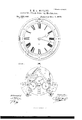
- Figure 1 represents in external elevation a clock-movement with invisible winding and regulating mechanism.
- Fig. 2 is a plan section of the same illustrating the new parts.
- Fig. 3 is an external view of the movement, the door of the case removed.
- Fig. at is an external view of the movement in front of the large plate, with the case removed.
- Figs. 5, 6, and 7 are the keys, shown in detail.
- the convex dial a is placed, as usual, on the seat I) of the case, and leaves this seat projecting all round in form of a crown, completely masked by the metal and covering part of the door 0.
- this crown are pierced the holes for the passage and play of three keys, at cf, whose heads rest on the seat I), embracing its circular form.
- Those (1 c are for winding the barrels, and that f for regulating the balance, Fi 3.
- the winding mechanism of the left barrel or striking-movenient G consists in mounting on the axis of this barrel a toothed wheel, h, and on a bridge borne by the great plate j an intermediate wheel, K.
- This bridge 6 by its projection, also serves as support to the pinion m of the key (Z.
- This pinion is pierced through- In drawing forward the key by the head (1 its square end (1 fits into the square hole of the pinion m, and so becomes solid with it.
- the click h drops into the teeth of the wheel h, and prevents its turning in a contrary direc tion to the arrow, Fig. 4.
- the winding mechanism of the barrel P of the going part consists of a toothed wheel, 0, fixed at the square end of the axis of the spiral spring, to gear with the intermediate wheel a, whose axis turns in the bridge q, borne by the great plate j, and the key 0, with cylindrical shaft 0 supplied with a pinion, 1.
- a small plate, 5, fixed to the small palletplate t, serves to guide the shaft 0 in its drawing forward movement, which motion is nec essary to cause the teeth of the pinion r, fixed to the key-shaft, to gear with the teeth of the intermediate wheel a, Figs. 4 and 6.
- the toothed wheel 0 can only turn from right to left, being checked by the click 0, Fi 4.
- the shaft a which, by the pinion u, governs thetoothed wheel a of the regulatingscrew, terminates square, and works freely in the hole or socket j, which constitutes the body of the key f, and which becomes solid with it when the key is drawn forward.
- the letters A R engraved on the key, indicate the directions to turn the key for making the clock fast or slow, or advance and retard, Fig. 3.
- a clock having one or more attached keys extending through its front plate outside of its dial, and covered and concealed by the door-frame when the door is closed, substantially as described.
- a clock having its dial carried by afront plate of greater diameter than said dial, the annular portion of said plate surrounding the dial being pierced within one or more apertures, coinciding with one or more shafts extendin g behind the front plate, and connected by gearing with winding or regulating mechanism, the said shafts being accessible for turning through the apertures of the said front plate, substantially as described.
Landscapes
- Physics & Mathematics (AREA)
- General Physics & Mathematics (AREA)
- Toys (AREA)
Description
E M L MAXANT. 2S11eetsSheet 1. Invisible Clock-Winding M h i No. 220,401. Patented Oct. 7,1879.
' FIG l.
N.PETERS, FHOTO-LITHOGRAPHER, WASHINGTON, D C.
UNITED STATES PATENT OFFICE.
EHENNE M. L. MAXANT, OF PARIS, FRANCE.
IMPROVEMENT IN INVISIBLE CLOCK-WINDING MECHANISMS.
Specification forming part of Letters Patent No. 220. 101, dated October 7, 1879; application filed April 1. 1879; patented in France, March 5, 1879.
To all whom it may concern:
Be, it known that I, ETIENNE MATHURIN LEON MAxAN'r, of the city of Paris, in the Republic of France, have invented certain Improvements in Invisible Olock-IVinding Mechanisms, with permanently located keys, of which the following is a specification.
The object of this invention is to wind the striking and going parts of clocks, and to regulate them in such a manner that the clockface is not disfigured by the customary winding-places, as visible on clocks at present manufactured. This is eifected by concealing the keys (which are permanently located) beneath the door of the clock-case.
The improvements requisite for carrying this into elfect are as follows:
First, as regards the winding of the springbarrel of the striking part, a toothed wheel is fixed on the shaft or arbor of the barrelsprin This wheel is actuated by another, and this again by a pinion. This pinion is pierced in the center with. a square hole, which is traversed freely by the shaft of a key, whose head rests eccentrically on the dial beneath the door of the clock-case, which conceals it. Its end terminates square, and is of the same dimensions as the square aperture in the pinion, so that in winding up the head of the hiddenkey is first drawn forward, which causes its square end to fix in the square of the pinion, and so renders it solid with it. The key is then turned in the usual way for windin Second, in winding the spring-barrel of the going part in a similar manner, by having a toothed wheel fixed to the axis of the spring, gearing with an intermediate wheel, which gears with a pinion fixed on the shaft of the key. WVhen this key is drawn forward and when the head rests on the face of the clock, the pinion un gears and the wheel is liberated.
Third, in regulating the balance by a key entering and withdrawing like the preceding, which becomes solid with the regulating rod, which terminates square for the purpose.
Having so far described my invention, I will now proceed to explain the mode of carrying it into effect by aid of the accompanying drawings, at the same time indicating the claims and modifications of which it is susceptible.
Figure 1 represents in external elevation a clock-movement with invisible winding and regulating mechanism. Fig. 2 is a plan section of the same illustrating the new parts. Fig. 3 is an external view of the movement, the door of the case removed. Fig. at is an external view of the movement in front of the large plate, with the case removed. Figs. 5, 6, and 7 are the keys, shown in detail.
\Vhen the case is closed, as shown in Fig. 1, neither axis nor hole is visible on the dial. The lines and figures denoting the hours can thus occupy the room they require, leaving space for ornamentation and design.
The convex dial a is placed, as usual, on the seat I) of the case, and leaves this seat projecting all round in form of a crown, completely masked by the metal and covering part of the door 0. In this crown are pierced the holes for the passage and play of three keys, at cf, whose heads rest on the seat I), embracing its circular form. Those (1 c are for winding the barrels, and that f for regulating the balance, Fi 3.
\Vhen the door 0 with glass v is closed, the heads of the keys (Z c fare concealed and held in a circular groove, 0, of this door. Screws cl f for each key admit of screwing them more to less, to prevent the least play of these organs.
In winding the barrels or regulating the balance, the door is opened, the heads of the keys are then drawn forward, and are then turned, as usual, which effects, as will be explained, the winding and regulating under precisely the same conditions, as usual.
On the drawings I have shown the three modes of construction explained above.
The winding mechanism of the left barrel or striking-movenient G, consists in mounting on the axis of this barrel a toothed wheel, h, and on a bridge borne by the great plate j an intermediate wheel, K. This bridge 6, by its projection, also serves as support to the pinion m of the key (Z. This pinion is pierced through- In drawing forward the key by the head (1 its square end (1 fits into the square hole of the pinion m, and so becomes solid with it.
The click h drops into the teeth of the wheel h, and prevents its turning in a contrary direc tion to the arrow, Fig. 4.
The winding mechanism of the barrel P of the going part consists of a toothed wheel, 0, fixed at the square end of the axis of the spiral spring, to gear with the intermediate wheel a, whose axis turns in the bridge q, borne by the great plate j, and the key 0, with cylindrical shaft 0 supplied with a pinion, 1.
A small plate, 5, fixed to the small palletplate t, serves to guide the shaft 0 in its drawing forward movement, which motion is nec essary to cause the teeth of the pinion r, fixed to the key-shaft, to gear with the teeth of the intermediate wheel a, Figs. 4 and 6.
The toothed wheel 0 can only turn from right to left, being checked by the click 0, Fi 4.
For the regulating mechanism, Figs. 2, 3, and 7, the shaft a, which, by the pinion u, governs thetoothed wheel a of the regulatingscrew, terminates square, and works freely in the hole or socket j, which constitutes the body of the key f, and which becomes solid with it when the key is drawn forward.
The letters A R, engraved on the key, indicate the directions to turn the key for making the clock fast or slow, or advance and retard, Fig. 3.
In conclusion, it should be observed, first, that the wheel work and the general movement is not altered; second, that the winders of the barrels may be'constructed as shown, Figs. 5, 6, 7, 2, and 4; third, that while dis posing the heads of the keys 0 d f as shown, Figs. 1 and 4, they can be rendered solid with the organs governing the axes of the barrels or the regulating-shaft by any appropriate mechanical combinations, differing but little from those described and represented by the drawings.
I claim as my invention-- 1. A clock having one or more attached keys extending through its front plate outside of its dial, and covered and concealed by the door-frame when the door is closed, substantially as described.
2. A clock having its dial carried by afront plate of greater diameter than said dial, the annular portion of said plate surrounding the dial being pierced within one or more apertures, coinciding with one or more shafts extendin g behind the front plate, and connected by gearing with winding or regulating mechanism, the said shafts being accessible for turning through the apertures of the said front plate, substantially as described.
3. The combination, with the barrel G, of the striking mechanism mounted in suitable bearings, of the toothed wheel h, mounted on the axis of said barrel, the pinion m, havinga hollow arbor and connected with said toothed wheel by gearing, and the key-shaft niovable longitudinally within said hollow arbor, and adapted to carry the pinion with it when drawn forward and rotated, substantially as described.
4. The combination, with the winding-arbor P of the spring of the going mechanism, of the toothed wheel 0, longitudinally-sliding key-shaft 6 carrying pinion 1', adapted to be connected by gearing with wheel 0 when said shaft is drawn forward, substantially as described,
5. The combination, with the shaft a, connected by intermediate gearing with the reg ulatin g mechanism of the clock, and provided with the square tip X on its extended front end, the tubular longitudinally-movable keybodyf surrounding said extended front end, and having in its inner end wall a square hole to fit the square tip thereof, and provided with the head f in'front of the front plate, I), sub stantially as described.
E. M. L. MAXANT.
Witnesses:
A. BL'ETRY, J. PERREY.
Publications (1)
| Publication Number | Publication Date |
|---|---|
| US220401A true US220401A (en) | 1879-10-07 |
Family
ID=2289802
Family Applications (1)
| Application Number | Title | Priority Date | Filing Date |
|---|---|---|---|
| US220401D Expired - Lifetime US220401A (en) | maxant |
Country Status (1)
| Country | Link |
|---|---|
| US (1) | US220401A (en) |
-
0
- US US220401D patent/US220401A/en not_active Expired - Lifetime
Similar Documents
| Publication | Publication Date | Title |
|---|---|---|
| US220401A (en) | maxant | |
| US78972A (en) | Improvement in time-pieces | |
| US267104A (en) | piquet | |
| US202795A (en) | Improvement in clocks | |
| US293779A (en) | Dayid pbeeet | |
| US672728A (en) | Winding and setting watch. | |
| US358997A (en) | Mechanism | |
| US323795A (en) | William b | |
| US2235068A (en) | Mantel clock | |
| US473424A (en) | Calendar-clock | |
| US311594A (en) | masmejai | |
| US442301A (en) | Auguste aharon | |
| US801306A (en) | Time-alarm. | |
| US1410050A (en) | Clock and watch | |
| US517594A (en) | Job smith | |
| US126620A (en) | Improvement in clock attachments to gas-burners | |
| US371539A (en) | Stem winding and setting watch | |
| US161262A (en) | Improvement in stem-winding watches | |
| US418128A (en) | Watch | |
| US767605A (en) | Musical alarm-clock. | |
| US381219A (en) | Stem winding and setting watch | |
| US720259A (en) | Stem winding and setting watch. | |
| US288075A (en) | Stem setting attachment foe watches | |
| US82266A (en) | Improvement in clocks | |
| US364105A (en) | Watch |