US2204012A - Air conditioning apparatus - Google Patents
Air conditioning apparatus Download PDFInfo
- Publication number
- US2204012A US2204012A US251965A US25196539A US2204012A US 2204012 A US2204012 A US 2204012A US 251965 A US251965 A US 251965A US 25196539 A US25196539 A US 25196539A US 2204012 A US2204012 A US 2204012A
- Authority
- US
- United States
- Prior art keywords
- chamber
- core
- aperture
- shaft
- housing
- Prior art date
- Legal status (The legal status is an assumption and is not a legal conclusion. Google has not performed a legal analysis and makes no representation as to the accuracy of the status listed.)
- Expired - Lifetime
Links
- 238000004378 air conditioning Methods 0.000 title description 14
- 238000005192 partition Methods 0.000 description 19
- XLYOFNOQVPJJNP-UHFFFAOYSA-N water Substances O XLYOFNOQVPJJNP-UHFFFAOYSA-N 0.000 description 10
- 229910000746 Structural steel Inorganic materials 0.000 description 6
- 239000000463 material Substances 0.000 description 4
- 239000008400 supply water Substances 0.000 description 3
- 239000013521 mastic Substances 0.000 description 2
- 239000002184 metal Substances 0.000 description 2
- 229910052751 metal Inorganic materials 0.000 description 2
- 238000005452 bending Methods 0.000 description 1
- 230000001143 conditioned effect Effects 0.000 description 1
- 230000003750 conditioning effect Effects 0.000 description 1
- 238000001816 cooling Methods 0.000 description 1
- 230000000284 resting effect Effects 0.000 description 1
- 230000000717 retained effect Effects 0.000 description 1
Images


Classifications
-
- F—MECHANICAL ENGINEERING; LIGHTING; HEATING; WEAPONS; BLASTING
- F24—HEATING; RANGES; VENTILATING
- F24F—AIR-CONDITIONING; AIR-HUMIDIFICATION; VENTILATION; USE OF AIR CURRENTS FOR SCREENING
- F24F3/00—Air-conditioning systems in which conditioned primary air is supplied from one or more central stations to distributing units in the rooms or spaces where it may receive secondary treatment; Apparatus specially designed for such systems
-
- F—MECHANICAL ENGINEERING; LIGHTING; HEATING; WEAPONS; BLASTING
- F24—HEATING; RANGES; VENTILATING
- F24F—AIR-CONDITIONING; AIR-HUMIDIFICATION; VENTILATION; USE OF AIR CURRENTS FOR SCREENING
- F24F6/00—Air-humidification, e.g. cooling by humidification
- F24F6/02—Air-humidification, e.g. cooling by humidification by evaporation of water in the air
- F24F6/04—Air-humidification, e.g. cooling by humidification by evaporation of water in the air using stationary unheated wet elements
Definitions
- This invention relates to improvements in air conditioning apparatus.
- the general object of the invention is to provide an improved device for circulating cooled or heated air.
- Another object of the invention is to provide an air conditioning device wherein the conditioned air does not come in direct contact with the conditioning means.
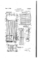
- Fig. 1 is a vertical longitudinal section through my improved air conditioning apparatus
- Fig. 2 is a section taken on line 22 of Fig. 1;
- Fig. 3 is a section taken on line 33 of Fig. 1;
- Fig. 4 is a fragmentary section taken online 44 of Fig. 1;
- Fig. 5 is a section taken on line 55 of Fig. 1;
- Fig. 6 is a fragmentary elevation of one side of the apparatus
- Fig. '7 is a fragmentary section taken on line 'I--'! of Fig. 6 with the chain guard removed;
- Fig. 8 is a fragmentary view similar to Fig. 1 showing the intake air damper in the position it occupies when the apparatus operates to heat air;
- Fig. 9 is a view similar to Fig. 4 showing a modified form of core member in the device
- Fig. 10 is a fragmentary section of the device taken on line Ill-l0 of Fig. 9;
- Fig. 11 is an enlarged fragmentary section taken on line II-Il of Fig. 10;
- Fig. 12 is a fragmentary enlarged section of the core taken on line I 2--
- Fig. 13 is a fragmentary enlarged section taken on line l3-l3 of Fig. 10.
- the apparatus l0 includes a housing IIv having end walls l2 and I3, side walls l4 and I5 and a bottom .wall l6. Intermediate the ends l2 and iii the housing I I has a transverse vertical partition I'I therein formingchambers I8 and I9 within the housing.
- the top of the chamber I9 is closed by a top member 20.
- the end, side and partition wall of the chamber l8 extend above the top member 20 to form a flanged portion 2
- a head member 22 which includes end walls 23 and 24, side walls 25 and 26 and a top wall 21.
- a head member 28 surrounding the head member 22 together with the side and end walls of the head 55 member forms a. groove in which the housing (o1. sa -13s) flange 2
- the top wall 21 has an. outlet aperture 29 therein surrounded by an upwardly projecting flange 30 and an outlet aperture 3
- I provide a short length of conduit 32 which extends a predetermined distance below and above the top wall 21.
- Adjacent the aperture 29 I provide a transversely extending shaft 33 which is supported in bearing members 34 on the side walls 25 and 26.
- the side wall 25 is apertured as at 35 and the shaft 33 extends outwardly through the aperturev 35 (see Fig. 3).
- Mounted on the shaft exterior of the header member I provide a hub member 36 which has a rod 31 extending therefrom at right angles to the shaft 33 and has a weighted member 38 thereon.
- the flap mem-' ber 39 when in one position is adapted to restrict passage through the conduit 32 as shown in Fig. 1 and in another position to restrict passage through the aperture 29.
- the weighted member 38 retains the flap 39 in either of its two extreme positions. 25
- the end wall l3 has an elongated outlet aperture 4
- the partition wall I! has an elongated inlet aperture 43 therein and below the support 49 an elongated inlet aperture 44.
- Flanges 45 are formed at the sides and top of the aperture. 43 by turning the metal of the partition wall outwardly towards the chamber I9 and similar flanges 46 are provided at the sides and bottom of the aperture 44.
- a water supply conduit 54 Extending into the chamber I8 below the supports 40 through the side wall I4 I provide a water supply conduit 54. Exterior to the housing the conduit 54 communicates through a shut off valve 55 with a water supply pipe 56. Interposed in the conduit 54 within the chamber I0 I provide float actuated control valve 51.
- includes a lower plate 62 which rests on the supports 40 and an upper plate 63.
- the plates 62 and 83 each has a plurality of spaced elongated apertures 84 therein which extend parallel to the side walls I4 and I5 Isee Fig. 3).
- each of the conduits is crenulated to form a tortuous passage therethrough.
- each of the conduits 85 I provide a vertical partition member 66 which extends upwardly from the lower plate 62 a predetermined distance.
- the core conduits 65 form a plurality of tortuous vertical passageways from the lower chamber 66 to the upper chamber 81 and a plurality of horizontal passageways from the inlet aperture 43 to the outlet aperture 4I. surrounded by a flange 68' opening into the chamber I9 (see Fig. 2).
- the blower I0 includes a drive shaft II having a sprocket I2 thereon which is adapted to be driven through the medium of a sprocket chain I3 from a sprocket I4 on the armature shaft of an electric motor I5.
- the motor I5 is arranged in an aperture I6 in the bottom I6 and is supported by suitable brackets 11.
- the motor is encased by an end wall 18, a side wall I9 and a top wall to isolate it from the chamber I8.
- the blower I0 includes an outlet portion 8
- the opposite or outlet end of the distributor conduit 82 engages the flanges 45 and 46 and encompasses the apertures 43 and 44.
- the bottom of the conduit 82 has an aperture 83 therein which is adapted to be closed by a flap 84.
- the flap 84 is mounted on a shaft 85 which is supported in bearing members 86 on the side Walls I4 and I5.
- the bearing 88 on the wall I4 extends through a suitable aperture in the wall and the shaft 85 extends outwardly beyond the end of the bearing where it has a sprocket 8'I thereon (see Figs. 5 and 7).
- the side wall I4 has an inlet aperture 68 sprocket 81 the shaft 85 has a hub member 88 thereon which has an arm 89 extending therefrom at right angles to the shaft 85.
- brackets 90 .I provide a vertical rod 9I which adjacent the upper end is slackly connected to the arm 89 as indicated at 92.
- inlet apertures 43 and 44 I provide a flange member 93 extending into the distributor conduit 82.
- the flap 84 engages the bottom of the distributor conduit 82 and forms a closure for the aperture 83 asshown in Fig. 1.
- the flap 84 engages the flange 93 thereby aifordingunrestricted passageway through the aperture 83 into the distributor conduit and at the same time forming a partition to restrict passage from the blower outlet 8I to the inlet aperture 44 of the lower chamber 66 (see Fig. 8).
- a heat chamber 95 which is formed by the bottom of the distributor conduit 82, a portion of the partition II, a portion of the motor housing wall I8, a pair of spaced side walls 96 and an inclined top wall 91.
- a gas burner memberg98 which includes a portion extending out through the side wall I4 of the housing which communicates through a control valve 99 with a pipe I00 from a source of gas supply.
- the control valve 99 includes an operating stem IOI on which is mounted a segmental actuating plate I02 having an aperture I03 therein.
- a segmental actuating plate I02 having an aperture I03 therein.
- the control valve 99 cannot be actuated to an open position until the flap 84 is raised to an up position.
- the plate I02 prevents the rod 9I from being lowered thereby preventing the flap 84 to be moved to a down position.
- the shaft 33 of the head member 22 has a gear I05 thereon which meshes with an idler gear I06 which in turn meshes with an enlarged'gear I01.
- the idler gear I06 is mounted on a stud shaft I08 which is supported in-a bearing I09 and the gear I0'I is mounted on a shaft IIO which is suitably journaled in a bearing II2.
- Also mounted on the shaft III] I provide a sprocket II3 which is connected with the sprocket 81 by a sprocket chain II4.
- connection between the shaft 33 and the shaft 85 is such that when the flap 39 is in a position to restrict passage through the conduit 32 the flap 84 is in a position to restrict passage through the distributor aperture 83 as shown in Fig. 1.
- the flap 84 is moved to an up position to restrict passage from the blower outlet 8I to the inlet aperture 44 of the lower chamber 66 and afford unrestricted passage from the heat chamber 95 through the aperture 83 to the inlet aperture 44 as shown in Fig. 8.
- the armature shaft of the motor I5 extends outwardly through a suitable aperture in the side wall I5 and has'a sprocket II5 thereon which is connected by a sprocket chain I I8 to the sprocket 49 on the disc shaft 41.
- conduit H1 When the device I is installed in a house a conduit H1 is provided one end of which communicates with the head aperture 29 and the opposite end of which may open into the attic of the house. One end of a conduit 8 communicates with the head conduit 32 and the opposite end may open into the attic or open to the outside atmosphere. If desired ,an inlet conduit I I9 may be provided having one end communicatin with the inlet aperture 68 and the opposite end with the outside atmosphere.
- of the device I0 may be made as shown in the drawings or a conduit or series of conduits (not shown) may communicate therewith to direct air to various desired locations;
- the head flap 39 When it is desired to condition air by cooling it the head flap 39 is swung to the position shown in Fig. 1 with the flap 84 moved to a down position as previously described.
- the lower chamber is filled with water to a predetermined level as previously described.
- the motor 15 is then started which then drives the blower I0 and rotates the discs 5
- a portion of the air from the blower passes through the inlet aperture 43 into the chamber I8 and a portion passes through the inlet aperture 44 into the lower chamber 60'.
- the air going into the lower chamber 66' absorbs some of the water thrown off of the discs 5
- This cooled air then passes upwardly through the tortuous passageways in the core conduits 65 into the upper chamber '61 and thence through the aperture 29 into the conduit into the chamber I8 passes upwardly'between the conduits 65 over the tops of the partitions 86 and thence downwardly and out through the outlet aperture 4
- the head flap 39 When the device I0 is to be used to heat air passing through the chamber I8 the head flap 39 is swung to restrict passage through the aperture 29 and afford unrestricted passage through the conduit 32. As the head flap 39 is thus moved the distributor conduit flap 84 is movedmaterial I4 I.
- the core member I20 includes a plurality of spaced rectangularly shaped vertical cell members I2I.
- Each of the cells I2I is formed of a single sheet of metal and includes side walls I22 connected by a continuous front wall I23 and a rear wall I24.
- the rear wall I24 is formed by bending the ends of the side walls towards each other and connecting thereby'a folded joint as indicated at I25.
- each includes an outwardly bent flange I26 which is connected to the outwardly bent flange of the adjacent cell by a joint which might be termed a step joint as indicated at I2I.
- the side walls I22 each includes an outwardly bent flange I28 whichis connected to the outwardly bent flange of the adjacent cell by a folded joint as indicated at I29.
- the horizontal flange of the upper frame I3I overlies the top of the adjacent cells and between the cells and the horizontal flange I provide a layer of mastic material I33.
- the horizontal flange of the lower frame I32 underlies the bottom of the adjacent cells and between the cells and the horizontal flange I provide a layer of plastic material I34.
- the upper and lower frames are secured in position on the cells by a plurality of bolts I35 the countersunk heads I36 of which are positioned in similarly countersunk apertures I31 in the horizontal flanges of the upper ,frame I3I. Adjacent the lower ends thereof the bolts I35 include threaded portions I38 which are r positioned in threaded apertures I39 in the horizontal flanges of the lower frame I32.
- a layer of mastic material I40 is placed on the angle iron frame 40. Thereafter the core member I20 is positioned in the chamber I8 with the horizontal flange of the lower core frame I32 resting on the plastic I40. After the core I20 has been positioned in the chamber I8a layer of plastic material MI is placed on the upper surface of horizontal flanges of the upper frame I3I.
- An angle iron clamp frame I42 is positioned on top of the plastic At the front and sides of the housing II the clamp frame I42 is secured to an outer encompassing channel iron frame portion I43 of the housing II by a plurality of bolts I44 and nuts I45.
- the core member I20 functions in a similar manner to that previously described in connection with the core member 6
- a housing having atransverse vertical partition therein forming two compartments, one of said compartments including a core chamber and a lower chambenja core member positioned in said core chamber, said core-member comprising a plurality of spaced elongated vertical conduits, said housing having an outlet in the upper portion of conduits and extending upwardly from the bot- "tom ofsaid core chamber, air moistening means in said lower chamber and means in the other compartment to force moistened air from said lower chamber through said core conduits and to force air around said core conduits.
- a housing having a transverse vertical partition therein forming compartments, one of said compartments including a core chamber and a lower chamber, a core positioned in said core chamber, said core member comprising a plurality of spaced elongated vertical conduits, each of said core conduits having a tortuous passageway therethrough, said housing having an outlet in the upper portion thereof, said housing having an outlet from' said core chamber adjacent the lower end thereof, said partition having an aperture therein adjacent the lower end of said core chamber, said partition having an aperture adjacent the top, of said lower chamber, a partition member between said core conduits and extending upwardly from the bottom of the core chamber, a blower member in said housing, said blower including an outlet portion, a distributor conduit communicating at one end with said blower outlet and at the opposite end with the partition aperturea'and air moistening means in said lower chamber.
- a housing including a core chamber and a lower chamber, a core member positioned in said core chamber, said core member comprising spaced conduits, each having a tortuous passageway therethrough, said housing having an outlet at the top, said core chamber having an inlet and an outlet adjacent the lower end thereof, said lower chamber having an entrance aperture adjacent the top of said lower chamber, a partition member between each" of said core conduits extending upwardly from the bottom of the core chamber and terminating below thetop thereof, a blower member in said housing, said blower including an outlet portion, a distributor conduit communicating at one end with said blower outlet and at the opposite end with said core chamger inlet and said lower chamber inlet, a shaft in said lower compartment, means to rotate said shaft and a plurality of discs on said shaft and rotatable therewith.
- a housing including an intermediate chamber, a lower chamber and an upper chamber, a core member positioned in said intermediate chamber, said core member comprising spaced, vertical conduits, each of said conduits having a passageway therethrough, said housing having an exhaust aperture in the top thereof opening into said upper chamber, a movable closure flap in said upper chamber adapted in one position to restrict passage through said exhaust aperture, said housing having an exit aperture therein in said intermediate chamber adjacent the lower end thereof, said intermediate chamber .having an entrance aperture therein adjacent the lower end of said core chamber and said lower chamber having an entrance aperture adjacent the top of said lower chamber, a partition member between each of said core conduits extending upwardly from the bottom of said intermediate chamber and terminating below the top thereof, a blower member in said housing, said blower including an outlet portion, adistributor conduit communicating at one end with said blower outlet and at the opposite end with said core chamber inlet and said lower chamber lnlet, a transverse shaft in said lower compartment, means to support said shaft and means
- a housing including a core chamber and a lower chamber, a core member positioned in said core chamber, said core member comprising spaced, vertical conduits each having a passageway therethrough, said housing having an exhaust aperture, said housing having an outlet from said core chamber adjacent the lower end thereof, said core chamber having an inlet therein adjacent the lower end of said core chamber and said lower chamber having an entrance aperture adjacent the top of said lower chamber, a partition member between each of said core conduits extending upwardly from the bottom of said core chamber and terminating below the top thereof, a blower member in said housing, said blower including an outlet portion, a distributor conduit communicating at one end with said blower outlet and at theoppcsite end with said core chamber inlet and said lower chamber inlet, a transverse shaft in said lower compartment, means to support said shaft and means to rotate said shaft, a plurality of discs on said shaft and rotatable therewith, said discs being positioned one below each of the core conduits, and means to supply water to said lower compartment.
- a housing including a plurality of compartments, a core member positioned in one of said compartments, said core member comprising a plurality of spaced elongated vertical conduits, said housing having an outlet communicating with the interior of said conduits, said housing having a second outlet communicating with the exterior of said conduits, a blower member including an outlet communicating with the exterior and with the interior of said conduits, a shaft in said housing, means to support said shaft, a plurality of disks rotatable on said shaft, each disk being positioned below a core conduit, and means to supply water to said disks.
Landscapes
- Engineering & Computer Science (AREA)
- Chemical & Material Sciences (AREA)
- Combustion & Propulsion (AREA)
- Mechanical Engineering (AREA)
- General Engineering & Computer Science (AREA)
- Air-Flow Control Members (AREA)
Description
AIR CONDITIONING APPARATUS Filed Jan. 20, 1959 s Sheets-Sheet 1 Hal June 11, 1940. Q CQQK 2,204,12
AIR connrrxouma APPARATUS Filed Jan. 20, 1939 5 Sheets-Sheet 2 W QB 1N VENTOR.
(1B1 COOK.
ATTORNEY.
Patented June 11, 1940 UNITED STATES" AIR CONDITIONING APPARATUS Charles B. Cook,
Los Angeles, Calif.
Application January 20, 1939, Serial No. 251,965
.6 Claims.
This invention relates to improvements in air conditioning apparatus.
The general object of the invention is to provide an improved device for circulating cooled or heated air. v
Another object of the invention is to provide an air conditioning device wherein the conditioned air does not come in direct contact with the conditioning means. 1
Other objects and the advantages of this invention will be apparent from the following description taken in connection with the accompanying drawings, wherein:
Fig. 1 is a vertical longitudinal section through my improved air conditioning apparatus;
Fig. 2 is a section taken on line 22 of Fig. 1;
Fig. 3 is a section taken on line 33 of Fig. 1;
Fig. 4 is a fragmentary section taken online 44 of Fig. 1;
Fig. 5 is a section taken on line 55 of Fig. 1;
Fig. 6 is a fragmentary elevation of one side of the apparatus;
Fig. '7 is a fragmentary section taken on line 'I--'! of Fig. 6 with the chain guard removed;
Fig. 8 is a fragmentary view similar to Fig. 1 showing the intake air damper in the position it occupies when the apparatus operates to heat air;
Fig. 9 is a view similar to Fig. 4 showing a modified form of core member in the device;
Fig. 10 is a fragmentary section of the device taken on line Ill-l0 of Fig. 9;
Fig. 11 is an enlarged fragmentary section taken on line II-Il of Fig. 10;
Fig. 12 is a fragmentary enlarged section of the core taken on line I 2--|2 of Fig. 9'. and
Fig. 13 is a fragmentary enlarged section taken on line l3-l3 of Fig. 10.
Referring to the drawings by reference characters I have indicated my improved air conditioning apparatus generally at I0. As shown the apparatus l0 includes a housing IIv having end walls l2 and I3, side walls l4 and I5 and a bottom .wall l6. Intermediate the ends l2 and iii the housing I I has a transverse vertical partition I'I therein formingchambers I8 and I9 within the housing. The top of the chamber I9 is closed by a top member 20. The end, side and partition wall of the chamber l8 extend above the top member 20 to form a flanged portion 2|.
5o Mounted on the flanged portion 2| I provide a head member 22 which includes end walls 23 and 24, side walls 25 and 26 and a top wall 21. .A head member 28 surrounding the head member 22 together with the side and end walls of the head 55 member forms a. groove in which the housing (o1. sa -13s) flange 2| is positioned. The top wall 21 has an. outlet aperture 29 therein surrounded by an upwardly projecting flange 30 and an outlet aperture 3| of less area than the aperture 29. Positioned in the aperture 3| I provide a short length of conduit 32 which extends a predetermined distance below and above the top wall 21.
Adjacent the aperture 29 I provide a transversely extending shaft 33 which is supported in bearing members 34 on the side walls 25 and 26.
v The side wall 25 is apertured as at 35 and the shaft 33 extends outwardly through the aperturev 35 (see Fig. 3). Mounted on the shaft exterior of the header member I provide a hub member 36 which has a rod 31 extending therefrom at right angles to the shaft 33 and has a weighted member 38 thereon.
Mounted on the shaft 33 within the head member I provide a flap member 39. The flap mem-' ber 39 when in one position is adapted to restrict passage through the conduit 32 as shown in Fig. 1 and in another position to restrict passage through the aperture 29. The weighted member 38 retains the flap 39 in either of its two extreme positions. 25
Within the chamber I8 and a predetermined distance above the bottom I6 I provide angle iron support members 40 on the side walls 14 and I5, the end wall l3 and the partition I1.
Just above the support 40 the end wall l3 has an elongated outlet aperture 4| therein which is surrounded by a flange 42. Just above the support 40 the partition wall I! has an elongated inlet aperture 43 therein and below the support 49 an elongated inlet aperture 44. Flanges 45 are formed at the sides and top of the aperture. 43 by turning the metal of the partition wall outwardly towards the chamber I9 and similar flanges 46 are provided at the sides and bottom of the aperture 44.
Intermediate the end wall I3 and the partition wall l1 and intermediate the bottom [6 and the supports 40 I provide a transversely extending shaft 41 which is rotatably supported in bearings 48 on the side walls l4 and I5 (see Fig. 4). The bearing 48 on the side wall I5 extends out of the chamber l8 through a suitable aperture in the side wall l5 and the shaft 41 extends beyond the outer end of the bearing where it has a sprocket 49 mounted thereon. Between the bearings 48 the shaft includes a flattened portion 50. Mounted on the shaft 41 I provide a. plurality of spaced discs 5| which are apertured to conform to the shape of the shaft. The discs 5| are retained in a predetermined spaced relationship by a plurality of sleeve members 52. The periphery of each of the discs 5| is preferably formed saw toothed as indicated at 53.
Extending into the chamber I8 below the supports 40 through the side wall I4 I provide a water supply conduit 54. Exterior to the housing the conduit 54 communicates through a shut off valve 55 with a water supply pipe 56. Interposed in the conduit 54 within the chamber I0 I provide float actuated control valve 51.
When the valve 55 is opened water flows into the chamber I8 until the level thereof is slightly below the shaft 41 whereupon the float valve 51 closes. Thereafter the water level is automatically maintained by the float valve 51.
Communicating with the interior of the chamber I8 through the side wall I4 I preferably provide a water level gauge device 58.
Communicating with the interior of the chamber I8 through the bottom wall I8 I provide a drain conduit 59 having a shut off valve 60 interposed therein.
Positioned in the chamber I8 below the head member 22 I provide a core member 6I. The core member 6| includes a lower plate 62 which rests on the supports 40 and an upper plate 63. The plates 62 and 83 each has a plurality of spaced elongated apertures 84 therein which extend parallel to the side walls I4 and I5 Isee Fig. 3).
Between the plates 62 and 63 each of the conduits is crenulated to form a tortuous passage therethrough. Between each of the conduits 85 I provide a vertical partition member 66 which extends upwardly from the lower plate 62 a predetermined distance.
When the core BI is in a position in the chamber I8 a lower chamber 66' is provided in the chamber I8 and an upper chamber 61 is formed in the head member 22. The core conduits 65 form a plurality of tortuous vertical passageways from the lower chamber 66 to the upper chamber 81 and a plurality of horizontal passageways from the inlet aperture 43 to the outlet aperture 4I. surrounded by a flange 68' opening into the chamber I9 (see Fig. 2).
Mounted on a suitable support 69 within the chamber I9 I provide a centrifugal blower I0. The blower I0 includes a drive shaft II having a sprocket I2 thereon which is adapted to be driven through the medium of a sprocket chain I3 from a sprocket I4 on the armature shaft of an electric motor I5. The motor I5 is arranged in an aperture I6 in the bottom I6 and is supported by suitable brackets 11. The motor is encased by an end wall 18, a side wall I9 and a top wall to isolate it from the chamber I8.
The blower I0 includes an outlet portion 8| which communicates with the inlet end of a distributor conduit member 82. The opposite or outlet end of the distributor conduit 82 engages the flanges 45 and 46 and encompasses the apertures 43 and 44.
The bottom of the conduit 82 has an aperture 83 therein which is adapted to be closed by a flap 84. The flap 84 is mounted on a shaft 85 which is supported in bearing members 86 on the side Walls I4 and I5. The bearing 88 on the wall I4 extends through a suitable aperture in the wall and the shaft 85 extends outwardly beyond the end of the bearing where it has a sprocket 8'I thereon (see Figs. 5 and 7). Beyond the Positioned in the apertures 64 of the plates 62 and 63 I provide vertical conduit mem- The side wall I4 has an inlet aperture 68 sprocket 81 the shaft 85 has a hub member 88 thereon which has an arm 89 extending therefrom at right angles to the shaft 85.
Positioned in and reciprocatable through.- a pair of apertured brackets 90 .I provide a vertical rod 9I which adjacent the upper end is slackly connected to the arm 89 as indicated at 92.
Intermediate the inlet apertures 43 and 44 I provide a flange member 93 extending into the distributor conduit 82. In one position or the down position the flap 84 engages the bottom of the distributor conduit 82 and forms a closure for the aperture 83 asshown in Fig. 1. In another position or the. up position the flap 84 engages the flange 93 thereby aifordingunrestricted passageway through the aperture 83 into the distributor conduit and at the same time forming a partition to restrict passage from the blower outlet 8I to the inlet aperture 44 of the lower chamber 66 (see Fig. 8).
Below the distributor conduit 82 I provide a heat chamber 95 which is formed by the bottom of the distributor conduit 82, a portion of the partition II, a portion of the motor housing wall I8, a pair of spaced side walls 96 and an inclined top wall 91. Within the chamber 95 I provide a gas burner memberg98 which includes a portion extending out through the side wall I4 of the housing which communicates through a control valve 99 with a pipe I00 from a source of gas supply.
The control valve 99 includes an operating stem IOI on which is mounted a segmental actuating plate I02 having an aperture I03 therein. When the control valve 99 is \in a closed position as shown in Figs. 6 and '7 the aperture I03 in the plate I02 is in line with the brackets 90.
and when the flap 84 is inthe down position the rod 9| is positioned in the aperture I03. Thus the control valve 99 cannot be actuated to an open position until the flap 84 is raised to an up position. When the flap 84 is inan up position and the control valve 99 is open the plate I02 prevents the rod 9I from being lowered thereby preventing the flap 84 to be moved to a down position.
The shaft 33 of the head member 22 has a gear I05 thereon which meshes with an idler gear I06 which in turn meshes with an enlarged'gear I01. The idler gear I06 is mounted on a stud shaft I08 which is supported in-a bearing I09 and the gear I0'I is mounted on a shaft IIO which is suitably journaled in a bearing II2. Also mounted on the shaft III] I provide a sprocket II3 which is connected with the sprocket 81 by a sprocket chain II4.
The connection between the shaft 33 and the shaft 85 is such that when the flap 39 is in a position to restrict passage through the conduit 32 the flap 84 is in a position to restrict passage through the distributor aperture 83 as shown in Fig. 1. When the flap 39 is moved to restrict passage through the aperture 29 the flap 84 is moved to an up position to restrict passage from the blower outlet 8I to the inlet aperture 44 of the lower chamber 66 and afford unrestricted passage from the heat chamber 95 through the aperture 83 to the inlet aperture 44 as shown in Fig. 8.
The armature shaft of the motor I5 extends outwardly through a suitable aperture in the side wall I5 and has'a sprocket II5 thereon which is connected by a sprocket chain I I8 to the sprocket 49 on the disc shaft 41. Thus when the motor III operates the discs 5| are rotated in a direction towards the inlet aperture 44.
When the device I is installed in a house a conduit H1 is provided one end of which communicates with the head aperture 29 and the opposite end of which may open into the attic of the house. One end of a conduit 8 communicates with the head conduit 32 and the opposite end may open into the attic or open to the outside atmosphere. If desired ,an inlet conduit I I9 may be provided having one end communicatin with the inlet aperture 68 and the opposite end with the outside atmosphere.
The outlet aperture 4| of the device I0 may be made as shown in the drawings or a conduit or series of conduits (not shown) may communicate therewith to direct air to various desired locations;
When it is desired to condition air by cooling it the head flap 39 is swung to the position shown in Fig. 1 with the flap 84 moved to a down position as previously described. The lower chamber is filled with water to a predetermined level as previously described.
The motor 15 is then started which then drives the blower I0 and rotates the discs 5| through the means previously described. As the discs 5| rotate water adheres to them and is thrown off by centrifugal force into the space above the water level in the chamber 66. As the blower I0 operates air is drawn into the chamber I9 through the inlet aperture 68 and into the blower. From the outlet portion 8| of the blower a column of air under pressure is directed into the distributor conduit 82. v
A portion of the air from the blower passes through the inlet aperture 43 into the chamber I8 and a portion passes through the inlet aperture 44 into the lower chamber 60'. The air going into the lower chamber 66' absorbs some of the water thrown off of the discs 5| and is thus cooled. This cooled air then passes upwardly through the tortuous passageways in the core conduits 65 into the upper chamber '61 and thence through the aperture 29 into the conduit into the chamber I8 passes upwardly'between the conduits 65 over the tops of the partitions 86 and thence downwardly and out through the outlet aperture 4| As the air thuspasses through the chamber I8 it contacts the chilled conduits 65 and in turn becomes chilled.
When the device I0 is to be used to heat air passing through the chamber I8 the head flap 39 is swung to restrict passage through the aperture 29 and afford unrestricted passage through the conduit 32. As the head flap 39 is thus moved the distributor conduit flap 84 is movedmaterial I4 I.
modified form of core member generally at I20 which may be used in the device I0 in place of the core member 6|. As shown the core member I20 includes a plurality of spaced rectangularly shaped vertical cell members I2I. Each of the cells I2I is formed of a single sheet of metal and includes side walls I22 connected by a continuous front wall I23 and a rear wall I24. The rear wall I24 is formed by bending the ends of the side walls towards each other and connecting thereby'a folded joint as indicated at I25.
At the upper end the side. walls I22 each includes an outwardly bent flange I26 which is connected to the outwardly bent flange of the adjacent cell by a joint which might be termed a step joint as indicated at I2I. Similarly at the lower end the side walls I22 each includes an outwardly bent flange I28 whichis connected to the outwardly bent flange of the adjacent cell by a folded joint as indicated at I29. When a plurality of the cells I2I are thus connected together they form passageways I30 therebetween.
Around the upper edge of the plurality of connected cells I2I I provide an angle iron frame I3| and around the lower edge I provide an angle iron frame I32. The horizontal flange of the upper frame I3I overlies the top of the adjacent cells and between the cells and the horizontal flange I provide a layer of mastic material I33.
The horizontal flange of the lower frame I32 underlies the bottom of the adjacent cells and between the cells and the horizontal flange I provide a layer of plastic material I34.
The upper and lower frames are secured in position on the cells by a plurality of bolts I35 the countersunk heads I36 of which are positioned in similarly countersunk apertures I31 in the horizontal flanges of the upper ,frame I3I. Adjacent the lower ends thereof the bolts I35 include threaded portions I38 which are r positioned in threaded apertures I39 in the horizontal flanges of the lower frame I32.
When the core member I20 is positioned in the chamber I8 of the device I0 a layer of mastic material I40 is placed on the angle iron frame 40. Thereafter the core member I20 is positioned in the chamber I8 with the horizontal flange of the lower core frame I32 resting on the plastic I40. After the core I20 has been positioned in the chamber I8a layer of plastic material MI is placed on the upper surface of horizontal flanges of the upper frame I3I. An angle iron clamp frame I42 is positioned on top of the plastic At the front and sides of the housing II the clamp frame I42 is secured to an outer encompassing channel iron frame portion I43 of the housing II by a plurality of bolts I44 and nuts I45.
The core member I20 functions in a similar manner to that previously described in connection with the core member 6| except that the core member I20 allows water thrown from the disks 5| to wet the entire wall above each disk so that high efficiency may be secured.
From the foregoing description it will be apparent that I have provided an improved air conditioning apparatus which is simple in con- 7 struction and highly efficient in use.
Having thus described my invention I claim: 1. In an air conditioning device, a housing having atransverse vertical partition therein forming two compartments, one of said compartments including a core chamber and a lower chambenja core member positioned in said core chamber, said core-member comprising a plurality of spaced elongated vertical conduits, said housing having an outlet in the upper portion of conduits and extending upwardly from the bot- "tom ofsaid core chamber, air moistening means in said lower chamber and means in the other compartment to force moistened air from said lower chamber through said core conduits and to force air around said core conduits.
2. In an air conditioning device, a housing having a transverse vertical partition therein forming compartments, one of said compartments including a core chamber and a lower chamber, a core positioned in said core chamber, said core member comprising a plurality of spaced elongated vertical conduits, each of said core conduits having a tortuous passageway therethrough, said housing having an outlet in the upper portion thereof, said housing having an outlet from' said core chamber adjacent the lower end thereof, said partition having an aperture therein adjacent the lower end of said core chamber, said partition having an aperture adjacent the top, of said lower chamber, a partition member between said core conduits and extending upwardly from the bottom of the core chamber, a blower member in said housing, said blower including an outlet portion, a distributor conduit communicating at one end with said blower outlet and at the opposite end with the partition aperturea'and air moistening means in said lower chamber.
3. In an air conditioning device, a housing including a core chamber and a lower chamber, a core member positioned in said core chamber, said core member comprising spaced conduits, each having a tortuous passageway therethrough, said housing having an outlet at the top, said core chamber having an inlet and an outlet adjacent the lower end thereof, said lower chamber having an entrance aperture adjacent the top of said lower chamber, a partition member between each" of said core conduits extending upwardly from the bottom of the core chamber and terminating below thetop thereof, a blower member in said housing, said blower including an outlet portion, a distributor conduit communicating at one end with said blower outlet and at the opposite end with said core chamger inlet and said lower chamber inlet, a shaft in said lower compartment, means to rotate said shaft and a plurality of discs on said shaft and rotatable therewith.
4. In an air conditioning device, a housing including an intermediate chamber, a lower chamber and an upper chamber, a core member positioned in said intermediate chamber, said core member comprising spaced, vertical conduits, each of said conduits having a passageway therethrough, said housing having an exhaust aperture in the top thereof opening into said upper chamber, a movable closure flap in said upper chamber adapted in one position to restrict passage through said exhaust aperture, said housing having an exit aperture therein in said intermediate chamber adjacent the lower end thereof, said intermediate chamber .having an entrance aperture therein adjacent the lower end of said core chamber and said lower chamber having an entrance aperture adjacent the top of said lower chamber, a partition member between each of said core conduits extending upwardly from the bottom of said intermediate chamber and terminating below the top thereof, a blower member in said housing, said blower including an outlet portion, adistributor conduit communicating at one end with said blower outlet and at the opposite end with said core chamber inlet and said lower chamber lnlet, a transverse shaft in said lower compartment, means to support said shaft and means to rotate said shaft, a plurality of discs on said shaft androtatable therewith, said discs being positioned one below each of the core conduits, the periphery of said discs being formed saw toothed and means to supply water to said lower compartment.
5. In an air conditioning device, a housing including a core chamber and a lower chamber, a core member positioned in said core chamber, said core member comprising spaced, vertical conduits each having a passageway therethrough, said housing having an exhaust aperture, said housing having an outlet from said core chamber adjacent the lower end thereof, said core chamber having an inlet therein adjacent the lower end of said core chamber and said lower chamber having an entrance aperture adjacent the top of said lower chamber, a partition member between each of said core conduits extending upwardly from the bottom of said core chamber and terminating below the top thereof, a blower member in said housing, said blower including an outlet portion, a distributor conduit communicating at one end with said blower outlet and at theoppcsite end with said core chamber inlet and said lower chamber inlet, a transverse shaft in said lower compartment, means to support said shaft and means to rotate said shaft, a plurality of discs on said shaft and rotatable therewith, said discs being positioned one below each of the core conduits, and means to supply water to said lower compartment.
6. In an air conditioning device, a housing including a plurality of compartments, a core member positioned in one of said compartments, said core member comprising a plurality of spaced elongated vertical conduits, said housing having an outlet communicating with the interior of said conduits, said housing having a second outlet communicating with the exterior of said conduits, a blower member including an outlet communicating with the exterior and with the interior of said conduits, a shaft in said housing, means to support said shaft, a plurality of disks rotatable on said shaft, each disk being positioned below a core conduit, and means to supply water to said disks.
CHARLES E. COOK.
Priority Applications (1)
| Application Number | Priority Date | Filing Date | Title |
|---|---|---|---|
| US251965A US2204012A (en) | 1939-01-20 | 1939-01-20 | Air conditioning apparatus |
Applications Claiming Priority (1)
| Application Number | Priority Date | Filing Date | Title |
|---|---|---|---|
| US251965A US2204012A (en) | 1939-01-20 | 1939-01-20 | Air conditioning apparatus |
Publications (1)
| Publication Number | Publication Date |
|---|---|
| US2204012A true US2204012A (en) | 1940-06-11 |
Family
ID=22954107
Family Applications (1)
| Application Number | Title | Priority Date | Filing Date |
|---|---|---|---|
| US251965A Expired - Lifetime US2204012A (en) | 1939-01-20 | 1939-01-20 | Air conditioning apparatus |
Country Status (1)
| Country | Link |
|---|---|
| US (1) | US2204012A (en) |
Cited By (4)
| Publication number | Priority date | Publication date | Assignee | Title |
|---|---|---|---|---|
| US2481149A (en) * | 1945-04-17 | 1949-09-06 | Adolphe C Peterson | Air-conditioning and heating means |
| US2483509A (en) * | 1947-01-11 | 1949-10-04 | Arthur A Soderman | Air conditioning apparatus |
| US3903213A (en) * | 1974-01-02 | 1975-09-02 | Randall S Stover | Counter flow, forced draft, blow-through heat exchangers |
| US4273733A (en) * | 1979-07-30 | 1981-06-16 | Niagara Blower Company | Apparatus for cooling fluids |
-
1939
- 1939-01-20 US US251965A patent/US2204012A/en not_active Expired - Lifetime
Cited By (4)
| Publication number | Priority date | Publication date | Assignee | Title |
|---|---|---|---|---|
| US2481149A (en) * | 1945-04-17 | 1949-09-06 | Adolphe C Peterson | Air-conditioning and heating means |
| US2483509A (en) * | 1947-01-11 | 1949-10-04 | Arthur A Soderman | Air conditioning apparatus |
| US3903213A (en) * | 1974-01-02 | 1975-09-02 | Randall S Stover | Counter flow, forced draft, blow-through heat exchangers |
| US4273733A (en) * | 1979-07-30 | 1981-06-16 | Niagara Blower Company | Apparatus for cooling fluids |
Similar Documents
| Publication | Publication Date | Title |
|---|---|---|
| US4361525A (en) | Air cooling apparatus | |
| US2178176A (en) | Air conditioner | |
| US2266219A (en) | a larriva | |
| US2204012A (en) | Air conditioning apparatus | |
| US3958628A (en) | Vertical blower coil unit for heating and cooling | |
| US1846875A (en) | Air conditioning | |
| US2170993A (en) | Air conditioning | |
| US2205716A (en) | Unit heater and air conditioner | |
| US2122482A (en) | Air conditioning apparatus | |
| US4774030A (en) | Evaporative cooler having efficient air transfer system | |
| US2528720A (en) | Air conditioning apparatus for heating and cooling | |
| US2029153A (en) | Refrigeration process and apparatus | |
| US1933771A (en) | Air conditioning device | |
| US2222524A (en) | Display case | |
| US2066832A (en) | Humidifying and temperature control apparatus for citrus fruit storages and like structures | |
| US2128245A (en) | Combined air conditioner and furnace | |
| US2142289A (en) | Air conditioning apparatus | |
| US2265634A (en) | Refrigerating plant | |
| US2243281A (en) | Humidifier | |
| US1966632A (en) | Air conditioner | |
| US2134802A (en) | Air conditioning device | |
| US2173405A (en) | Method and apparatus for conditioning air | |
| US1476441A (en) | Heating system | |
| US1950347A (en) | Air washer and humidifier | |
| US2265497A (en) | Refrigerating apparatus |