US2203550A - Electric lamp - Google Patents
Electric lamp Download PDFInfo
- Publication number
- US2203550A US2203550A US107190A US10719036A US2203550A US 2203550 A US2203550 A US 2203550A US 107190 A US107190 A US 107190A US 10719036 A US10719036 A US 10719036A US 2203550 A US2203550 A US 2203550A
- Authority
- US
- United States
- Prior art keywords
- filament
- discharge
- lamp
- resistance
- envelope
- Prior art date
- Legal status (The legal status is an assumption and is not a legal conclusion. Google has not performed a legal analysis and makes no representation as to the accuracy of the status listed.)
- Expired - Lifetime
Links
- 208000028659 discharge Diseases 0.000 description 68
- 239000007789 gas Substances 0.000 description 16
- 238000009834 vaporization Methods 0.000 description 13
- 230000008016 vaporization Effects 0.000 description 13
- 238000001704 evaporation Methods 0.000 description 10
- 238000010438 heat treatment Methods 0.000 description 10
- 239000001257 hydrogen Substances 0.000 description 10
- 229910052739 hydrogen Inorganic materials 0.000 description 10
- UFHFLCQGNIYNRP-UHFFFAOYSA-N Hydrogen Chemical compound [H][H] UFHFLCQGNIYNRP-UHFFFAOYSA-N 0.000 description 9
- 230000008020 evaporation Effects 0.000 description 9
- XKRFYHLGVUSROY-UHFFFAOYSA-N Argon Chemical compound [Ar] XKRFYHLGVUSROY-UHFFFAOYSA-N 0.000 description 8
- 239000000463 material Substances 0.000 description 7
- 229910052751 metal Inorganic materials 0.000 description 7
- 239000002184 metal Substances 0.000 description 7
- 238000005286 illumination Methods 0.000 description 6
- QSHDDOUJBYECFT-UHFFFAOYSA-N mercury Chemical compound [Hg] QSHDDOUJBYECFT-UHFFFAOYSA-N 0.000 description 6
- 229910052753 mercury Inorganic materials 0.000 description 6
- 239000000203 mixture Substances 0.000 description 5
- 238000013021 overheating Methods 0.000 description 5
- 230000005855 radiation Effects 0.000 description 5
- 238000012546 transfer Methods 0.000 description 5
- IJGRMHOSHXDMSA-UHFFFAOYSA-N Atomic nitrogen Chemical compound N#N IJGRMHOSHXDMSA-UHFFFAOYSA-N 0.000 description 4
- 229910052786 argon Inorganic materials 0.000 description 4
- 238000001816 cooling Methods 0.000 description 3
- 230000001066 destructive effect Effects 0.000 description 3
- 230000000694 effects Effects 0.000 description 3
- 230000001105 regulatory effect Effects 0.000 description 3
- PXHVJJICTQNCMI-UHFFFAOYSA-N Nickel Chemical compound [Ni] PXHVJJICTQNCMI-UHFFFAOYSA-N 0.000 description 2
- 238000009835 boiling Methods 0.000 description 2
- 230000015556 catabolic process Effects 0.000 description 2
- 238000010276 construction Methods 0.000 description 2
- 239000011261 inert gas Substances 0.000 description 2
- 150000002739 metals Chemical class 0.000 description 2
- 238000012986 modification Methods 0.000 description 2
- 230000004048 modification Effects 0.000 description 2
- 229910052757 nitrogen Inorganic materials 0.000 description 2
- 238000010792 warming Methods 0.000 description 2
- 238000003466 welding Methods 0.000 description 2
- HCHKCACWOHOZIP-UHFFFAOYSA-N Zinc Chemical compound [Zn] HCHKCACWOHOZIP-UHFFFAOYSA-N 0.000 description 1
- 238000010521 absorption reaction Methods 0.000 description 1
- 230000001154 acute effect Effects 0.000 description 1
- 229910052793 cadmium Inorganic materials 0.000 description 1
- BDOSMKKIYDKNTQ-UHFFFAOYSA-N cadmium atom Chemical compound [Cd] BDOSMKKIYDKNTQ-UHFFFAOYSA-N 0.000 description 1
- 238000006243 chemical reaction Methods 0.000 description 1
- 230000000295 complement effect Effects 0.000 description 1
- 239000012809 cooling fluid Substances 0.000 description 1
- 230000006378 damage Effects 0.000 description 1
- 230000003247 decreasing effect Effects 0.000 description 1
- 230000007812 deficiency Effects 0.000 description 1
- 238000010494 dissociation reaction Methods 0.000 description 1
- 230000005593 dissociations Effects 0.000 description 1
- 238000000295 emission spectrum Methods 0.000 description 1
- 239000012530 fluid Substances 0.000 description 1
- 150000002431 hydrogen Chemical class 0.000 description 1
- 230000001771 impaired effect Effects 0.000 description 1
- 229910001338 liquidmetal Inorganic materials 0.000 description 1
- 229910052754 neon Inorganic materials 0.000 description 1
- GKAOGPIIYCISHV-UHFFFAOYSA-N neon atom Chemical compound [Ne] GKAOGPIIYCISHV-UHFFFAOYSA-N 0.000 description 1
- 229910052759 nickel Inorganic materials 0.000 description 1
- 239000012858 resilient material Substances 0.000 description 1
- 238000007789 sealing Methods 0.000 description 1
- 239000007787 solid Substances 0.000 description 1
- 238000001228 spectrum Methods 0.000 description 1
- WFKWXMTUELFFGS-UHFFFAOYSA-N tungsten Chemical compound [W] WFKWXMTUELFFGS-UHFFFAOYSA-N 0.000 description 1
- 229910052721 tungsten Inorganic materials 0.000 description 1
- 239000010937 tungsten Substances 0.000 description 1
- 238000004804 winding Methods 0.000 description 1
- 229910052725 zinc Inorganic materials 0.000 description 1
- 239000011701 zinc Substances 0.000 description 1
Images

Classifications
-
- H—ELECTRICITY
- H01—ELECTRIC ELEMENTS
- H01J—ELECTRIC DISCHARGE TUBES OR DISCHARGE LAMPS
- H01J61/00—Gas-discharge or vapour-discharge lamps
- H01J61/96—Lamps with light-emitting discharge path and separately-heated incandescent body within a common envelope, e.g. for simulating daylight
-
- Y—GENERAL TAGGING OF NEW TECHNOLOGICAL DEVELOPMENTS; GENERAL TAGGING OF CROSS-SECTIONAL TECHNOLOGIES SPANNING OVER SEVERAL SECTIONS OF THE IPC; TECHNICAL SUBJECTS COVERED BY FORMER USPC CROSS-REFERENCE ART COLLECTIONS [XRACs] AND DIGESTS
- Y10—TECHNICAL SUBJECTS COVERED BY FORMER USPC
- Y10S—TECHNICAL SUBJECTS COVERED BY FORMER USPC CROSS-REFERENCE ART COLLECTIONS [XRACs] AND DIGESTS
- Y10S315/00—Electric lamp and discharge devices: systems
- Y10S315/05—Starting and operating circuit for fluorescent lamp
Definitions
- This invention relates to gaseous electrical discharge devices and especially to those in which charge starts so that the voltage of the discharge is substantially increased thereby. More particularly this invention relates to a combination of such electrical discharge device with a radiant series resistance.
- Another object of the invention is to provide a vapor discharge device, and especially a high pressure vapor discharge lamp, in which means is provided for hastening the heating-up period during which the pressure is increased to its 5 normal operating value.
- Another object ofthe invention is to provide a combined gaseous discharge and incandescent light source in which the deficiency of the gaseous discharge spectrum are made up by radiat'lon from the incandescent source.
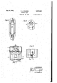
- Fig. 1 is a view partly in longitudinal section of a typical high pressure vapor lamp for general illumination purposes having incandescent filament therein according to my invention.
- Fig. 2 is a view in cross section taken on line 2-2 of Fig. 1.
- Fig. 3 is a view in cross section showing a lamp 3( similarto that of Fig. 1, but having special means for protecting the filaments against overload.
- Fig. 4 is a view partly in side elevation, partly in vertical section of another embodiment of my invention.
- Fig. 5 is a view in perspective of still another embodiment of my invention.
- Fig. 6 is a fragmentary view similar to the upperportion of Fig. 5 but showing another modification.
- Fig. 7 is a view partly in vertical section and partly in side elevation of another embodiment of my invention.
- t Fig. 8 is a fragmentary view in axial section of anotherembodiment of my invention.
- FIG. 1 I have shown there a lamp for general illumination purposes.
- An inner envelope Iii serves to enclose the atmosphere in which theelectrical discharge takes place between the fixed solid electrodes ll mounted on the lead-in wires l2.
- This inner envelope I0 is supported within an outer jacket l3 bymeans of a framework l5-IE the construction of which is clearly shown in the drawings and which is advantageously made of 'nickel or other resilient material, so asto avoid breakage of the envelope l during shipment, etc.
- the upper part l6 of the mounting frame is connected by the flexible connection 22 to the lead-in wire l2 of the upper electrode and is shaped so that it is engaged between the upper domed end of the jacket l3 and the upper end of the envelope l0. 7
- connections l8 and 22 are not essential and the lead wirescan be welded directly to" the frame parts l and I9, but I prefer by means of these flexible connections to relieve the seals between the envelope Ill and the lead-in wires I! of any possible strain which may result from direct welding to the frame.
- the longitudinal wire members of the frame portions l5 and I6 extend, between the insulating discs l'l, along the sides of the envelope iii.
- This discharge in turn heats the electrodes ll, converting the initial discharge to an arc.
- the discharge operates with a minimum voltage, and a maximum current; and a maximum loading is, therefore, imposed uponv the filaments 25, with a corresponding tendency to overheat these filaments to a brilliant white incandescence. It is.
- a suitable convection gas is provided within the jacketl3.
- This may be an inert gas such as has been used heretofore in incandescent lamp scribed and claimed in a prior application Serlak bulbs. g" argon, nitrogen, etc" or mixtures of No.
- the size of the filament wires is designed so that with all of these paths operating in parallel and with the envelope lfl'at full operating temperature, these filaments will be at low incandescence, giving a veryred' radiation.
- the envelope i0 is filled with a starting gas such as argon, neon, etc., at low pressure and with a supply of a'vapo'rizable material such as for example, mercury in amount sufllcient when vaporized to increase the resistance of the discharge path so that the voltage drop within the envelope l0 between the electrodes II is substantially increased after starting of the dis-- charge.
- the jacket I3 is filled with a suitable gas inert with respect to the filament, e. g., argon, or nitrogen or hydrogen, or mixtures of such gases as more fully described below.
- an atmosphere of pure hydrogen may be used in the jacket I3
- the unit may be made self-contained for operation from constant potential circuit,.whereas with the use of parallel discharges as described as an alternative of Fig. 1, or parallel filaments as in Fig. 3, additional ballast outside the lamp would obviously be used in the operation as described.
- the vaporizable filling within the envelope I0 is preferably chosen to give an emission spectrum which is strongest in the violet, blue, green and yellow-green and preferably one which is fairly complete in that range so as to complement the low incandescence of the filament which radi ates mostly in the red, orange and orange-yellow;
- Fig. 3 I have shown another device adapted to provide further protection for the filament during the initial heating-up period, while the voltage requirement of the main discharge is low.
- thermostatic contact 30 is secured to the disc I'Ia corresponding to the lower disc I! of Fig. 1 and is connected to the frame l5 as shown.
- is secured at ill to the 7 disc “a as shown, andisbowed over the end of the thermostatic strip 3
- Filament wires 32 are connected from the frame members I6 to a book 33 on the strip 3
- the filaments 32 are connected through the strips 30 and 3
- a tube 34 or other suitable baflle member is preferably placed over the thermostat 30 to intercept heat transfer from the filament while permitting direct inter-change of heat with the envelope I 0. Ordinarily, however, this will not be necessary if the strip 30 is welded at one endto the member I5 close beside the envelope i0 and extended therealong on the opposite side of the envelope from the filament wires 32.
- Fig. 4 I have shown another embodiment of my invention in which the series resistance filament is enclosed within a separate bulb 40 within the jacket l3b.
- the discharge envelope lllb can be around the incandescent lamp bulb 40 as closely as possible so as to be in heat-exchange relation thereto; but at best this arrangement is less advantageous than that described above because the closed bulb 40 tends to limit the heat exchange between the two.
- the principal advantage of this arrangement is that standard discharge and incandescent lamps can be combined in a fixture without the necessity of sealing the two together, and therefore if the filament should burn out due to over-load this can be more readily replaced.
- Fig. 5 is shown another alternative similar to that of Fig. 1 but using a simpler and less rugged mounting.
- the filament wires 25c run longitudinally along the lamp, instead of in zig-zag, between the frame members I50 and lie.
- Fig. 6,1 have shown still another lamp similar to that of Fig. 5, but using a spiral filament 25d supported by the frame "id at one end of the lamp instead of the parallel longitudinal filament.
- I may also use a plurality of metals, as for example a mixture of mercury, cadmium and zinc, or a mixture of mercury and other higher boiling point metals.
- a plurality of metals as for example a mixture of mercury, cadmium and zinc, or a mixture of mercury and other higher boiling point metals.
- the incandescent filament is to be operated at a temperature of maximum practicable efficiency, as for example where it is protected during the initial starting period by a short-circuiting discharge or by the parallel or substituted filament as illustrated for example in Figs. 8 and andemciency 'of the incandescent'lamp will be less impaired.
- the lamp is designed to reach equilibrium without total evaporation of the vaporizable metal. e. g., as described in my application, 8erlal No. 558,148, filed August 19, 1931.
- Fig. 8 shows a ballast resistance coil 25! surrounding the pump tip 50 at the lowest part of the lamp.
- the liquid metal collects in this depression and as soon as the discharge begins is strongly heated by the resistance coil 25! so that it is very quickly evaporated.
- the resistance 25f may advantageously be only a protecting parallel resistance switched into the circuit only during starting and thus corresponding to the filament 32 of Fig. 3.
- the heater 25 may be in series or parallel with other lighting filaments and the tip 50 may be so remote from the discharge that it controls the pressure of at least the highest boiling point metal in the tube, lllf. Thus if an overload condition occurs this heater will evaporate more metal and with under-load will allow metal to condense and thereby keep the loading of the filaments approximately at the best temperature for life and efiiciency.
- a radiant electrical discharge device having a vaporizable filling therein adapted by vaporization to at least double the voltage drop in the discharge device and a radiant ballast resistance therefor, in which the ballast resistance is in heat-exchange relation to the discharge device such that during initial operation the heat generated in the ballast resistance is utilized to hasten the vaporization of the filling in the discharge device and during the initial low voltage operation before vaporization of the filling and in other case of overload, the thermal capacity and heat dissipating capacity of the dis-' charge device will absorb excessive heat developed in the ballast resistance and protect it against destructive over-heating.
- an electrical discharge device which comprises an envelope, a filling within said envelope including a vaporizable material adapted to provide a gaseous medium for the discharge and by vaporization to increase the voltage of the discharge, electrodes spaced therein, lead-in' connections, an incandescent filament connected in series to one of said lead-in connections, adapted to be heated by the current of the discharge and positioned outside but in heat-exchange relation to the envelope a substantially closed jacket enclosing the envelope and filament, and a heat transfer gas in said jacket which includes hydrogen.
- a vapor electric discharge device having a vaporizable filling adapted by vaporization to at least double the voltage drop of the discharge device and an incandescent filament in series therewith in a gas adapted to break down and carry a discharge across the filament at a voltage less than sumcient to cause destructive overheating of the filament, and the filament and its connections are adapted to sustain such discharge only above the voltage applied to the filament in normal operation.
- a vapor electric discharge device having a vaporizable filling adapted by vaporization to increase the voltage drop of its discharge, an incandescent filament in series therewith, means in parallel to said filament for carrying at least a part of the discharge current during the warming-up period of the discharge while its voltage consumption is low, and means to discontinue the current through said parallel means after the warming-up.
- a vapor electric discharge device having a vaporizable filling adapted by vaporization to increase the voltage drop of the discharge and an incandescent filament in series therewith, and means adapted to protect thefilament'against excessive heating by increased current during the warming-up period of the discharge while its voltage drop is low
- the means for carrying discharge current during the starting period comprises an auxiliary filament in parallel to the first named filament and a switch therefor responsive to conditions resulting from evaporation of the vaporizable filling adapted to break the circuit of said auxiliary filament and leave the first named filament in series with the lamp.
- a vapor electric discharge device having a vaporizable filling adapted by vaporization to increase the voltage drop of the discharge and an incandescent filament in series therewith, and means adapted to protect the filament against excessive heating by increased current during the warming-up period of the discharge while its voltage drop is low
- the means for carrying discharge current during thestarting period comprises an auxiliary filament in parallel to the first named filament and a thermostatic switch therefor responsive to temperature resulting from evaporation of the vaporizable filling adapted to break the circuit of said auxiliary filament, and leave the first named filament in series with the lamp.
- ballast resistance therefor, a molecular cooling fluid over said resistance adapted to be decomposed -by heat generated by said resistor and with an endothermic reaction and to recombine at lower temperature with liberation of heat of combination and means for holding said fluid over said resistance.
- a vapor electric discharge lamp having a vaporizable filling adapted by vaporization to increase the voltage drop of the discharge and an incandescent filament lamp in series therewith, and means adapted to increase the resistance in series with the discharge during the warming up period of the discharge while its voltage drop is low whereby to protect said filament against overload, said increased resistance being less than will fully compensate for the lower voltage of the discharge whereby the current is temporarily increased for heating the discharge lamp and for supplying greater illumination from the filament lamp.
- a vapor electric discharge device having a vaporizable filling adapted by vaporization to increase the voltage drop of the discharge and an incandescent filament in series therewith, and means adapted to protect the filament against excessive heating with increased current during the warming up period of the discharge while its voltage drop-ls low, said protecting means being less than sufilcient to fully compensate for the lower voltage of the discharge, whereby the current is temporarily increased for heating the discharge lamp and for supplying greater illumination from the filament lamp while the voltage or the discharge is at its lowest value.
- a lighting circuit which comprises a source of current, a vapor electric discharge lamp having a vaporizable filling adapted by vaporization to increase the voltage drop of the discharge and an incandescent variable filament lamp in series therewith, and means for switching the filament circuit so that the filament effectively in the circuit during the starting period is adapted to reach incandescence in the circuit with a higher voltage drop than, that of the filament in the circuit during normal operation, and the filament in the circuit during normal operation is adapted to maintain incandescence with the voltage drop available to it during said normal operation.
- a vapor arc lamp of the type which increases its voltage to a substantially predetermined extent by evaporation of a limited supply of vaporizable material, and a plurality of incandescent filaments connected in parallel with each other and in series with the lamp, each carrying a relatively small part of the total arc current whereby any one may become disabled without seriously impairing the operation of the arc lamp or the other filaments.
- a lamp comprising in combination a vapor arc lamp of the type which increases its voltage by evaporation of a vaporizable material therein, an incandescent filament ballast, and means for supportig said incandescent filament, which combination is characterized by having a fixed body in intimate heat exchange relation to the incandescent filament substantially throughout the incandescent length of the filament and having a heat absorbing capacity sufiicient to prevent burning out of the filament due'to overloading in the first moments after the arc and filament are energized and until the arc voltage has been increased by vaporization of its filling material.
- a lamp comprising in combination a vapor arc lamp of the type which increases its voltage by evaporation of a vaporizable material therein, an incandescent filament ballast, and means for supporting said incandescent filament, which combination is characterized by having the filament in intimate heat-exchange relation to the envelope of the vapor arc lamp whereby the heat developed by the filament during the starting period is utilized for vaporization of the vaporizable filling in said-envelope and thereby the heatng up period is reduced and the filament protected against excessive overheating.
Landscapes
- Discharge Lamps And Accessories Thereof (AREA)
Description
June 4,1940. H. J. sPANNER ELECTRIC LAMP Filed. Oct. 23, 1936 2 SheetsSheet 1 INVENTOR A s M N J? I T J A M 2 Sheets-Sheet 2 H. J. SPANNER ELECTRIC LAMP Filed Oct. 23, 1936 llllll June 4, 1940.
INVENTOR HANS I SPAN/VE'R /7 y v ATTOR Y5 Patented June}, 1940 UNITED STATES PATENT OFFICE 2,203,550 ntnc'rmc LAMP Hans J. Spanner, Berlin, Germany Application mm 23, 1930, Serial No. 107.190
' 16 Claims. (01. rye-1 This invention relates to gaseous electrical discharge devices and especially to those in which charge starts so that the voltage of the discharge is substantially increased thereby. More particularly this invention relates to a combination of such electrical discharge device with a radiant series resistance.
This application is a continuation in part of my prior applications Serial No. 397,429, filed on October 4, 1929, Serial No. 558,148, filedAugust 19, 1931, Serial No. 643,502, filed November 19, 1932 now Patent #2991363, Serial No. 744,206, filed September 15, 193i, and Serial No. 51,390,
filed November 25,1935.
One of the problems of eiiicient use of gas discharge devices as sources of illumination is the loss of energy in the baliasting device. This is particularly true in D. 0. operation or in other cases where a resistance is used rather than a reactance. It has been suggested to use. resistance devices capable of giving useful radiation and thereby to utilize some of the energy dissipated in the ballasting resistance. An important obstacle has stood in the way of the complete success of this suggestion, namely, that the gaseous discharge devices are subject to substantial fiuctuation in voltage drop with variations in conditions of operation and normal variations in line voltage, with the result that it is difilcult to design a ballasting resistance device which can operate as an eflicient source of useful radiation without being subjected at times to seriousoverloading such as would reduce its useful life.
This difl'iculty is especially acute in the case of the so-called high pressure vapor lamps in which the pressureand the voltage in the lamp rise substantially afterthe discharge is started. With such lamps ifthe ballast resistance is efficiently designed for normal operation it will,
under ordinary circumstances, be seriously overloaded during the initial starting period before the pressure has reached its normal operating value.
Accordingly, it is an object of the present invention to provide a combination of a radiant discharge device and a radiant baliasting resistance in which the resistance is protected against over-load and the energy which otherwise would tend to deteriorate the resistance during the over-load condition is utilized for regulating the operation of the discharge device, e. g., by evaporating mercury.
Another object of the invention is to provide a vapor discharge device, and especially a high pressure vapor discharge lamp, in which means is provided for hastening the heating-up period during which the pressure is increased to its 5 normal operating value.
Another object ofthe invention is to provide a combined gaseous discharge and incandescent light source in which the deficiency of the gaseous discharge spectrum are made up by radiat'lon from the incandescent source.
In the accompanying drawings are shown several preferred embodiments of my invention and certain modifications thereof. These are not intended to be exhaustive or limiting of the invention, but are chosen for purposes of illustration in order that others skilled in the art may fully understand the principles of the invention andtheir application in practical use, and that they may have no difiiculty in applying the in ventionin numerous other forms according to the requirements of various conditions and special problems.
Fig. 1 is a view partly in longitudinal section of a typical high pressure vapor lamp for general illumination purposes having incandescent filament therein according to my invention.
Fig. 2 is a view in cross section taken on line 2-2 of Fig. 1.
Fig. 3 is a view in cross section showing a lamp 3( similarto that of Fig. 1, but having special means for protecting the filaments against overload.
Fig. 4 is a view partly in side elevation, partly in vertical section of another embodiment of my invention. Fig. 5 is a view in perspective of still another embodiment of my invention.
Fig. 6 is a fragmentary view similar to the upperportion of Fig. 5 but showing another modification.
Fig. 7 is a view partly in vertical section and partly in side elevation of another embodiment of my invention; and t Fig. 8 is a fragmentary view in axial section of anotherembodiment of my invention.
Referring first toFig. 1, I have shown there a lamp for general illumination purposes. An inner envelope Iii serves to enclose the atmosphere in which theelectrical discharge takes place between the fixed solid electrodes ll mounted on the lead-in wires l2.
This inner envelope I0 is supported within an outer jacket l3 bymeans of a framework l5-IE the construction of which is clearly shown in the drawings and which is advantageously made of 'nickel or other resilient material, so asto avoid breakage of the envelope l during shipment, etc.
'As'will be observed from the drawings, the
to one of the contacts on the base 2l, e. .g., a
standard Edison Mogul base.
The upper part l6 of the mounting frame is connected by the flexible connection 22 to the lead-in wire l2 of the upper electrode and is shaped so that it is engaged between the upper domed end of the jacket l3 and the upper end of the envelope l0. 7
The connections l8 and 22 are not essential and the lead wirescan be welded directly to" the frame parts l and I9, but I prefer by means of these flexible connections to relieve the seals between the envelope Ill and the lead-in wires I! of any possible strain which may result from direct welding to the frame.
As will be observed the longitudinal wire members of the frame portions l5 and I6 extend, between the insulating discs l'l, along the sides of the envelope iii. In order to give further support and also to provide a capacity along the side of the envelope to assist in starting (as demembers lS-IB and connections "-42 and 22-42 to the electrodes 1!, and there serves to break down the gas filling between the electrodes and establish a discharge. This discharge in turn heats the electrodes ll, converting the initial discharge to an arc. At this point the discharge operates with a minimum voltage, and a maximum current; and a maximum loading is, therefore, imposed uponv the filaments 25, with a corresponding tendency to overheat these filaments to a brilliant white incandescence. It is.
an advantage of my combination lamp that at this stage, while the illumination from the discharge is at relatively low intensity, the intensity of the incandescent filaments is substantially increased, and furthermore the color from the filament is substantially white. Without special precaution to protect the filament, however, there wouldbe serious danger of destructive overheating at this stage and consequent burning out of the filaments. It is an advantage of the construction shown,'however, that these filaments are in intimate heat-exchange relation .to the envelope l0 which, at this stage of operation, is 1 relatively cool. There is,'therefore, a rapid transfer of heat by radiation and convection from the filament to the envelope, which has the double advantage of protecting the filament against over-heating and of; hastening the evaporation of the vaporizable filling within the envelope Hi.
In order to give full efiect of this heat trans fer, a suitable convection gas is provided within the jacketl3. This may be an inert gas such as has been used heretofore in incandescent lamp scribed and claimed in a prior application Serlak bulbs. g" argon, nitrogen, etc" or mixtures of No. 744,206) these are brought as close as posible to the wall of the envelope l0, preferably without quite touching it, so as to avoid.possi ble contact of the base 2| to the lower electrode and the shell of the base to the lower portion ii of the frame, but that direct connection from the base to the upper electrode is made only through the filament wires 25, which are hung in zig-zag arrangement between the longitudinal members of the frame is and I6, and are supported thereon by the fine looped wires 26 welded to the frame members, or by welding directly to, or winding around the frame members. I It will be observed that this arrangement of the filament provides numerous parallel paths for passage of the current between the frame portions l5 and It. The size of the filament wires is designed so that with all of these paths operating in parallel and with the envelope lfl'at full operating temperature, these filaments will be at low incandescence, giving a veryred' radiation. The envelope i0 is filled with a starting gas such as argon, neon, etc., at low pressure and with a supply of a'vapo'rizable material such as for example, mercury in amount sufllcient when vaporized to increase the resistance of the discharge path so that the voltage drop within the envelope l0 between the electrodes II is substantially increased after starting of the dis-- charge. The jacket I3 is filled with a suitable gas inert with respect to the filament, e. g., argon, or nitrogen or hydrogen, or mixtures of such gases as more fully described below.
In the operation of this device a voltage is impressed upon the lamp across the terminals of the base and conducted, substantially without decrease, through the filaments 25 and the frame such gases, .at pressures sumciently high to avoid any short-circuiting discharge across the filament 3!, e.'g.,- about one-half atmosphere, but I have found it particularly advantageous to use a gas having a'high heat transfer capacity. Hydrogen gas is particularly suitable for this purpose, probably because at temperatures below those at which destruction of the tungsten filament occurs and above the temperatures of the filament in normal operation, the hydrogen is decomposed from the molecular state to the atomic state with absorption of large amounts of heat from the filament which are carried to and yielded up to cooler surfaces, as for example the surface of the envelope II. The expansion in volume and decrease in density of the gas due to this dissociation also facilitate the convection circulation of gases over the filament and the envelope. This arrangement,- therefore, has, the known action of the so-called iron-hydrogen" resistance, with the additional advantage that its heat is utilized for rapidly bringing the arc lamp to operating temperature. Obviously the overloadprotection action of the hydrogen atmosphere around the hot resistance wire can be utilized elsewhere than in the concentric jacket for apart or all of the ballast for the arc lamp.
Although an atmosphere of pure hydrogen may be used in the jacket I3, I prefer to use a mixture of hydrogen and an inert gas, for example hydrogen and argon.
In the above I have referred to theuse of a convection gas in the jacket at a pressure such that no short-circuiting discharge will occur across the filament. In one embodiment of my invention, however, such a discharge may be taken advantage of. to protect the filaments against overloading. Thus if the gaseous filling in the jacket is at a pressure regulated to break down at the voltage at which the maximum temperature of the filament is reached the gas itself will serve as a protection for the filament. In such case the initial operation is exactly as described above, namely the full voltage is imposed through the filament upon the electrodes, a break-down occurs within the envelope and the initial discharge is converted into an are by heating of the electrodes. At this point, however, the voltage within the envelope has become so low and consequently the voltage imposed on the filament is so high that the heated filamen will cause substantial ionization of the gas aroun it, and a breakdown of the gas will occur along the filaments 25 in parallel with the filament current. This dischargehowever, can continue only so long as the discharge in the envelope ll) remains at low voltage and so long as the filament remains hot enough to provide the necessary electron emission. As soon as the voltage consumption in the main discharge increases due to the evaporation of the mercury and the temperature of the filament is consequently decreased the remaining voltagewill be insufilcient to sustain the external discharge, and consequently the further operation of the lamp at normal operating temperature will continue exactlyas in the case described above.
It will. be understood by those skilled in the art that .where a discharge is to be permitted 30, in parallel to the filament 25 this must never be permitted to become an independent discharge, but must at all times depend upon the heating of the filament so that, upon cooling of the filament whether due to short-circuiting bythe discharge itself or to the increased voltage requirement of the main discharge the electrode drop of the .short-circuiting discharge will rise above the voltag. drop of the filaments when carrying the entire current and thus these auxiliary short-circuiting discharges will be extinguished. In no case can the ballasting effect of the resistances be completely destroyed by the short-circuiting discharges. In Figs. 1, 4, 5, 6 and '7 the unit may be made self-contained for operation from constant potential circuit,.whereas with the use of parallel discharges as described as an alternative of Fig. 1, or parallel filaments as in Fig. 3, additional ballast outside the lamp would obviously be used in the operation as described.
The vaporizable filling within the envelope I0 is preferably chosen to give an emission spectrum which is strongest in the violet, blue, green and yellow-green and preferably one which is fairly complete in that range so as to complement the low incandescence of the filament which radi ates mostly in the red, orange and orange-yellow;
and it is furthermore preferably chosen so as to raise the envelope ID to a relatively high temperature at which it will help to sustain the incandcscence of the filament by reducing the cooling effect of radiation andconvection. Both ofthese effects are produced with greatest advantage by a. high pressure mercury filling e. g., of one or more atmospheres of pressure during normal operation.
' In Fig. 3, I have shown another device adapted to provide further protection for the filament during the initial heating-up period, while the voltage requirement of the main discharge is low.
In In this case a bimetallic, thermostatic contact 30 is secured to the disc I'Ia corresponding to the lower disc I! of Fig. 1 and is connected to the frame l5 as shown.
A fixed contact strip 3| is secured at ill to the 7 disc "a as shown, andisbowed over the end of the thermostatic strip 3|] so as to make contact therewith when the thermostat is cool but leave room for the thermostatic strip 30 to move out of contact when it is heated by the lamp. Filament wires 32 are connected from the frame members I6 to a book 33 on the strip 3|. Thus when the lamp is cold and until it has reacheda temperature at which the increased voltage in the main discharge will protect the filament wires 25 the filaments 32 are connected through the strips 30 and 3| and the hook 33 in parallel with the filament 25 and the size of the filament wires 32 is regulated so that during the initial over-load period all of these parallel filaments will be at high incandescence but well below the temperatures at which burning out of the filament would occur.
. In order that the thermostat 30 may be primarily responsive to the temperature of the envelope l0 rather than to the temperature created by the filaments 25 and 32 a tube 34 or other suitable baflle member is preferably placed over the thermostat 30 to intercept heat transfer from the filament while permitting direct inter-change of heat with the envelope I 0. Ordinarily, however, this will not be necessary if the strip 30 is welded at one endto the member I5 close beside the envelope i0 and extended therealong on the opposite side of the envelope from the filament wires 32.
In Fig. 4, I have shown another embodiment of my invention in which the series resistance filament is enclosed within a separate bulb 40 within the jacket l3b. In this case the discharge envelope lllb can be around the incandescent lamp bulb 40 as closely as possible so as to be in heat-exchange relation thereto; but at best this arrangement is less advantageous than that described above because the closed bulb 40 tends to limit the heat exchange between the two. The principal advantage of this arrangement is that standard discharge and incandescent lamps can be combined in a fixture without the necessity of sealing the two together, and therefore if the filament should burn out due to over-load this can be more readily replaced.
In Fig. 5, is shown another alternative similar to that of Fig. 1 but using a simpler and less rugged mounting. In this case the filament wires 25c run longitudinally along the lamp, instead of in zig-zag, between the frame members I50 and lie.
In Fig. 6,1 have shown still another lamp similar to that of Fig. 5, but using a spiral filament 25d supported by the frame "id at one end of the lamp instead of the parallel longitudinal filament.
Instead of a single vaporizable metal, Imay also use a plurality of metals, as for example a mixture of mercury, cadmium and zinc, or a mixture of mercury and other higher boiling point metals. This is particularly advantageous where the incandescent filament is to be operated at a temperature of maximum practicable efficiency, as for example where it is protected during the initial starting period by a short-circuiting discharge or by the parallel or substituted filament as illustrated for example in Figs. 8 and andemciency 'of the incandescent'lamp will be less impaired. This is especially advantageous where the lamp is designed to reach equilibrium without total evaporation of the vaporizable metal. e. g., as described in my application, 8erlal No. 558,148, filed August 19, 1931.
In 'Fig. 7, I have shown another device similar to that of Fig. 4, but in this case a special lamp for starting or the lighter filament for normal operation will be connected in series with the gaseous discharge lamp according to the temperature of the thermostatic switch.
An enclosing jacket lie in this case is not essential but is highly desirable. Fig. 8 shows a ballast resistance coil 25! surrounding the pump tip 50 at the lowest part of the lamp. The liquid metal collects in this depression and as soon as the discharge begins is strongly heated by the resistance coil 25! so that it is very quickly evaporated. I The resistance 25f may advantageously be only a protecting parallel resistance switched into the circuit only during starting and thus corresponding to the filament 32 of Fig. 3. Or the heater 25 may be in series or parallel with other lighting filaments and the tip 50 may be so remote from the discharge that it controls the pressure of at least the highest boiling point metal in the tube, lllf. Thus if an overload condition occurs this heater will evaporate more metal and with under-load will allow metal to condense and thereby keep the loading of the filaments approximately at the best temperature for life and efiiciency.
I claim:
l. The combination of a radiant electrical discharge device having a vaporizable filling therein adapted by vaporization to at least double the voltage drop in the discharge device and a radiant ballast resistance therefor, in which the ballast resistance is in heat-exchange relation to the discharge device such that during initial operation the heat generated in the ballast resistance is utilized to hasten the vaporization of the filling in the discharge device and during the initial low voltage operation before vaporization of the filling and in other case of overload, the thermal capacity and heat dissipating capacity of the dis-' charge device will absorb excessive heat developed in the ballast resistance and protect it against destructive over-heating.
2..An electrical discharge device which comprises an envelope, a filling within said envelope including a vaporizable material adapted to provide a gaseous medium for the discharge and by vaporization to increase the voltage of the discharge, electrodes spaced therein, lead-in' connections, an incandescent filament connected in series to one of said lead-in connections, adapted to be heated by the current of the discharge and positioned outside but in heat-exchange relation to the envelope a substantially closed jacket enclosing the envelope and filament, and a heat transfer gas in said jacket which includes hydrogen. 1
3. The combination of a vapor electric discharge device having a vaporizable filling adapted by vaporization to at least double the voltage drop of the discharge device and an incandescent filament in series therewith in a gas adapted to break down and carry a discharge across the filament at a voltage less than sumcient to cause destructive overheating of the filament, and the filament and its connections are adapted to sustain such discharge only above the voltage applied to the filament in normal operation.
4. The combination'of a vapor electric discharge device having a vaporizable filling adapted by vaporization to increase the voltage drop of its discharge, an incandescent filament in series therewith, means in parallel to said filament for carrying at least a part of the discharge current during the warming-up period of the discharge while its voltage consumption is low, and means to discontinue the current through said parallel means after the warming-up.
5. The combination of a vapor electric discharge device having a vaporizable filling adapted by vaporization to increase the voltage drop of the discharge and an incandescent filament in series therewith, and means adapted to protect thefilament'against excessive heating by increased current during the warming-up period of the discharge while its voltage drop is low in which the means for carrying discharge current during the starting period comprises an auxiliary filament in parallel to the first named filament and a switch therefor responsive to conditions resulting from evaporation of the vaporizable filling adapted to break the circuit of said auxiliary filament and leave the first named filament in series with the lamp.
6. The combination of a vapor electric discharge device having a vaporizable filling adapted by vaporization to increase the voltage drop of the discharge and an incandescent filament in series therewith, and means adapted to protect the filament against excessive heating by increased current during the warming-up period of the discharge while its voltage drop is low in which the means for carrying discharge current during thestarting period comprises an auxiliary filament in parallel to the first named filament and a thermostatic switch therefor responsive to temperature resulting from evaporation of the vaporizable filling adapted to break the circuit of said auxiliary filament, and leave the first named filament in series with the lamp."
7. The combination of an electrical discharge device of the type which increases its effective voltage drop after starting of the discharge, a
ballast resistance therefor, a molecular cooling fluid over said resistance adapted to be decomposed -by heat generated by said resistor and with an endothermic reaction and to recombine at lower temperature with liberation of heat of combination and means for holding said fluid over said resistance. a
8. The combination of an electrical discharge device of the type which increases its effective voltage drop after starting of the discharge, a ballast resistance therefor, an atmosphere of hydrogen over said resistance and means for holding said hydrogen over said resistance.
9. The combination of a vapor electric discharge lamp having a vaporizable filling adapted by vaporization to increase the voltage drop of the discharge and an incandescent filament lamp in series therewith, and means adapted to increase the resistance in series with the discharge during the warming up period of the discharge while its voltage drop is low whereby to protect said filament against overload, said increased resistance being less than will fully compensate for the lower voltage of the discharge whereby the current is temporarily increased for heating the discharge lamp and for supplying greater illumination from the filament lamp.
10. The combination of a vapor electric discharge device having a vaporizable filling adapted by vaporization to increase the voltage drop of the discharge and an incandescent filament in series therewith, and means adapted to protect the filament against excessive heating with increased current during the warming up period of the discharge while its voltage drop-ls low, said protecting means being less than sufilcient to fully compensate for the lower voltage of the discharge, whereby the current is temporarily increased for heating the discharge lamp and for supplying greater illumination from the filament lamp while the voltage or the discharge is at its lowest value.
11. A lighting circuit which comprises a source of current, a vapor electric discharge lamp having a vaporizable filling adapted by vaporization to increase the voltage drop of the discharge and an incandescent variable filament lamp in series therewith, and means for switching the filament circuit so that the filament effectively in the circuit during the starting period is adapted to reach incandescence in the circuit with a higher voltage drop than, that of the filament in the circuit during normal operation, and the filament in the circuit during normal operation is adapted to maintain incandescence with the voltage drop available to it during said normal operation.
12. The combination of a vapor arc lamp of the type which increases its voltage to a substantially predetermined extent by evaporation of a limited supply of vaporizable material, and a plurality of incandescent filaments connected in parallel with each other and in series with the lamp, each carrying a relatively small part of the total arc current whereby any one may become disabled without seriously impairing the operation of the arc lamp or the other filaments.
13. A lamp comprising in combination a vapor arc lamp of the type which increases its voltage by evaporation of a vaporizable material therein, an incandescent filament ballast, and means for supportig said incandescent filament, which combination is characterized by having a fixed body in intimate heat exchange relation to the incandescent filament substantially throughout the incandescent length of the filament and having a heat absorbing capacity sufiicient to prevent burning out of the filament due'to overloading in the first moments after the arc and filament are energized and until the arc voltage has been increased by vaporization of its filling material.
14. A lamp comprising in combination a vapor arc lamp of the type which increases its voltage by evaporation of a vaporizable material therein, an incandescent filament ballast, and means for supporting said incandescent filament, which combination is characterized by having the filament in intimate heat-exchange relation to the envelope of the vapor arc lamp whereby the heat developed by the filament during the starting period is utilized for vaporization of the vaporizable filling in said-envelope and thereby the heatng up period is reduced and the filament protected against excessive overheating.
15. The combination of a vapor arc lamp of the type which increases its voltage by evaporation of a vaporizable material therein and a series resistance connected thereto having a positive temperature coefllcient of resistance, whereby the initial arc current through the lamp 'is greater due to the lower resistance value of the series resistance than during subsequent operation and means for cooling the resistance during its initial operation, whereby its resistance reniains relatively low during the initial heating of the lamp and such heatingis thus hastened.
16. The combination as defined in claim 15, in which at least a part of the resistance is in intimate heat-exchange relation with the arc lamp, whereby the heat capacity of the arc lamp dclays the heating up of the resistance value. thus permitting a greater initial heating of the arc lamp by overloading the are as well as by heatexchange from the series resistance.
HANS J. BPANNER.
Priority Applications (1)
| Application Number | Priority Date | Filing Date | Title |
|---|---|---|---|
| US107190A US2203550A (en) | 1936-10-23 | 1936-10-23 | Electric lamp |
Applications Claiming Priority (1)
| Application Number | Priority Date | Filing Date | Title |
|---|---|---|---|
| US107190A US2203550A (en) | 1936-10-23 | 1936-10-23 | Electric lamp |
Publications (1)
| Publication Number | Publication Date |
|---|---|
| US2203550A true US2203550A (en) | 1940-06-04 |
Family
ID=22315313
Family Applications (1)
| Application Number | Title | Priority Date | Filing Date |
|---|---|---|---|
| US107190A Expired - Lifetime US2203550A (en) | 1936-10-23 | 1936-10-23 | Electric lamp |
Country Status (1)
| Country | Link |
|---|---|
| US (1) | US2203550A (en) |
Cited By (8)
| Publication number | Priority date | Publication date | Assignee | Title |
|---|---|---|---|---|
| US2524455A (en) * | 1948-02-19 | 1950-10-03 | Cooper Hewitt Electric Co | Mount assembly for sun lamps |
| US2581959A (en) * | 1950-11-13 | 1952-01-08 | Adolph F Koehler | Fluorescent lamp |
| US2610289A (en) * | 1949-02-23 | 1952-09-09 | Arthur A Brainerd | Enclosed internally heated electric discharge lamp luminaire for variable temperature service |
| US3283202A (en) * | 1963-04-04 | 1966-11-01 | Bell Telephone Labor Inc | Gas discharge spectral lamp of 5350 angstroms |
| US4090105A (en) * | 1976-04-15 | 1978-05-16 | Duro-Test Corporation | High intensity discharge lamp with multiple filament to extinguish lamp when outer envelope breaks |
| US4321506A (en) * | 1978-12-22 | 1982-03-23 | Mitsubishi Denki Kabushiki Kaisha | Discharge lamp and lighting equipment |
| US4751432A (en) * | 1985-04-03 | 1988-06-14 | U.S. Philips Corporation | High-pressure discharge lamp |
| US5309061A (en) * | 1992-12-22 | 1994-05-03 | Gte Products Corporation | Compact fluorescent lamp having incandescent lamp starting aid |
-
1936
- 1936-10-23 US US107190A patent/US2203550A/en not_active Expired - Lifetime
Cited By (8)
| Publication number | Priority date | Publication date | Assignee | Title |
|---|---|---|---|---|
| US2524455A (en) * | 1948-02-19 | 1950-10-03 | Cooper Hewitt Electric Co | Mount assembly for sun lamps |
| US2610289A (en) * | 1949-02-23 | 1952-09-09 | Arthur A Brainerd | Enclosed internally heated electric discharge lamp luminaire for variable temperature service |
| US2581959A (en) * | 1950-11-13 | 1952-01-08 | Adolph F Koehler | Fluorescent lamp |
| US3283202A (en) * | 1963-04-04 | 1966-11-01 | Bell Telephone Labor Inc | Gas discharge spectral lamp of 5350 angstroms |
| US4090105A (en) * | 1976-04-15 | 1978-05-16 | Duro-Test Corporation | High intensity discharge lamp with multiple filament to extinguish lamp when outer envelope breaks |
| US4321506A (en) * | 1978-12-22 | 1982-03-23 | Mitsubishi Denki Kabushiki Kaisha | Discharge lamp and lighting equipment |
| US4751432A (en) * | 1985-04-03 | 1988-06-14 | U.S. Philips Corporation | High-pressure discharge lamp |
| US5309061A (en) * | 1992-12-22 | 1994-05-03 | Gte Products Corporation | Compact fluorescent lamp having incandescent lamp starting aid |
Similar Documents
| Publication | Publication Date | Title |
|---|---|---|
| US2104652A (en) | Electric discharge device | |
| US3309565A (en) | Light output of fluorescent lamps automatically held constant by means of peltier type coolers | |
| US3336502A (en) | Automatic heater control system for amalgam pressure control of fluorescent lamps | |
| US5274305A (en) | Low pressure mercury discharge lamp with thermostatic control of mercury vapor pressure | |
| US4151445A (en) | Instant light lamp control circuit | |
| US3746914A (en) | Arc discharge tube with surrounding starting coil | |
| US3619682A (en) | Arc discharge lamp including means for cooling envelope surrounding an arc tube | |
| US2203550A (en) | Electric lamp | |
| US4143301A (en) | High intensity discharge lamp with integral means for arc extinguishing | |
| US2262177A (en) | Lighting and radiating tube | |
| US2275739A (en) | Discharge device | |
| US2006081A (en) | Electrode for vapor electric devices | |
| US3412286A (en) | Refractory-oxide incandescent lamp with preheater | |
| US2932753A (en) | Discharge device | |
| US2353668A (en) | Electric discharge device | |
| JPS64785B2 (en) | ||
| US2094694A (en) | Vapor electric discharge device and method of operation | |
| US2492619A (en) | Electrical discharge tube | |
| US3757159A (en) | Sodium vapor lamp having improved starting means | |
| US2843801A (en) | Electrical discharge lamp | |
| US2267821A (en) | High-pressure metal vapor discharge tube | |
| US2116681A (en) | Electric lamp | |
| US2924731A (en) | Double ended high pressure discharge lamp | |
| US2159824A (en) | Discharge device | |
| US2205000A (en) | Electric lamp |