US2201291A - Beam scale - Google Patents
Beam scale Download PDFInfo
- Publication number
- US2201291A US2201291A US146061A US14606137A US2201291A US 2201291 A US2201291 A US 2201291A US 146061 A US146061 A US 146061A US 14606137 A US14606137 A US 14606137A US 2201291 A US2201291 A US 2201291A
- Authority
- US
- United States
- Prior art keywords
- scale
- weight
- pointer
- fulcrum
- case
- Prior art date
- Legal status (The legal status is an assumption and is not a legal conclusion. Google has not performed a legal analysis and makes no representation as to the accuracy of the status listed.)
- Expired - Lifetime
Links
- 238000005192 partition Methods 0.000 description 11
- 239000000463 material Substances 0.000 description 9
- 238000010276 construction Methods 0.000 description 4
- 238000005303 weighing Methods 0.000 description 4
- 239000004568 cement Substances 0.000 description 3
- 239000011521 glass Substances 0.000 description 3
- 239000000428 dust Substances 0.000 description 2
- JEIPFZHSYJVQDO-UHFFFAOYSA-N iron(III) oxide Inorganic materials O=[Fe]O[Fe]=O JEIPFZHSYJVQDO-UHFFFAOYSA-N 0.000 description 2
- 239000002184 metal Substances 0.000 description 2
- 229910052751 metal Inorganic materials 0.000 description 2
- 229910000746 Structural steel Inorganic materials 0.000 description 1
- 230000002411 adverse Effects 0.000 description 1
- 239000013590 bulk material Substances 0.000 description 1
- 235000013339 cereals Nutrition 0.000 description 1
- 230000000694 effects Effects 0.000 description 1
- 230000007717 exclusion Effects 0.000 description 1
- 235000013312 flour Nutrition 0.000 description 1
- 235000000396 iron Nutrition 0.000 description 1
- 239000011435 rock Substances 0.000 description 1
- 239000004576 sand Substances 0.000 description 1
- 230000035945 sensitivity Effects 0.000 description 1
- 230000035939 shock Effects 0.000 description 1
- 239000004575 stone Substances 0.000 description 1
Images

Classifications
-
- G—PHYSICS
- G01—MEASURING; TESTING
- G01G—WEIGHING
- G01G1/00—Weighing apparatus involving the use of a counterweight or other counterbalancing mass
- G01G1/18—Balances involving the use of a pivoted beam, i.e. beam balances
- G01G1/26—Balances involving the use of a pivoted beam, i.e. beam balances with associated counterweight or set of counterweights
Definitions
- My invention relates to improvements in beam scales for weighing predetermined quantities of bulk material such as concrete aggregates, cement, grain, flour and the like.
- a scale of this type has a considerable field of utility in connection with the mixing of concrete for construction work.
- the essential requirement of such a scale is that it shall readily indi cate predetermined weights of the sand, cement, etc., and also the approach to such weights.
- scales of this class have required the use of a dial and pointer indicator and a common specification of the various State highway departments is that the even balance indicator must move a definite, and relatively small distance for the last unit of weight under or over even balance that is placed upon the scale platform or in the associated hopper, whichever happens to be used. For instance, when weighing batches of say 500 pounds, it might be required that the indicator pointer move of an inch for the last five pounds of weight under or over even balance.
- the primary object of my invention is. to
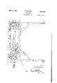
- Figure 1 is a front elevational view of a beam scale embodying my invention
- Figure 2 is a cross sectional View taken on line 2-2 of Figure 1;
- Figure 3 is a cross sectional view taken on the 101 line 3--3 of Figure 1;
- Figure 4 is a cross sectional view taken on line 4-4 of Figure 1;
- Figure 5 is a cross sectional view taken on line 5-5 of Figure 1;
- Figure 6 is a perspective view of the fulcrum member shown in Figures 1 and 2;
- Figure '7 is a perspective view of the weight member 30 and its bracket.
- numeral 5 designates generally a scale case provided by the channel iron, end pieces 6 which are extended downwardly to provide supporting legs.
- Hori-v zontal channel irons 8, 1' respectively, provide the top and bottom walls of the scale case. which are hinged as at H to the top channel 8 serve to close the sides of the case from one end to a point adjacent the other end, as shown in Figure 1.
- the doors H) are adapted to be secured in closed position by means of hasps, Illa.
- the extended portion of the end Walls 6, which provide the legs are suitably braced by channels 9, which are connected to the bottom wall 1.
- Suitable feet 611 are secured to the lower ends of the leg-providing end wall members 6 and these feet are adapted to be bolted to a floor or other support so as to hold the structure in upright position.
- the partition I2 in the form of a channel having its ends secured to the flanges of the channels I, 8.
- This partition is provided with a substantially rectangular opening I21: and at either side of the lower portion of the latter are provided drilled holes receiving bolts 16 which secure a fulcrum member l4 against the partition 12 with the slot Me aligned with the opening l2a.
- the fulcrum member M provides the medial thickened portion plate-like portion of member I4 and provides the transversely bifurcated fulcrum portions l lo, which are adapted to receive the fulcrum pivot l5 of the scale beam ll as shown in Figure 1. Pins l5a serve to retain the fulcrum pivot 15 of 55 Doors in 25.
- the scale beam IT has its forward end provided with the indicating pointer Ila and the opposite end wall of the scale case carries the cooperating fixed target or pointer 18.
- a pair of duplicate frame-like members I! of generally rectangular form carry the glass panes Hid and are adapted to be secured by screws 25.? to the flanges of the channel members "i, 3 to overlie the margins of said rectangular opening 5a.
- the function of the glass pane-carrying frame-like members 19 is to exclude dust and dirt from the righthand end of the scale case while exposing the indicating pointer Ila of the scale beam and the stationary pointer of the target l8; and also to carry the legends lSa, i% which indicate Over and Under weight respectively.
- One bar llc which connects the top and bottom channel members 1, 8 is provided with the inwardly extending pins 2
- the frame-like members 89 preferably have their inner faces cut away inwardly from the outer edges to provide the endless shoulder Him which engages against inner edges of the rectangular opening 511 which is provided by the bars I90 and the adjacent portions of the channels 6, l, and 8.
- the poises 22, 25, respectively Slideably mounted on the scale beam I! at opposite sides of the partition l2 are the poises 22, 25, respectively, and these are adapted to be held in a set position by means of set screws 22a, 2511, respectively.
- the poise 22 is adapted to be set at a predetermined one of the weight-indicating scale beam graduations ill) for indicating a predetermined weight of material.
- the poise 25 cooperates with graduations He at the lefthand end of the beam I1 and serves as a counterpoise for making allowance for the weight of a wheel barrow, cart, truck, or the like, which may contain material to be weighed on the scale platform (not shown).
- the angular rod 23 At the lefthand end of the scale beam l1 ( Figure l)-there is provided the angular rod 23 whose flattened end is riveted to one side of the scale beam I! as indicated at 24.
- the angular rod 23 provides the threaded arm 23a exposed above the beam I! and extending in the direction of the partition !2.
- 'I'hr'eadedly mounted on the arm 23a is the balance ball 24 and there is provided the jam nut 24a for holding the balance ball 24 in a set position.
- the function of the balance ball 24 is to effect initial balance of the scale beam.
- the hanger 2B for the rod 2? which latter is designed for connection to the member which supports or receives the material to be weighed.
- This member may I! in the bifurcated fulcrum be a hopper receiving crushed stone cement or in fact any material from a suitable source of supply; or it may be connected in well known manner to scale platform.
- the present scale is intended for weighing predetermined fixed amounts and to indicate by the pointers Ila, I8 the approach to the predetermined fixed amount which is indicated by the position of the poise 22 on the scale beam I1.
- I am able touse scale beam pointer end llw as the moveable indicator and thus overcome the objections to the dial type indicator, while at the same time readily meeting any requirementfor indicator movement in relation to the set weight amount for which the scale is set.
- I provide the balance weight 30, shown in Figure 1, as threaded onto the lower threaded end 28a of a metal strap 28 which is riveted or otherwise se cured as at 29 to the scale beam I! at a point adjacent the fulcrum pivot IS.
- a jam nut 3i serves to lock the indicating balance weight 30 in set position.
- the case 5 or its support which may be the legs 6 or a dispensing hopper apparatus with which the scale case is associated is set in substantially level position.
- both of the poises 22, 25 are set at the zero point of their scale graduations I'Ib, l'lc.
- the balance ball 24 is adjusted on the threaded shank 23a of rod 23 until the pointer Ila accurately registers with the target l8. Then the jam nut 24a is tightened up to hold the balance ball 24 in the set position.
- the scale is now ready for use and the poise 22 is set for the predetermined weight of the batches of material to be weighed.
- batches of 500 pounds of concrete aggregate are to be weighed; and furthermore that the State requirement is that the pointer of the indicator 11a in my apparatus -must move of an inch for the last five pounds of weight under or over the set weight amount.
- a balance weight 30 of proper size is selected and screwed onto the threaded end 28a of the metal strap 28. Then a five pound weight is placed in the hopper or upon the scale platform-neither shownwhich is connected to the rod 21.
- the doors I!) serve to exclude dirt from the scale case 5, leaving exposed only the pointer Ila and the target l8 through the glass panes l9d.
- bars He may be replaced by a slotted channel similar to partition (2. Such arrangement would further promote the exclusion of dust from the fulcrum [6 within case 5.
- balance weight 30 will be selected, applied and fixedly set at the factory to meet a customers requirements.
- a case supporting standards therefor, a partition extending transversely of the case adjacent one end portion thereof, said partition being vertically slotted, a block secured to one face of said partition and slotted to correspond, a bearing bracket carried by said block at each side of the slot and extending in the direction of the farther end of the case, a scale beam fulcrurned in said bearing brackets and oscillatable vertically through said partition slot, a weight fixed on said beam between its fulcrum point and the end farthest therefrom, said weight being adjustable toward and away from said beam, load supporting means on the beam at the opposite side of its fulcrum, and a variable poise on said beam at each side of its fulcrum.
Landscapes
- Physics & Mathematics (AREA)
- General Physics & Mathematics (AREA)
- Preparation Of Clay, And Manufacture Of Mixtures Containing Clay Or Cement (AREA)
Description
21, 1940.. J. H. GWYNNE BEAM SCALE Filed June 2, 1937 2 Sheets-Sheet 1 May 21, 1940. J. H. GWYNNE BEAM SCALE 2 Sheets-Sheet 2 Filed June 2, 1937 F v 1 W i 1 J j 4 5 l 2 4 A a 6 H j M; 2 JVI I lrlui- I 'm M I V.
Patented May 21, 1940 UNITED STATES PATENT OFFICE 1 Claim.
My invention relates to improvements in beam scales for weighing predetermined quantities of bulk material such as concrete aggregates, cement, grain, flour and the like.
A scale of this type has a considerable field of utility in connection with the mixing of concrete for construction work. The essential requirement of such a scale is that it shall readily indi cate predetermined weights of the sand, cement, etc., and also the approach to such weights. Heretofore scales of this class have required the use of a dial and pointer indicator and a common specification of the various State highway departments is that the even balance indicator must move a definite, and relatively small distance for the last unit of weight under or over even balance that is placed upon the scale platform or in the associated hopper, whichever happens to be used. For instance, when weighing batches of say 500 pounds, it might be required that the indicator pointer move of an inch for the last five pounds of weight under or over even balance. Heretofore it has not been considered practical to dispense with the dial type indicator and pointer despite the fact that same has proven objectionable, owing to extreme delicacy, lack of portability, expense, and lack of dependability due to sensitivity to friction caused by rust and dirt and for other reasons.
The primary object of my invention is. to
More specifically, it is the object of the invention to provide in combination with a beam of a scale a balance weight which is adapted to progressively resist swinging of the scale beam as the latter rocks toward the balanced position.
The invention also resides in certain novel features of construction, combination and arrangement of various parts, and in modes of operation, all of which will be readily apparent to those skilled in the art with reference to the accompanying drawings in connection with the detailed description to follow.
It is understood that the drawings illustrate what now appears to be a preferred example of the invention. However, it will be obvious that the inventive concept is susceptible of other mechanical expression within the spirit and scope of the subject matter claimed hereinafter.
In the drawings, wherein the same reference characters have been used to designate the same parts throughout the several views: 5
Figure 1 is a front elevational view of a beam scale embodying my invention;
Figure 2 is a cross sectional View taken on line 2-2 of Figure 1;
Figure 3 is a cross sectional view taken on the 101 line 3--3 of Figure 1;
Figure 4 is a cross sectional view taken on line 4-4 of Figure 1;
Figure 5 is a cross sectional view taken on line 5-5 of Figure 1;
Figure 6 is a perspective view of the fulcrum member shown in Figures 1 and 2; and
Figure '7 is a perspective view of the weight member 30 and its bracket.
Referring specifically to the drawings, numeral 5 designates generally a scale case provided by the channel iron, end pieces 6 which are extended downwardly to provide supporting legs. Hori-v zontal channel irons 8, 1' respectively, provide the top and bottom walls of the scale case. which are hinged as at H to the top channel 8 serve to close the sides of the case from one end to a point adjacent the other end, as shown in Figure 1. The doors H) are adapted to be secured in closed position by means of hasps, Illa. The extended portion of the end Walls 6, which provide the legs are suitably braced by channels 9, which are connected to the bottom wall 1. Suitable feet 611 are secured to the lower ends of the leg-providing end wall members 6 and these feet are adapted to be bolted to a floor or other support so as to hold the structure in upright position.
At a point inwardly spaced from the firstmentioned end of the case 5, there is provided the partition I2 in the form of a channel having its ends secured to the flanges of the channels I, 8. This partition is provided with a substantially rectangular opening I21: and at either side of the lower portion of the latter are provided drilled holes receiving bolts 16 which secure a fulcrum member l4 against the partition 12 with the slot Me aligned with the opening l2a. The fulcrum member M provides the medial thickened portion plate-like portion of member I4 and provides the transversely bifurcated fulcrum portions l lo, which are adapted to receive the fulcrum pivot l5 of the scale beam ll as shown in Figure 1. Pins l5a serve to retain the fulcrum pivot 15 of 55 Doors in 25.
Ma extending forwardly of the the scale beams arms I 4b.
The scale beam IT has its forward end provided with the indicating pointer Ila and the opposite end wall of the scale case carries the cooperating fixed target or pointer 18.
Reference has hereinbefore been made to the fact that the doors it! leave exposed the righthand end of the scale case. At the site of the last-mentioned ends of the doors I!) there are provided bars [90 connecting corresponding flanges of the top and bottom walls I, 8. These bars llc will be secured to the inner surfaces of the adjacent side flanges of the channels i, 8 and cooperate with the channel members 6, i, 8 to provide a rectangular opening 5a at each side of the scale case at the righthand end thereof as viewed in Figure 1.
A pair of duplicate frame-like members I!) of generally rectangular form carry the glass panes Hid and are adapted to be secured by screws 25.? to the flanges of the channel members "i, 3 to overlie the margins of said rectangular opening 5a. The function of the glass pane-carrying frame-like members 19 is to exclude dust and dirt from the righthand end of the scale case while exposing the indicating pointer Ila of the scale beam and the stationary pointer of the target l8; and also to carry the legends lSa, i% which indicate Over and Under weight respectively.
One bar llc which connects the top and bottom channel members 1, 8 is provided with the inwardly extending pins 2|, which are adapted to intercept the scale beam I1 and limit its swinging movement. These pins 2| will preferably be covered with rubber sleeves 21a for the purpose of absorbing the shock of impact of the scale beam IT. The frame-like members 89 preferably have their inner faces cut away inwardly from the outer edges to provide the endless shoulder Him which engages against inner edges of the rectangular opening 511 which is provided by the bars I90 and the adjacent portions of the channels 6, l, and 8.
Slideably mounted on the scale beam I! at opposite sides of the partition l2 are the poises 22, 25, respectively, and these are adapted to be held in a set position by means of set screws 22a, 2511, respectively. The poise 22 is adapted to be set at a predetermined one of the weight-indicating scale beam graduations ill) for indicating a predetermined weight of material. The poise 25 cooperates with graduations He at the lefthand end of the beam I1 and serves as a counterpoise for making allowance for the weight of a wheel barrow, cart, truck, or the like, which may contain material to be weighed on the scale platform (not shown).
At the lefthand end of the scale beam l1 (Figure l)-there is provided the angular rod 23 whose flattened end is riveted to one side of the scale beam I! as indicated at 24. The angular rod 23 provides the threaded arm 23a exposed above the beam I! and extending in the direction of the partition !2. 'I'hr'eadedly mounted on the arm 23a is the balance ball 24 and there is provided the jam nut 24a for holding the balance ball 24 in a set position. The function of the balance ball 24 is to effect initial balance of the scale beam.
Pivoted to the scale beam l1 adjacent and to the left of the partition 12 is the hanger 2B for the rod 2? which latter is designed for connection to the member which supports or receives the material to be weighed. This member may I! in the bifurcated fulcrum be a hopper receiving crushed stone cement or in fact any material from a suitable source of supply; or it may be connected in well known manner to scale platform.
As previously indicated, the present scale is intended for weighing predetermined fixed amounts and to indicate by the pointers Ila, I8 the approach to the predetermined fixed amount which is indicated by the position of the poise 22 on the scale beam I1.
Most states require that the indicators of scales of this character shall move a predetermined distance for the last unit of weight under or over the certain set amount for which scales of this kind are set. Such required indicator movement distances are relatively small when the set weight amount is small and proportionately higher when the set weight is higher. Considerable difiiculty has been experienced by manufacturers in meeting the required range of indicator movement with a dial type indicator and same is open to the objections heretofore noted.
I am able touse scale beam pointer end llw as the moveable indicator and thus overcome the objections to the dial type indicator, while at the same time readily meeting any requirementfor indicator movement in relation to the set weight amount for which the scale is set. In carrying out this phase of the invention I provide the balance weight 30, shown in Figure 1, as threaded onto the lower threaded end 28a of a metal strap 28 which is riveted or otherwise se cured as at 29 to the scale beam I! at a point adjacent the fulcrum pivot IS. A jam nut 3i serves to lock the indicating balance weight 30 in set position.
By way of summary the operation of the scale is explained as follows:
First, the case 5 or its support, which may be the legs 6 or a dispensing hopper apparatus with which the scale case is associated is set in substantially level position. Next, both of the poises 22, 25 are set at the zero point of their scale graduations I'Ib, l'lc. Following this, the balance ball 24 is adjusted on the threaded shank 23a of rod 23 until the pointer Ila accurately registers with the target l8. Then the jam nut 24a is tightened up to hold the balance ball 24 in the set position.
The scale is now ready for use and the poise 22 is set for the predetermined weight of the batches of material to be weighed. For the purpose of illustration, it will be assumed that batches of 500 pounds of concrete aggregate are to be weighed; and furthermore that the State requirement is that the pointer of the indicator 11a in my apparatus -must move of an inch for the last five pounds of weight under or over the set weight amount. In order to arrive at this adjustment, a balance weight 30 of proper size is selected and screwed onto the threaded end 28a of the metal strap 28. Then a five pound weight is placed in the hopper or upon the scale platform-neither shownwhich is connected to the rod 21. The distance that pointer Il'a moves under the action of such given pound weight is then noted and if such distance is greater" or less than A; of an inch, correction can be made by adjusting the balance weight 30 up or down on the threaded portion 28a of strap 28. The further the weight 30: is from the beam H, the shorter will be the distance that pointer I la will move under the influence of a given weight attached to rod 21. This is true because strap 28 is fixedly attached to scale beam I! in advance of fulcrum pivot if), from which it follows that the further beam ll swings upwardly the greater will be the distance from weight 30 to fulcrum pivot l5. It is therefore not necessary that the selected weight 30 be exactly of the size required to restrict pointer Ila to a certainlength of movement for each unit of weight carried by rod 21 as would be the case if weight 30 was not adjustable on portion 28a of strap "Z8.
When the scale is incorporated in a hopper type apparatus it would not be necessary to adjust the poise 25. But on the other hand, if rod 21 has connection with a platform and the material to be weighed is contained in cans, wheel barrows, or the like, allowance for the weight of such containers would have to be made. This is ac complished in obvious manner by simply disposing an empty container on such platform and then by movement of the poise 25 restoring the pointer Ila. to alignment with target l8.
When the scale is incorporated in a hopper type weighing apparatus the operator would simply observe the approach of pointer Ha, to alignment with the target l8 and would cut off the flow of material into the hopper at the proper time.
When material is being weighed in containers the operator would simply add or remove the material from the container until the pointer Ha registers with target I8.
The doors I!) serve to exclude dirt from the scale case 5, leaving exposed only the pointer Ila and the target l8 through the glass panes l9d.
A scale of this construction will obviously stand very hard usage as it comprehends no delicate parts. Furthermore, it embodies no parts which will be adversely affected by rust or dirt.
It might be mentioned further that bars He may be replaced by a slotted channel similar to partition (2. Such arrangement would further promote the exclusion of dust from the fulcrum [6 within case 5.
In many cases the balance weight 30 will be selected, applied and fixedly set at the factory to meet a customers requirements.
As stated earlier herein the particular details of construction shown and described can be varied and changed materially without departing from the spirit and scope of the invention. This applies especially to the location of the balance weight 36, and the pointer and target Ha, l8.
Having thus described my invention, what I claim as new is:
In a beam scale, a case, supporting standards therefor, a partition extending transversely of the case adjacent one end portion thereof, said partition being vertically slotted, a block secured to one face of said partition and slotted to correspond, a bearing bracket carried by said block at each side of the slot and extending in the direction of the farther end of the case, a scale beam fulcrurned in said bearing brackets and oscillatable vertically through said partition slot, a weight fixed on said beam between its fulcrum point and the end farthest therefrom, said weight being adjustable toward and away from said beam, load supporting means on the beam at the opposite side of its fulcrum, and a variable poise on said beam at each side of its fulcrum.
JOSEPH H. GWYNNE.
Priority Applications (1)
| Application Number | Priority Date | Filing Date | Title |
|---|---|---|---|
| US146061A US2201291A (en) | 1937-06-02 | 1937-06-02 | Beam scale |
Applications Claiming Priority (1)
| Application Number | Priority Date | Filing Date | Title |
|---|---|---|---|
| US146061A US2201291A (en) | 1937-06-02 | 1937-06-02 | Beam scale |
Publications (1)
| Publication Number | Publication Date |
|---|---|
| US2201291A true US2201291A (en) | 1940-05-21 |
Family
ID=22515700
Family Applications (1)
| Application Number | Title | Priority Date | Filing Date |
|---|---|---|---|
| US146061A Expired - Lifetime US2201291A (en) | 1937-06-02 | 1937-06-02 | Beam scale |
Country Status (1)
| Country | Link |
|---|---|
| US (1) | US2201291A (en) |
-
1937
- 1937-06-02 US US146061A patent/US2201291A/en not_active Expired - Lifetime
Similar Documents
| Publication | Publication Date | Title |
|---|---|---|
| US2201291A (en) | Beam scale | |
| US2346882A (en) | Net and gross weigher | |
| US2467300A (en) | Weighing apparatus | |
| US2316947A (en) | Weighing scale | |
| US2009020A (en) | Scale | |
| US2013957A (en) | Weighing scale | |
| US2282052A (en) | Testing device for determining mass distribution | |
| US3093203A (en) | Container filling apparatus | |
| US2659593A (en) | Weighing scale | |
| US3396A (en) | Balance | |
| US2031439A (en) | Weighing scale | |
| US2576468A (en) | Weighing scale for determining mass distributions | |
| US1853206A (en) | Scale | |
| US2642277A (en) | Weighing scale | |
| US1715832A (en) | Clarence h | |
| US3174568A (en) | Weighing scale having cone pivots and concavity bearing surfaces | |
| US2049281A (en) | Weighing device | |
| US3075597A (en) | Torsion balance having mechanically amplified indicator | |
| US1943651A (en) | Health scale | |
| US1005942A (en) | Scale. | |
| US1656435A (en) | Weighing scale | |
| US1994549A (en) | Counting scale | |
| US1072018A (en) | Scale. | |
| US2591034A (en) | Mixing scale | |
| US1564845A (en) | Counting scale |