US220124A - Improvement in locks - Google Patents
Improvement in locks Download PDFInfo
- Publication number
- US220124A US220124A US220124DA US220124A US 220124 A US220124 A US 220124A US 220124D A US220124D A US 220124DA US 220124 A US220124 A US 220124A
- Authority
- US
- United States
- Prior art keywords
- lock
- shackle
- disk
- tumblers
- tumbler
- Prior art date
- Legal status (The legal status is an assumption and is not a legal conclusion. Google has not performed a legal analysis and makes no representation as to the accuracy of the status listed.)
- Expired - Lifetime
Links
- 230000002093 peripheral effect Effects 0.000 description 3
- XLYOFNOQVPJJNP-UHFFFAOYSA-N water Substances O XLYOFNOQVPJJNP-UHFFFAOYSA-N 0.000 description 3
- 238000010276 construction Methods 0.000 description 2
- 230000000284 resting effect Effects 0.000 description 2
- 208000027418 Wounds and injury Diseases 0.000 description 1
- 230000015572 biosynthetic process Effects 0.000 description 1
- 230000006378 damage Effects 0.000 description 1
- 208000014674 injury Diseases 0.000 description 1
- 238000003780 insertion Methods 0.000 description 1
- 230000037431 insertion Effects 0.000 description 1
- 239000007787 solid Substances 0.000 description 1
Images


Classifications
-
- E—FIXED CONSTRUCTIONS
- E05—LOCKS; KEYS; WINDOW OR DOOR FITTINGS; SAFES
- E05B—LOCKS; ACCESSORIES THEREFOR; HANDCUFFS
- E05B39/00—Locks giving indication of authorised or unauthorised unlocking
- E05B39/04—Locks giving indication of authorised or unauthorised unlocking with counting or registering devices
-
- Y—GENERAL TAGGING OF NEW TECHNOLOGICAL DEVELOPMENTS; GENERAL TAGGING OF CROSS-SECTIONAL TECHNOLOGIES SPANNING OVER SEVERAL SECTIONS OF THE IPC; TECHNICAL SUBJECTS COVERED BY FORMER USPC CROSS-REFERENCE ART COLLECTIONS [XRACs] AND DIGESTS
- Y10—TECHNICAL SUBJECTS COVERED BY FORMER USPC
- Y10T—TECHNICAL SUBJECTS COVERED BY FORMER US CLASSIFICATION
- Y10T70/00—Locks
- Y10T70/40—Portable
- Y10T70/413—Padlocks
- Y10T70/437—Key-controlled
- Y10T70/439—Non-shackle type
- Y10T70/441—Housing extension and cooperating detent
-
- Y—GENERAL TAGGING OF NEW TECHNOLOGICAL DEVELOPMENTS; GENERAL TAGGING OF CROSS-SECTIONAL TECHNOLOGIES SPANNING OVER SEVERAL SECTIONS OF THE IPC; TECHNICAL SUBJECTS COVERED BY FORMER USPC CROSS-REFERENCE ART COLLECTIONS [XRACs] AND DIGESTS
- Y10—TECHNICAL SUBJECTS COVERED BY FORMER USPC
- Y10T—TECHNICAL SUBJECTS COVERED BY FORMER US CLASSIFICATION
- Y10T70/00—Locks
- Y10T70/70—Operating mechanism
- Y10T70/7441—Key
- Y10T70/7915—Tampering prevention or attack defeating
- Y10T70/7932—Anti-pick
- Y10T70/7944—Guard tumbler
-
- Y—GENERAL TAGGING OF NEW TECHNOLOGICAL DEVELOPMENTS; GENERAL TAGGING OF CROSS-SECTIONAL TECHNOLOGIES SPANNING OVER SEVERAL SECTIONS OF THE IPC; TECHNICAL SUBJECTS COVERED BY FORMER USPC CROSS-REFERENCE ART COLLECTIONS [XRACs] AND DIGESTS
- Y10—TECHNICAL SUBJECTS COVERED BY FORMER USPC
- Y10T—TECHNICAL SUBJECTS COVERED BY FORMER US CLASSIFICATION
- Y10T70/00—Locks
- Y10T70/80—Parts, attachments, accessories and adjuncts
- Y10T70/8027—Condition indicators
- Y10T70/8135—With register
- Y10T70/8162—Padlock
Definitions
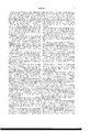
- FIG. 1 is a perspective view of my improved lock, the dotted lines indicating the position of the shackle when opened, and the fulllines the position of the same when closed.
- Fig. 2 is a like view of the registering mechanism separated from the casin
- Fig. 3 is a plan view of one of the register-dials and its engaging-wheel.
- Fig. 5 is a like view of said lock, the shackle being unlocked and open.
- Fig. 7 is a central longitudinal section of the same.
- Fig. 8 is a horizontal section upon line or a: of Fi 4
- Fig. 9 is a central longitudinal section of the inner end of the key.
- The-design of my invention is, mainly, to render a lock more secure against picking, and, further, to increase its simplicity and durability; to which end it consists, principally, in a padlock having a pivoted shackle which has the same axial center as the key and the tumbler-moving mechanism, and movesin a plane having a right angle to the body of the lock, substantially as and for the purpose hereinafter specified.
- a lock provided with a revolving shackle, and having a circular curb formed upon and extending from the casing, around the pivotal opening of said shackle, upward into a eorrespondii'lg recess formed within the contiguous portion of the latter, substantially as and for the purpose hereinafter shown and described.
- a registering-lock provided with a pivoted shackle which rotates in a plane having a right angle to the body of the lock, and furnishes an axial hearing for and upon which are placed registeringdisks, substantially as and for the purpose hereinafter specified.
- A represents the casing of my lock, which has, preferably, the form of two cylinders, united at their sides, and at one end is permanently closed, while at its opposite upper end said casing may be provided upon its inner corner with a rabbet, a, that is slightly undercut, so as to give greaterhorizontal depth at its lower side, as shown in Figs. 4 and 5.
- a head, B which at its edge corresponds to and fits into the same, or into the rabhet a, when one is provided, and is secured in place by compressing the upper end of said casing until it embraces the edge of said head closely.
- a cylindrical flange 1
- b 1
- b 1
- an opening, 1) within which is fitted a tube, 0, that extends downward through and closely fills an opening, a that is providedin the lower end of the casing A, the said end of said tube being flush with the lower surface of said casing.
- a curved bar, 0, which, when turned to the position shown in Fi 1, coincides with a similarly-curved bar, B, that is formed upon the head B, and, in connection with said bar B, forms a shackle of usual form.
- the base of said bar is extended adially, so as to form a shoulder, c, thatbears upon theupper side of the head B, and a cylindrical block, D, is titted over said tube 0 within the flange b, where it is held in place, with its upper end bearing lightly against the lower face of the head B by means of a set-screw, d, which passes radially inward through said block and into said tube.
- a vertical curb, b is provided around the upper end of the opening b and within the lower side of the shoulder c is formed a corresponding recess, 0, that receives said curb, as shown in Figs. 4 and 5, the joint of the latter being sufficiently elevated above the upper surface of the head B to prevent water from passing over, even when said water is driven by the wind.
- the tube or shackle-shank O is locked in position by means of mechanism similar to that which is used in the Yale locks, the construction of which is as follows: Within the upper portion of the tube 0, and within the block D, are provided a number of round openings, (1, which pass radially outward in a line with the plane of the shackle C, and are relatively arranged in aline with the axis of said tube. ithin the block I) of the head B are provided openings b which correspond to and form continuations of the openings d, when the pivoted portion of the shackle O is caused to coincide with the fixed port-ion B, as seen in Fig.
- a pin or tumbler, E placed within and caused to loosely fill each of said openings (1, may be moved longitudinally within the same and its coinciding opening b
- the tumblers E have each such length as to cause them to extend from the side of the tube opposite to the openings (1 out-ward into the openings If, and are each held in such position by means of a spiral spring, F, which is placed within each opening b with one of its ends bearing upon the casin g A and its opposite end bearin g against the outer end of said tumblers, as
- Each tumbler E is divided transversely into two sections, which have unequal lengths, and, with exception of the enter one, said tumblers have their points of division entirely within the block D,
- the outward movement of the tumblers E is effected by means of a key, G, which is fitted into the tube or shank C, and is provided upon one side with a longitudinal groove, 9, that has such conformation of its bottom as to cause it, when in place within said tube, to raise each tumbler to the exact position necessary in order that its line of division may coincide with the periphery of the block D, as shown by the dotted lines of Fi 4.
- the tumbler E does not operate to lock the shackle-shank except when moved outward from its normal position, and that before any manipulations of the lockingtumblers E can be had said guard-tumbler must be moved outward, in which position the latter will so effectually hold said shackleshank in position as to prevent the operator from determining when each locking-tumbler reaches the point of release.
- the key G has its groove 9 cut entirely through at the point which comes opposite to the inner end of the guard-tumbler E, so that when said key is placed within the lock said tumbler is first raised, and then permitted to drop to its normal position, with its inner end resting upon the side of the key-opening, as
- a number of disks, H Upon the tube or shank G are journaled a number of disks, H, each of which is provided with ten radial notches, h, that are arranged at equidistant points around its periphery.
- a second and smaller disk, H is secured to one side of said disk H, and is separated therefrom, near its outer edge, by a space somewhat wider than the thickness of said disk H.
- the disk H is provided with one radial notch, h, which coincides with one of the notches h of the disk H, while at a point midway between said notch h and the next forward notch h of said disk H is placed a pin, 70?, that extends between and has its ends socured within said disks.
- each of said wheels has six peripheral teeth, 1', that have a forward inclination, and midway between each of said teeth is provided a pin or stud, 2 that extends laterally outward in a line with the axis of said wheel.
- each wheel I is such as to cause its teeth to engage with the pin 71?, while its studs t" are placed at such points, radially, as to cause two of them to bear upon the periphery of one of the disks H, while their ends extend into two of the notches h of the disk H next in front, and thus lock said wheel and disks in position.
- a disk, H Secured upon the outer end of the shackleshank (J, and rotating with the same, is a disk, H which is in all respects like the disks H is provided with a peripheral notch, 7L1, and pin ]L2, and performs the same office, but is not attached to a disk, H.
- Each of the disks H has ten peripheral n umbers, from 1 to 0, both inclusive, and by means of a glazed opening, a formed in one side of the casing A, the numbers in line therewith upon each disk or dial can be seen, said numbers being so arranged as to be read in a line from the lower end of said casing upward.
- the construction of the registering mechanism is such as to prevent motion in a rearward direction, so that it is impossible to turn back and falsify the register, while it is equally impossible that any of the indicator-disks should be moved forward out of its order, or with any greater relative speed than one revolution to ten revolutions of the next preceding disk.
- the tenth notch his omitted from the last disk H by which means the further movement of said disk and the preceding disks is arrested one number before the maximum, and no further motion in either direction is possible without breakage until the lock has been taken apart and said mechanism readjusted.
- the first dial H is somewhat thicker than the remaining dials, so as to enable larger figures to be placed upon its periphery, and has but five figures, which are arranged at equidistant points.
- the disk H is provided with two pins, h", and at each revolution moves the wheel I forward two teeth, so as to cause one of the five figures of the disk-dial H to appear through the opening a at each complete revolution.
- Said opening should be divided by a cross-bar, so as to separate the figures of the first dial from those which follow the same.
- the letter-carrier in opening and closing the letter-box for the first time each day, causes the figure 2 to appear on the first dial, which, by appropriate lettering on the casing, indicates that the first collection has been made, and at each succeeding collection causes the appropriatenumeral to appear, by which means any person intrusted may know what collections have been made and what number yet remains.
- the numerals upon the collection-dial should be increased and the mechanism changed, as will be obvious, so as to cause the same to successively appear at each revolution of the shackle-spindle; but if the number of collections does not equal the number of the said numerals, then the carrier at the time of the last collection would turn the shackle-spindle until the figure 1 appears, when the lock is ready for the next days operations.
- the numeral space'next preceding the figure 1 may be left blank, so that until the first collection has been made each day no number will appear in sight upon the collection-dial, and the appearanceof a numeral would indicate that the number of collection represented thereby had been made.
- a padlock having a pivoted shackle which has the same axial center as the key and the tumbler-movin g mechanism and moves in a plane having a right angle to the body of the lock, substantially as and for the purpose specified.
- a guard-tumbler arranged in front of the remaining tumblers, and having such lateral dimensions as to conceal from view the same, substantially as and for the purpose shown.
- a guard-tumbler placed in front of the remaining tumblers, and having its inner end in contact with or close proximity to the inner side of the key-hole when in position to permit the locking mechanism to be operated, substantially as and for the purpose set forth.
- a circular curb formed upon the easin g, and extending upward around the pivotal opening for said shackle, in combination with a corresponding recess formed within the contiguous superimposed portion of said shackle, substantially as and for the purpose shown and described.
- a registering-lock provided with a pivoted shackle which rotates in a plane having a right angle to the body of the lock, and furnishes an axial bearing for and upon which are placed registering-disks, substantially as and for the purpose specified.
- a key having a radial opening within its body, through which one of said tumblers may drop to its normal position after said key has been inserted within the lock, substantially as and for the purpose shown.
Landscapes
- Lock And Its Accessories (AREA)
Description
2 Sheets-Sheet 1. H. CLARKE.
v Look.
No. 220,124. Patented Sept. 30,1879.
r ll
N. PETERS. PHOTO-LITHOGHAFHER, WASHiNGTON. n C.
2- Sheet s-Sheet 2.
H. CLARKE.
Look.
Patented Sept. 30,1879.
gig??? a a a MPETERS, PNoTo LITHOGRAPHER WASHNGTON D C UNITED STATES PATENT ()FFICE.
HENRY CLARKE, OF BALTIMORE, MARYLAND.
IMPROVEMENT IN LOCKS.
Specification forming part of Letters Patent No. 220,! 24,- dated September 30, 1879; application filed February 10, 1879.
To all whom it may concern:
Be it known that I, HENRY CLARKE, of Baltimore, in the county of Baltimore, and in the State of Maryland, have invented certain new and useful Improvements in Locks; and do hereby declare that the following is a full, clear, and exact description thereof, reference being had to the accompanying drawings, making a part of this specification, in which Figure 1 is a perspective view of my improved lock, the dotted lines indicating the position of the shackle when opened, and the fulllines the position of the same when closed. Fig. 2 is a like view of the registering mechanism separated from the casin Fig. 3 is a plan view of one of the register-dials and its engaging-wheel. Fig. 4. is a central longitudinal section of the lock, showing the positions of parts when the shackle is closed and locked. Fig. 5 is a like view of said lock, the shackle being unlocked and open. Fig. (iis aperspective view of the head of the casing separated from the lock. Fig. 7 is a central longitudinal section of the same. Fig. 8 is a horizontal section upon line or a: of Fi 4, and Fig. 9 is a central longitudinal section of the inner end of the key. I
Letters of like name and kind refer to like parts in each of the figures.
The-design of my invention is, mainly, to render a lock more secure against picking, and, further, to increase its simplicity and durability; to which end it consists, principally, in a padlock having a pivoted shackle which has the same axial center as the key and the tumbler-moving mechanism, and movesin a plane having a right angle to the body of the lock, substantially as and for the purpose hereinafter specified.
It consists, further, in combining, with a lock provided with radially-moving pin-tumblers, a guard-tumbler arranged in front of the remaining tumblers, and having such lateral dimensions as to conceal from view the remaining tumblers, substantially as and for the purpose hereinafter shown.
It consists, further, in combining, with a lock provided with radially-moving pin-tumblers, a guard-tun'ibler placed in front of the remaining tumblers, and having its inner end in contact with or close proximity to the inner side of the key-hole when in position to permit the locking mechanism to be operated, substantially as and for the purpose hereinafter set forth.
It consists, further, in a lock provided with a revolving shackle, and having a circular curb formed upon and extending from the casing, around the pivotal opening of said shackle, upward into a eorrespondii'lg recess formed within the contiguous portion of the latter, substantially as and for the purpose hereinafter shown and described.
It consists, further, in a registering-lock provided with a pivoted shackle which rotates in a plane having a right angle to the body of the lock, and furnishes an axial hearing for and upon which are placed registeringdisks, substantially as and for the purpose hereinafter specified.
It consists, finally, in combining, with alock provided with radially-moving pin-tumblers, a key having a radial opening within its body, through which one of said tumblers may drop to its normal position after said key has been inserted within the lock, substantially as and for the purpose hereinafter shown.
In the annexed drawings, A represents the casing of my lock, which has, preferably, the form of two cylinders, united at their sides, and at one end is permanently closed, while at its opposite upper end said casing may be provided upon its inner corner with a rabbet, a, that is slightly undercut, so as to give greaterhorizontal depth at its lower side, as shown in Figs. 4 and 5.
Within the upper end of the casin 'Ais fitted a head, B, which at its edge corresponds to and fits into the same, or into the rabhet a, when one is provided, and is secured in place by compressing the upper end of said casing until it embraces the edge of said head closely.
From the lower side of the head B, at one side of its longitudinal center, a cylindrical flange, 1), projects downward about one-half an inch, while from the other portion of said head a rectangular block, b extends downward to the lower end of said flange, and from its lower end a round bar, 12 projects downward to the lower end of the casing A.
At the axis of the cylindrical flange l) is provided, within the head 13, an opening, 1), within which is fitted a tube, 0, that extends downward through and closely fills an opening, a that is providedin the lower end of the casing A, the said end of said tube being flush with the lower surface of said casing.
Upon the upper end of the tube 0 is provided a curved bar, 0, which, when turned to the position shown in Fi 1, coincides with a similarly-curved bar, B, that is formed upon the head B, and, in connection with said bar B, forms a shackle of usual form.
In consequence of the formation of the part 0 upon the journaled tube 0, the rotation of the latter will cause the former to move away from the part B, as seen in Fig. 5, so as to permit of the insertion within the shackle of a ring, staple, &c., after which, by turning said part 0 to its normal position, the part inserted within said shackle will be locked in place.
In order that the tube 0 and its shackle-bar C may be held in longitudinal position while free to rotate within the head B and casin g A, the base of said bar is extended adially, so as to form a shoulder, c, thatbears upon theupper side of the head B, and a cylindrical block, D, is titted over said tube 0 within the flange b, where it is held in place, with its upper end bearing lightly against the lower face of the head B by means of a set-screw, d, which passes radially inward through said block and into said tube.
To prevent water from passing into the easing A around the upper end of the tube (1, a vertical curb, b, is provided around the upper end of the opening b and within the lower side of the shoulder c is formed a corresponding recess, 0, that receives said curb, as shown in Figs. 4 and 5, the joint of the latter being sufficiently elevated above the upper surface of the head B to prevent water from passing over, even when said water is driven by the wind.
The tube or shackle-shank O is locked in position by means of mechanism similar to that which is used in the Yale locks, the construction of which is as follows: Within the upper portion of the tube 0, and within the block D, are provided a number of round openings, (1, which pass radially outward in a line with the plane of the shackle C, and are relatively arranged in aline with the axis of said tube. ithin the block I) of the head B are provided openings b which correspond to and form continuations of the openings d, when the pivoted portion of the shackle O is caused to coincide with the fixed port-ion B, as seen in Fig. 4, in which position a pin or tumbler, E, placed within and caused to loosely fill each of said openings (1, may be moved longitudinally within the same and its coinciding opening b The tumblers E have each such length as to cause them to extend from the side of the tube opposite to the openings (1 out-ward into the openings If, and are each held in such position by means of a spiral spring, F, which is placed within each opening b with one of its ends bearing upon the casin g A and its opposite end bearin g against the outer end of said tumblers, as
shown in Fig. 4. Each tumbler E is divided transversely into two sections, which have unequal lengths, and, with exception of the enter one, said tumblers have their points of division entirely within the block D,
As thus arranged, it will be seen that while the tumblers E occupy their normal positions they efi'ectually lock the tube or shackle-shank G in place, and prevent the same from rotating; but if said tumblers are raised until the line of division of each coincides with the periphery of the block D, said shank may then be rotated within each casing, while the outer sections of each tumbler will rest upon the surface of said block, as seen in Fig. 5, until the parts are restored again to the positions shown in Fig. at, when said outer sections will be moved inward by the springs F, and will press the said inner sections inward to place.
The outward movement of the tumblers E is effected by means of a key, G, which is fitted into the tube or shank C, and is provided upon one side with a longitudinal groove, 9, that has such conformation of its bottom as to cause it, when in place within said tube, to raise each tumbler to the exact position necessary in order that its line of division may coincide with the periphery of the block D, as shown by the dotted lines of Fi 4.
In order that unauthorized persons may not be enabled to tamper with the look by raising the tumblers E with instruments and ascertaining the point at which each ceases to lock the shank O, I place in front of the lockingtumblers a guard-tumbler, E, which has such diameter as to nearly till the axial or key opening within said shank, and has its line of division at such point as to cause the same to coincide with the periphery of the block 1) when said tumbler occupies its normal position, as seen in Fig. 4.
It will be seen that the tumbler E does not operate to lock the shackle-shank except when moved outward from its normal position, and that before any manipulations of the lockingtumblers E can be had said guard-tumbler must be moved outward, in which position the latter will so effectually hold said shackleshank in position as to prevent the operator from determining when each locking-tumbler reaches the point of release.
The key G has its groove 9 cut entirely through at the point which comes opposite to the inner end of the guard-tumbler E, so that when said key is placed within the lock said tumbler is first raised, and then permitted to drop to its normal position, with its inner end resting upon the side of the key-opening, as
seen in Fig. 4-.
In order that the opening of the lock may be recorded, so that any loss or injury resulting therefrom may be fixed upon the person having charge at the time such loss occurred, I employ the followingdescribcd mechanism, which is substantially the same as that shown in Letters Patent No.203,7t)7, which was issued to me upon the 14th day of May, 1878.
Upon the tube or shank G are journaled a number of disks, H, each of which is provided with ten radial notches, h, that are arranged at equidistant points around its periphery. A second and smaller disk, H, is secured to one side of said disk H, and is separated therefrom, near its outer edge, by a space somewhat wider than the thickness of said disk H.
The disk H is provided with one radial notch, h, which coincides with one of the notches h of the disk H, while at a point midway between said notch h and the next forward notch h of said disk H is placed a pin, 70?, that extends between and has its ends socured within said disks.
Journaled upon the bar I) is a series of wheels, I, which correspond in number to the number of the disks H, and have their edges contained within the spaces between each pair ofdisks HandH. Each of said wheels has six peripheral teeth, 1', that have a forward inclination, and midway between each of said teeth is provided a pin or stud, 2 that extends laterally outward in a line with the axis of said wheel.
The diameter of each wheel I is such as to cause its teeth to engage with the pin 71?, while its studs t" are placed at such points, radially, as to cause two of them to bear upon the periphery of one of the disks H, while their ends extend into two of the notches h of the disk H next in front, and thus lock said wheel and disks in position.
Secured upon the outer end of the shackleshank (J, and rotating with the same, is a disk, H which is in all respects like the disks H is provided with a peripheral notch, 7L1, and pin ]L2, and performs the same office, but is not attached to a disk, H. If, now, the shackleshank or spindle O is caused to rotate, at each revolution the pin h of the disk H will ongage with and move forward one tooth tof the contiguous wheel I, while at the same instant the notch h is brought opposite to the rear one of the studs 2', which is resting upon the periphery of said disk, and permits said wheel to turn freely until its next succeeding stud t" is arrested by contact with the solid portion of the periphery of said disk. This movement of said wheel I causes the first disk H, with which its studs are engaged, to be moved forward one-tenth of a revolution, such operation being repeated at each revolution of said shackle-shank C.
When the first disk H has made a complete revolution, it moves the second wheel I forward one tooth, and, by such movement, causes the second disk H to be rotated one-tenth of a revolution, said operation being repeated whenever each disk H makes a complete revolution. ,A
Each of the disks H has ten peripheral n umbers, from 1 to 0, both inclusive, and by means of a glazed opening, a formed in one side of the casing A, the numbers in line therewith upon each disk or dial can be seen, said numbers being so arranged as to be read in a line from the lower end of said casing upward.
The figures upon the first or lower disk indicate units, those of the second disk tens, the third hundreds, the fourth thousands, &c., so that the difference between the numbers shown before and after the shackle has been revolved will correctly indicate the number of such revolutions.
The construction of the registering mechanism is such as to prevent motion in a rearward direction, so that it is impossible to turn back and falsify the register, while it is equally impossible that any of the indicator-disks should be moved forward out of its order, or with any greater relative speed than one revolution to ten revolutions of the next preceding disk.
In order that the registering mechanism may not be operated beyond the maximum number, the tenth notch his omitted from the last disk H, by which means the further movement of said disk and the preceding disks is arrested one number before the maximum, and no further motion in either direction is possible without breakage until the lock has been taken apart and said mechanism readjusted.
hen the lock is required for use in securing street letter-boxcs, the foMowing-described change is made in the register, for the purpose of enabling the number of collections to be shown.
The first dial H is somewhat thicker than the remaining dials, so as to enable larger figures to be placed upon its periphery, and has but five figures, which are arranged at equidistant points.
The disk H is provided with two pins, h", and at each revolution moves the wheel I forward two teeth, so as to cause one of the five figures of the disk-dial H to appear through the opening a at each complete revolution. Said opening should be divided by a cross-bar, so as to separate the figures of the first dial from those which follow the same.
As thus arranged, the letter-carrier, in opening and closing the letter-box for the first time each day, causes the figure 2 to appear on the first dial, which, by appropriate lettering on the casing, indicates that the first collection has been made, and at each succeeding collection causes the appropriatenumeral to appear, by which means any person intrusted may know what collections have been made and what number yet remains.
If there are more than five collections made each day from any box, the numerals upon the collection-dial should be increased and the mechanism changed, as will be obvious, so as to cause the same to successively appear at each revolution of the shackle-spindle; but if the number of collections does not equal the number of the said numerals, then the carrier at the time of the last collection would turn the shackle-spindle until the figure 1 appears, when the lock is ready for the next days operations.
If desired, the numeral space'next preceding the figure 1 may be left blank, so that until the first collection has been made each day no number will appear in sight upon the collection-dial, and the appearanceof a numeral would indicate that the number of collection represented thereby had been made.
Each complete revolution of the collectiondial would cause the next succeeding dial to move forward one number, and thereby the latter would become the units-dial of the reg ister which indicated the number of daily collections made from the box to which the look was attached.
Having thus fully set forth the nature and merits of my invention, what I claim as new 1s 1. A padlock having a pivoted shackle which has the same axial center as the key and the tumbler-movin g mechanism and moves in a plane having a right angle to the body of the lock, substantially as and for the purpose specified.
2. In combination with alock' provided with radially-movin g pin-tumblers, a guard-tumbler arranged in front of the remaining tumblers, and having such lateral dimensions as to conceal from view the same, substantially as and for the purpose shown.
3. In combination with a lock provided with radially-moving pin-tumblers, a guard-tumbler placed in front of the remaining tumblers, and having its inner end in contact with or close proximity to the inner side of the key-hole when in position to permit the locking mechanism to be operated, substantially as and for the purpose set forth. 7
4. In a lock provided with a revolving shackle, a circular curb formed upon the easin g, and extending upward around the pivotal opening for said shackle, in combination with a corresponding recess formed within the contiguous superimposed portion of said shackle, substantially as and for the purpose shown and described.
5. A registering-lock provided with a pivoted shackle which rotates in a plane having a right angle to the body of the lock, and furnishes an axial bearing for and upon which are placed registering-disks, substantially as and for the purpose specified.
6. In combination with a lock provided with radially-moving pin-tumblers, a key having a radial opening within its body, through which one of said tumblers may drop to its normal position after said key has been inserted within the lock, substantially as and for the purpose shown.
In testimony that I claim the foregoing I have hereunto set my hand this 22d day of October, 1878.
HENRY CLARKE.
Witnesses:
JAS. E. HU'roIIrksoN, WILLIAM FITCH.
Publications (1)
| Publication Number | Publication Date |
|---|---|
| US220124A true US220124A (en) | 1879-09-30 |
Family
ID=2289525
Family Applications (1)
| Application Number | Title | Priority Date | Filing Date |
|---|---|---|---|
| US220124D Expired - Lifetime US220124A (en) | Improvement in locks |
Country Status (1)
| Country | Link |
|---|---|
| US (1) | US220124A (en) |
Cited By (3)
| Publication number | Priority date | Publication date | Assignee | Title |
|---|---|---|---|---|
| US8201423B1 (en) | 2003-08-05 | 2012-06-19 | The Eastern Company | Combination and key operated locks with indicators |
| USD674266S1 (en) | 2003-08-05 | 2013-01-15 | The Eastern Company | Cable shackle padlock having a sidewall aperture for a status indicator |
| US8881558B2 (en) | 2003-08-05 | 2014-11-11 | The Eastern Company | Combination and key operated locks with indicators |
-
0
- US US220124D patent/US220124A/en not_active Expired - Lifetime
Cited By (3)
| Publication number | Priority date | Publication date | Assignee | Title |
|---|---|---|---|---|
| US8201423B1 (en) | 2003-08-05 | 2012-06-19 | The Eastern Company | Combination and key operated locks with indicators |
| USD674266S1 (en) | 2003-08-05 | 2013-01-15 | The Eastern Company | Cable shackle padlock having a sidewall aperture for a status indicator |
| US8881558B2 (en) | 2003-08-05 | 2014-11-11 | The Eastern Company | Combination and key operated locks with indicators |
Similar Documents
| Publication | Publication Date | Title |
|---|---|---|
| US220124A (en) | Improvement in locks | |
| US274875A (en) | Indicator-lock | |
| US226069A (en) | hathaway | |
| US123558A (en) | Improvement in indicator-padlocks | |
| US439624A (en) | William fessenden beasley | |
| US1002356A (en) | Indicating-lock. | |
| US692538A (en) | Bicycle-lock. | |
| US499503A (en) | William f | |
| US499501A (en) | Indicator-lock | |
| US364467A (en) | Jacob baum | |
| US449314A (en) | Joseph m | |
| US344176A (en) | edgar | |
| US1156659A (en) | Dial for combination-locks. | |
| US1200949A (en) | Lock. | |
| US170889A (en) | Improvement in indicator-locks | |
| US232069A (en) | russell | |
| US439623A (en) | Seal-lock | |
| US458125A (en) | Joseph m | |
| US1136357A (en) | Combination-lock. | |
| US80637A (en) | Thomas-lalok | |
| US219495A (en) | Improvement in indicator-locks | |
| US200259A (en) | Improvement in registers | |
| US203707A (en) | Improvement in registers | |
| US1052686A (en) | Indicator. | |
| US287028A (en) | In dic ato r - pa d lo c k |