US2198910A - Mower attachment for tractors - Google Patents
Mower attachment for tractors Download PDFInfo
- Publication number
- US2198910A US2198910A US230638A US23063838A US2198910A US 2198910 A US2198910 A US 2198910A US 230638 A US230638 A US 230638A US 23063838 A US23063838 A US 23063838A US 2198910 A US2198910 A US 2198910A
- Authority
- US
- United States
- Prior art keywords
- frame
- bar
- shaft
- tractor
- cutter bar
- Prior art date
- Legal status (The legal status is an assumption and is not a legal conclusion. Google has not performed a legal analysis and makes no representation as to the accuracy of the status listed.)
- Expired - Lifetime
Links
- 230000008878 coupling Effects 0.000 description 2
- 238000010168 coupling process Methods 0.000 description 2
- 238000005859 coupling reaction Methods 0.000 description 2
- 101100102516 Clonostachys rogersoniana vern gene Proteins 0.000 description 1
- 241001236644 Lavinia Species 0.000 description 1
- 241001446467 Mama Species 0.000 description 1
- 230000005540 biological transmission Effects 0.000 description 1
- 210000005069 ears Anatomy 0.000 description 1
- 238000003466 welding Methods 0.000 description 1
Images


Classifications
-
- A—HUMAN NECESSITIES
- A01—AGRICULTURE; FORESTRY; ANIMAL HUSBANDRY; HUNTING; TRAPPING; FISHING
- A01D—HARVESTING; MOWING
- A01D34/00—Mowers; Mowing apparatus of harvesters
- A01D34/01—Mowers; Mowing apparatus of harvesters characterised by features relating to the type of cutting apparatus
- A01D34/02—Mowers; Mowing apparatus of harvesters characterised by features relating to the type of cutting apparatus having reciprocating cutters
- A01D34/03—Mowers; Mowing apparatus of harvesters characterised by features relating to the type of cutting apparatus having reciprocating cutters mounted on a vehicle, e.g. a tractor, or drawn by an animal or a vehicle
- A01D34/032—Mowers; Mowing apparatus of harvesters characterised by features relating to the type of cutting apparatus having reciprocating cutters mounted on a vehicle, e.g. a tractor, or drawn by an animal or a vehicle drawn by an animal or a vehicle
- A01D34/035—Mowers; Mowing apparatus of harvesters characterised by features relating to the type of cutting apparatus having reciprocating cutters mounted on a vehicle, e.g. a tractor, or drawn by an animal or a vehicle drawn by an animal or a vehicle with cutter bars driven by a power take-off from the vehicle
Definitions
- the present invention relates to mower attachments for tractorswherein-the entire frame is made stable by two spaced rear :end caster wheels and a forwardly extending inner end which is secured to the draw bar of the tractor by means of a universal joint.
- the outer forward corner is a distance from the tractor draw bar and has a draft link therebetween thus to cause the attachment to normally follow the tractor in working position.
- An object of the present invention is to provide a telescoped joint between the universal joint and the inner side of the frame having a releasable overload device therebetween whereby if the cutter bar meets serious resistance, it and the frame will be permitted to swing rearwardly and prevent breakage.
- the telescoped connection is made long enough so contact with the draw bar is not broken whereby the frame will remain stable after itand the cutter bar has swung rearwardly and all that is necessary to return it to its working position is to back the tractor.
- Another object of the present invention is to provide means whereby the upper counter shaft may be adjusted to various transverse positions whereby this shaft may be positioned in longitudinal alignment with the power take-ofl shaft of the tractor.
- Fig. l is a fractional top plan view of my improved attachment shown as attached to the draw bar of a tractor.
- Fig. 2 is a stubble side elevational view of the attachment as shown in Figure 1.
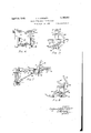
- Fig. 3 is a fractional top view of the cutter bar and its connections to the transmission frame and pitman driving means.
- Fig. 4 is a side elevation of the counter shaft frame.
- Fig. 5 is an end view of the frame as shown in Figure 4 illustrating the counter shaft adjusting means, a fraction of the main frame and a fraction of the cutter bar connections.
- Fig. 6 is a drawing illustrating fractionally the cutter bar lever connections.
- Fig. '7 is an enlarged fractional top view of the front end of the frame and its connection to the draw bar.
- Fig. 8 is a sectional view of the frame taken on line 8-8 of Figure 7.
- Fig. 9 is an enlarged fractional side elevation I of the frame as illustrated in Figure '1.
- Fig. 11 is a rear view of the draft link.
- Fig. 12 is a diagrammatic top view of the attachment illustrating a position of the frame taken after the trip has been released.
- a fraction of a tractor is shown, which is designated by reference character A having a draw bar 8.
- I mount a ball 9 on one endof bar 8 by means of a suitable neck, having a flange and nut as clearly illustrated in Figure 9.
- the frame of my attachment is designated in its entirety by reference character B and the cutter bar in its entirety by reference character C.
- Frame B comprises a square tube i 0, a rear bar I l, a side bar l2, a medial bar l8 and a front bar it the parts being assembled as clearly illustrated in Figure 1.
- the joints between the frame members are secured together by electric welding or otherwise.
- I provide a shaft ill which is slidably mounted in tube i0, the front end protruding as illus trated in Figure 7 and having mounted thereon a two piece socket joint comprising members and 2i which are secured to member ill by means of spaced bolts as clearly illustrated in Figure '1 and being adapted at their front ends to snugly embrace ball 8.
- Member 2i is provided with spaced ears 2222 to which is pivotaliy mounted a release trip 23 by means of bolt 24. I secure a plate 25 to the front upper side of member l0 as illustrated and having a bolt 26 which passes through this plate and frame member It.
- Trip 23 is curved rearwardly and outwardly as at 21 and is also provided with a recess as at 28 and being adapted to engage bolt 28, there'ar or pulling edge being slightly angled whereby it may become disengaged provided the tractor pull is great enough to overcome the tension of spring 29 which is mounted on bolt 30 as illustrated.
- This bolt is provided with a nut 3i whereby the pull necessary to disengage trip 23 may be variously adjusted.
- disengaging means may be provided, the object being solely to hold the cutter bar in its normal position so long as a fixed or serious obstruction is not encountered.
- I provide rear carrying caster wheels "-48 and mount them on the frame preferably'as illustrated. These caster wheels cooperate with the ball and socket joint between members I! and 8. and act to hold the frame A in its normal horizontal position.
- I provide a draft link, which in its entirety is designated by reference character E, comprising a front link 38 and a center bar I! to which rear link 88 is secured. A nut 88 is welded to the front end of member 81 as illustrated.
- Link 38 is adapted to be screw threaded into nut 39 and is locked thereto by means of nut 48.
- Link 38 is hooked into tractor draw bar 8 as illustrated in Figure 1 and link 88 is hooked into a frame plate 4i this plate being secured to frame 3 in a manner to thereby strengthen the Joints between frame members I2, li and I4..
- the frame is stabilized by rear caster wheels and the ball and socket Joint and prevented from swinging on this Joint by draft link E except when trip 28 is released at which time the ball and socket Joint will continue to stabilize the frame but permit it to move rearwardly on shaft i and swing around on the draft link E as illustrated in Figure 12 at which time the draft link is the sole pulling means.
- the draft link will not interfere with the movements of the frame as the caster wheels and tractor pass over uneven ground.
- Member C may be of conventional design com prising a cutter bar 42 having a runner shoe 43 which is hingedly secured to a coupling yoke 44 as at 45-45.
- Yoke 44 is rotatably mounted on the free end of coupling arm 48 (see Figure 3).
- Frame D comprises upper and lower tubes 49 and ill being secured together by means of channel pieces Il-il. Tube lll is rotatably mounted in the lower end of plates 52 and 58,
- plate 52 being secured to frame bar I3 and plate 53 being secured to frame bar II.
- a shaft 54 is rotatably mounted in tube 49 the front end being provided with a universal joint 55 having a shaft 56 which is splined in a sleeve 51.
- I provide a universal joint 58 with which an operating connection is made to the power take-oil shaft 59.
- I rotatably mount a shaft 68, see Figures 3 and 5, in tube 50 having at its front end a crank wheel 88.
- I provide a curved bar 88 which is secured to frame bar 13 by means of bolt 88, the bar being provided with a series of holes and a bolt 1
- the sickle bar of member C is operatively connected to the crank of member 48 by means of pitman 12.
- I provide a collar 13 which is rotatably mounted on the forward end of member 80 to which member 48 is adiustably secured through a projection 14 (see Figure 5).
- a collar II is provided and rotatably mounted on the rear end of tube ill.
- Member 48 is secured to this collar as illustrated in Figures 3 and 5, thus it will be seen that shoe 4! is free to travel over uneven ground and that the cutter bar 42 may be turned or tilted on member 48 in the following manner:
- An arm 80 is provided on member 44 and a lever 8
- Cutter bar 42 is lifted in the conventional manner through an arm 84 and lever 88.
- This lever is provided with a suitable latch and sector and a rearwardly extending portion 88 which is operatively connected to arm 84 by means of link 81.
- my improved mower attachment is simple, strong and compact; that it may easily be attached to the tractor draw bar and easily detached therefrom; that the counter shaft may be conveniently tilted so as to normally be in alignment with the tractor power take-off shaft; that my frame is free to travel over uneven ground and that the caster wheels will permit backing and short turns.
- the cutter bar and frame may swing back without being detached with the draft link as the sole pulling means. Therefore by backing the tractor, the draft link will act as a push bar and the frame will be caused to return to its operating and locked position without inconvenience to the operator. This reset may clearly be accomplished without lifting the cutter bar or the bar may be lifted for the purpose.
- a device of the class described comprising a frame adapted to be drawn and powered by a tractor having two supporting caster wheels mounted on the rear corners thereof.
- a draft link forming a connection from the stubble side of the frame to the hitch bar of the tractor, the other side of the front of the frame extending to near the hitch bar of the tractor and comprising a rectangular tube, a shaft slidably mounted in said tube and having at its forward end a universal joint connection to the hitch bar of the tractor, a cutter bar mounted on said frame and extending laterally from said other side of the frame, an upper and a lower countershaft mounted on the rear of said frame between said caster wheels and being operatively connected together, a crank wheel on the front end of said lower shaft being operatively connected to the sickle of said cutter bar by means of a pitman, a flexible operating connection between the front end of said upper countershaft and the power take-oil of the tractor, an overload releasable connection between the front end of said slidable shaft and said frame
- a mower of the class described comprising a frame adapted to be pulled and powered by a tractor, a laterally extending cutter bar hingedly mounted on said frame, upper and lower countershafts mounted on said frame and having an operating connection between'their rear ends,' a crank wheel mounted on the forward end of said lower shaft and being operatively connected to said cutter bar, the front end of said upper shaft adapted to be operatively connected to the power take-off shaft of the tractor, said upper shaft being rotatably mounted in the upper end of a bracket, the lower end of which is hingedly mounted on the axis of said lower shaft, means whereby said bracket may be held in a predetermined position.
- a device as recited in claim 3 including; said upper shaft being mounted on a bracket having itslower end hingedly mounted concentric with said lower shaft and means whereby said upper shaft may be held in apredetermined transverse position.
- a tractor having a hitch bar of a mower comprising a rigid frame having two supporting castered wheels mounted on the rear corners thereof, a draft link forming a connection from the stubble side of said frame to the adjacent end of said hitch bar and being of a length which will permit free vertical movement of said frame, the other side of said frame extending to near the adjacent end of said hitch bar upper countershaft and said power take-oii anl overload releasable connection between the front and having a tube, a shaft slidably mounted in CHARLES VERN EVERETT.
Description
Ap 1940- c. v. EVERETT I .1 8.910
MOWER ATTACHMENT FOR TRACTORS Filed Sept. 19, 19 58 3 Sheets-Sheet l IN VEN TOR.
A TTORNEY A R-EB 3Q, T940. (3. v. EVERETT 2,1310
MOWER ATTACHMENT FOR TRACTORS' Filed Sept. 19, 1958 3 Sheets-Sheet 2 IN VEN TOR. CHARL 6 Ilse/v [VERE 7 r ATTORNEY T T E R E V E V MOWER ATTACHMENT FOR TRACTORS 3 SheetS-Sheet'S Filed Sept. 19, 1958 INVENTOR. C/MRLZJI/ER/VEVf/PETT TORNEY mama Apr. 30, 1940 PATENT OFFICE 2,198,910 MOWER ATTACHMENT FOB TRACTOR Charles Vern Everett, Racine, Win, aeeignor to The Massey-Harris 00., Racine, Win, a corporation of Maryland Application September 18, 1938, Serial No. 230,688
5 Claims.
The present invention relates to mower attachments for tractorswherein-the entire frame is made stable by two spaced rear :end caster wheels and a forwardly extending inner end which is secured to the draw bar of the tractor by means of a universal joint. The outer forward corner is a distance from the tractor draw bar and has a draft link therebetween thus to cause the attachment to normally follow the tractor in working position.
An object of the present invention is to provide a telescoped joint between the universal joint and the inner side of the frame having a releasable overload device therebetween whereby if the cutter bar meets serious resistance, it and the frame will be permitted to swing rearwardly and prevent breakage.
The telescoped connection is made long enough so contact with the draw bar is not broken whereby the frame will remain stable after itand the cutter bar has swung rearwardly and all that is necessary to return it to its working position is to back the tractor.
Another object of the present invention is to provide means whereby the upper counter shaft may be adjusted to various transverse positions whereby this shaft may be positioned in longitudinal alignment with the power take-ofl shaft of the tractor.
To these and other useful ends my invention consists of parts, combinations of parts or their equivalents, and mode of operation, as hereinafter described and claimed and shown in the accompanying drawings in which:
Fig. l is a fractional top plan view of my improved attachment shown as attached to the draw bar of a tractor.
Fig. 2 is a stubble side elevational view of the attachment as shown in Figure 1.
Fig. 3 is a fractional top view of the cutter bar and its connections to the transmission frame and pitman driving means.
Fig. 4 is a side elevation of the counter shaft frame.
Fig. 5 is an end view of the frame as shown in Figure 4 illustrating the counter shaft adjusting means, a fraction of the main frame and a fraction of the cutter bar connections.
Fig. 6 is a drawing illustrating fractionally the cutter bar lever connections.
' Fig. '7 is an enlarged fractional top view of the front end of the frame and its connection to the draw bar.
Fig. 8 is a sectional view of the frame taken on line 8-8 of Figure 7.
Fig. 9 is an enlarged fractional side elevation I of the frame as illustrated in Figure '1.
side view of the draft- Fig. 10 is an enlarged being sectioned on line link, the medial member Iii-40 of Figure 11.
Fig. 11 is a rear view of the draft link.
Fig. 12 is a diagrammatic top view of the attachment illustrating a position of the frame taken after the trip has been released.
As thus illustrated, a fraction of a tractor is shown, which is designated by reference character A having a draw bar 8. I mount a ball 9 on one endof bar 8 by means of a suitable neck, having a flange and nut as clearly illustrated in Figure 9.
The frame of my attachment is designated in its entirety by reference character B and the cutter bar in its entirety by reference character C.
Frame B comprises a square tube i 0, a rear bar I l, a side bar l2, a medial bar l8 and a front bar it the parts being assembled as clearly illustrated in Figure 1. The joints between the frame members are secured together by electric welding or otherwise.
By scrutinizing Figures 1 and 8it will be seen that member i0 is positioned on the top of members Ii, l3 and It for reasons which will be apparent.
I provide a shaft ill which is slidably mounted in tube i0, the front end protruding as illus trated in Figure 7 and having mounted thereon a two piece socket joint comprising members and 2i which are secured to member ill by means of spaced bolts as clearly illustrated in Figure '1 and being adapted at their front ends to snugly embrace ball 8. v
Member 2i is provided with spaced ears 2222 to which is pivotaliy mounted a release trip 23 by means of bolt 24. I secure a plate 25 to the front upper side of member l0 as illustrated and having a bolt 26 which passes through this plate and frame member It.
I provide rear carrying caster wheels "-48 and mount them on the frame preferably'as illustrated. These caster wheels cooperate with the ball and socket joint between members I! and 8. and act to hold the frame A in its normal horizontal position. I provide a draft link, which in its entirety is designated by reference character E, comprising a front link 38 and a center bar I! to which rear link 88 is secured. A nut 88 is welded to the front end of member 81 as illustrated. Link 38 is adapted to be screw threaded into nut 39 and is locked thereto by means of nut 48. Link 38 is hooked into tractor draw bar 8 as illustrated in Figure 1 and link 88 is hooked into a frame plate 4i this plate being secured to frame 3 in a manner to thereby strengthen the Joints between frame members I2, li and I4..
Thus it will be seen that the frame is stabilized by rear caster wheels and the ball and socket Joint and prevented from swinging on this Joint by draft link E except when trip 28 is released at which time the ball and socket Joint will continue to stabilize the frame but permit it to move rearwardly on shaft i and swing around on the draft link E as illustrated in Figure 12 at which time the draft link is the sole pulling means. Clearly the draft link will not interfere with the movements of the frame as the caster wheels and tractor pass over uneven ground.
I provide a cutter bar which in its entirety is designated by reference character C and mount it to frame B as follows:
Member C may be of conventional design com prising a cutter bar 42 having a runner shoe 43 which is hingedly secured to a coupling yoke 44 as at 45-45. Yoke 44 is rotatably mounted on the free end of coupling arm 48 (see Figure 3).
I mount a collar 41 on member 48 and position it adjacent yoke 44 and screw thread a shaft 48 therein. I provide a counter shaft frame which in its entirety is designated by reference character D. Frame D comprises upper and lower tubes 49 and ill being secured together by means of channel pieces Il-il. Tube lll is rotatably mounted in the lower end of plates 52 and 58,
A shaft 54 is rotatably mounted in tube 49 the front end being provided with a universal joint 55 having a shaft 56 which is splined in a sleeve 51. I provide a universal joint 58 with which an operating connection is made to the power take-oil shaft 59.
I rotatably mount a shaft 68, see Figures 3 and 5, in tube 50 having at its front end a crank wheel 88. I mount sprockets, one being shown in Figure 3, on the rear end of shafts 84 and 85 and operatively connect these sprockets by means of a roller chain (not shown). These sprockets and the chain are adapted to be inclosed within a housing 81.
I provide a curved bar 88 which is secured to frame bar 13 by means of bolt 88, the bar being provided with a series of holes and a bolt 1| acting to hold member D in any desired position in order to cause shaft 84 to be held in vertical alignment with the power take-off shaft 58 thus to accommodate various tractor hitches.
The sickle bar of member C is operatively connected to the crank of member 48 by means of pitman 12. I provide a collar 13 which is rotatably mounted on the forward end of member 80 to which member 48 is adiustably secured through a projection 14 (see Figure 5).
A collar II is provided and rotatably mounted on the rear end of tube ill. Member 48 is secured to this collar as illustrated in Figures 3 and 5, thus it will be seen that shoe 4! is free to travel over uneven ground and that the cutter bar 42 may be turned or tilted on member 48 in the following manner:
An arm 80 is provided on member 44 and a lever 8| is pivotally mounted on frame bar It having a latch and sector and a depending portion 82, which is operatively connected to arm III by means of link 83 thus the operator may conveniently adjust the tilt of the cutter bar.
It will be seen that my improved mower attachment is simple, strong and compact; that it may easily be attached to the tractor draw bar and easily detached therefrom; that the counter shaft may be conveniently tilted so as to normally be in alignment with the tractor power take-off shaft; that my frame is free to travel over uneven ground and that the caster wheels will permit backing and short turns.
Clearly when the release is tripped, the cutter bar and frame may swing back without being detached with the draft link as the sole pulling means. Therefore by backing the tractor, the draft link will act as a push bar and the frame will be caused to return to its operating and locked position without inconvenience to the operator. This reset may clearly be accomplished without lifting the cutter bar or the bar may be lifted for the purpose.
Clearly many minor detail changes may be made without departing from the spirit and scope of the present invention as recited in the a pended claims.
Having thus shown and described my invention, I claim:
1. A device of the class described, comprising a frame adapted to be drawn and powered by a tractor having two supporting caster wheels mounted on the rear corners thereof. a draft link forming a connection from the stubble side of the frame to the hitch bar of the tractor, the other side of the front of the frame extending to near the hitch bar of the tractor and comprising a rectangular tube, a shaft slidably mounted in said tube and having at its forward end a universal joint connection to the hitch bar of the tractor, a cutter bar mounted on said frame and extending laterally from said other side of the frame, an upper and a lower countershaft mounted on the rear of said frame between said caster wheels and being operatively connected together, a crank wheel on the front end of said lower shaft being operatively connected to the sickle of said cutter bar by means of a pitman, a flexible operating connection between the front end of said upper countershaft and the power take-oil of the tractor, an overload releasable connection between the front end of said slidable shaft and said frame whereby when said cutter bar meets serious obstruction, said releasable connection will be disengaged and said cutter bar and frame will be permitted to swing rearwardly with said draft link as a pivot.
2. A mower of the class described, comprising a frame adapted to be pulled and powered by a tractor, a laterally extending cutter bar hingedly mounted on said frame, upper and lower countershafts mounted on said frame and having an operating connection between'their rear ends,' a crank wheel mounted on the forward end of said lower shaft and being operatively connected to said cutter bar, the front end of said upper shaft adapted to be operatively connected to the power take-off shaft of the tractor, said upper shaft being rotatably mounted in the upper end of a bracket, the lower end of which is hingedly mounted on the axis of said lower shaft, means whereby said bracket may be held in a predetermined position.
3. The combination of a tractor having a power take off and a hitch bar,-of a mower com-' prising a frame having two supporting caster wheels mounted on the rear corners thereof, a draft link formingga connection from the front stubble side of the frame to the hitch bar of the tractor, the other side of the front of the frame extending to near the hitch bar of the tractor and comprising a tube, a shaft slidably mounted in said tube and having at its forward end a universal joint connection to said hitch bar, a cutter bar mounted on said frame and extending laterally from the tube side thereof, an upper and a lower countershaft mounted on the rear of said frame between said caster wheels and being operatively connected, a crank wheel on the front end of said lower shaft having a pitman forming an operating connection to said cutter bar, a shaft having means to form a flexible operating connection between the front end of said with said draft link as a pivot.
4. A device as recited in claim 3 including; said upper shaft being mounted on a bracket having itslower end hingedly mounted concentric with said lower shaft and means whereby said upper shaft may be held in apredetermined transverse position.
5. The combination of a tractor having a hitch bar, of a mower comprising a rigid frame having two supporting castered wheels mounted on the rear corners thereof, a draft link forming a connection from the stubble side of said frame to the adjacent end of said hitch bar and being of a length which will permit free vertical movement of said frame, the other side of said frame extending to near the adjacent end of said hitch bar upper countershaft and said power take-oii anl overload releasable connection between the front and having a tube, a shaft slidably mounted in CHARLES VERN EVERETT.
Priority Applications (1)
| Application Number | Priority Date | Filing Date | Title |
|---|---|---|---|
| US230638A US2198910A (en) | 1938-09-19 | 1938-09-19 | Mower attachment for tractors |
Applications Claiming Priority (1)
| Application Number | Priority Date | Filing Date | Title |
|---|---|---|---|
| US230638A US2198910A (en) | 1938-09-19 | 1938-09-19 | Mower attachment for tractors |
Publications (1)
| Publication Number | Publication Date |
|---|---|
| US2198910A true US2198910A (en) | 1940-04-30 |
Family
ID=22865995
Family Applications (1)
| Application Number | Title | Priority Date | Filing Date |
|---|---|---|---|
| US230638A Expired - Lifetime US2198910A (en) | 1938-09-19 | 1938-09-19 | Mower attachment for tractors |
Country Status (1)
| Country | Link |
|---|---|
| US (1) | US2198910A (en) |
Cited By (9)
| Publication number | Priority date | Publication date | Assignee | Title |
|---|---|---|---|---|
| US2471311A (en) * | 1944-09-28 | 1949-05-24 | Deere & Co | Mower |
| US2520107A (en) * | 1943-05-26 | 1950-08-22 | Avco Mfg Corp | Release mechanism for mowers |
| US2520743A (en) * | 1946-10-24 | 1950-08-29 | Allis Chalmers Mfg Co | Break-back implement attachment for tractors |
| US2520744A (en) * | 1946-10-31 | 1950-08-29 | Allis Chaimers Mfg Company | Break-back implement attachment for tractors |
| US2520745A (en) * | 1946-11-25 | 1950-08-29 | Allis Chalmers Mfg Co | Break-back mower |
| US2555541A (en) * | 1947-08-16 | 1951-06-05 | Int Harvester Co | Control means for mower cutter bars |
| US2592866A (en) * | 1946-11-09 | 1952-04-15 | Deere & Co | Implement draft connection |
| US2686658A (en) * | 1951-05-11 | 1954-08-17 | New Holland Machine Division O | Trail mower jack |
| US9032573B2 (en) | 2011-06-01 | 2015-05-19 | David Mijan | Bed vibration system and method |
-
1938
- 1938-09-19 US US230638A patent/US2198910A/en not_active Expired - Lifetime
Cited By (9)
| Publication number | Priority date | Publication date | Assignee | Title |
|---|---|---|---|---|
| US2520107A (en) * | 1943-05-26 | 1950-08-22 | Avco Mfg Corp | Release mechanism for mowers |
| US2471311A (en) * | 1944-09-28 | 1949-05-24 | Deere & Co | Mower |
| US2520743A (en) * | 1946-10-24 | 1950-08-29 | Allis Chalmers Mfg Co | Break-back implement attachment for tractors |
| US2520744A (en) * | 1946-10-31 | 1950-08-29 | Allis Chaimers Mfg Company | Break-back implement attachment for tractors |
| US2592866A (en) * | 1946-11-09 | 1952-04-15 | Deere & Co | Implement draft connection |
| US2520745A (en) * | 1946-11-25 | 1950-08-29 | Allis Chalmers Mfg Co | Break-back mower |
| US2555541A (en) * | 1947-08-16 | 1951-06-05 | Int Harvester Co | Control means for mower cutter bars |
| US2686658A (en) * | 1951-05-11 | 1954-08-17 | New Holland Machine Division O | Trail mower jack |
| US9032573B2 (en) | 2011-06-01 | 2015-05-19 | David Mijan | Bed vibration system and method |
Similar Documents
| Publication | Publication Date | Title |
|---|---|---|
| US4573309A (en) | Pull-type windrower | |
| US2198910A (en) | Mower attachment for tractors | |
| US3731469A (en) | Convertible gang lawn mower | |
| US2248332A (en) | Power transmitting device | |
| US1947552A (en) | Mower | |
| US2171761A (en) | Mower | |
| US2340488A (en) | Mower | |
| US2454697A (en) | Tractor mower | |
| US2314215A (en) | Mower | |
| US2630185A (en) | Power unit for lawn mowers | |
| US2707643A (en) | Tractor-implement hitch mechanism | |
| US2217332A (en) | Power transmitting device | |
| US2331863A (en) | Tractor mower | |
| US2496469A (en) | Front-mounted tractor mower | |
| US1974410A (en) | Mower | |
| US2318202A (en) | Tractor mower | |
| US2520107A (en) | Release mechanism for mowers | |
| US2686658A (en) | Trail mower jack | |
| US2494757A (en) | Tractor hitch | |
| US2520743A (en) | Break-back implement attachment for tractors | |
| US3320730A (en) | Corn picker | |
| US2463726A (en) | Mowing machine | |
| US2476439A (en) | Releasable power lift connection | |
| US2155716A (en) | Power mower | |
| US2148311A (en) | Mowing machine |