US2184997A - Radio antenna - Google Patents
Radio antenna Download PDFInfo
- Publication number
- US2184997A US2184997A US126391A US12639137A US2184997A US 2184997 A US2184997 A US 2184997A US 126391 A US126391 A US 126391A US 12639137 A US12639137 A US 12639137A US 2184997 A US2184997 A US 2184997A
- Authority
- US
- United States
- Prior art keywords
- wire
- antenna
- radio
- collector
- radio antenna
- Prior art date
- Legal status (The legal status is an assumption and is not a legal conclusion. Google has not performed a legal analysis and makes no representation as to the accuracy of the status listed.)
- Expired - Lifetime
Links
Images
Classifications
-
- H—ELECTRICITY
- H01—ELECTRIC ELEMENTS
- H01Q—ANTENNAS, i.e. RADIO AERIALS
- H01Q1/00—Details of, or arrangements associated with, antennas
- H01Q1/36—Structural form of radiating elements, e.g. cone, spiral, umbrella; Particular materials used therewith
-
- Y—GENERAL TAGGING OF NEW TECHNOLOGICAL DEVELOPMENTS; GENERAL TAGGING OF CROSS-SECTIONAL TECHNOLOGIES SPANNING OVER SEVERAL SECTIONS OF THE IPC; TECHNICAL SUBJECTS COVERED BY FORMER USPC CROSS-REFERENCE ART COLLECTIONS [XRACs] AND DIGESTS
- Y10—TECHNICAL SUBJECTS COVERED BY FORMER USPC
- Y10T—TECHNICAL SUBJECTS COVERED BY FORMER US CLASSIFICATION
- Y10T428/00—Stock material or miscellaneous articles
- Y10T428/12—All metal or with adjacent metals
- Y10T428/12333—Helical or with helical component
-
- Y—GENERAL TAGGING OF NEW TECHNOLOGICAL DEVELOPMENTS; GENERAL TAGGING OF CROSS-SECTIONAL TECHNOLOGIES SPANNING OVER SEVERAL SECTIONS OF THE IPC; TECHNICAL SUBJECTS COVERED BY FORMER USPC CROSS-REFERENCE ART COLLECTIONS [XRACs] AND DIGESTS
- Y10—TECHNICAL SUBJECTS COVERED BY FORMER USPC
- Y10T—TECHNICAL SUBJECTS COVERED BY FORMER US CLASSIFICATION
- Y10T428/00—Stock material or miscellaneous articles
- Y10T428/12—All metal or with adjacent metals
- Y10T428/12493—Composite; i.e., plural, adjacent, spatially distinct metal components [e.g., layers, joint, etc.]
- Y10T428/12736—Al-base component
- Y10T428/12743—Next to refractory [Group IVB, VB, or VIB] metal-base component
-
- Y—GENERAL TAGGING OF NEW TECHNOLOGICAL DEVELOPMENTS; GENERAL TAGGING OF CROSS-SECTIONAL TECHNOLOGIES SPANNING OVER SEVERAL SECTIONS OF THE IPC; TECHNICAL SUBJECTS COVERED BY FORMER USPC CROSS-REFERENCE ART COLLECTIONS [XRACs] AND DIGESTS
- Y10—TECHNICAL SUBJECTS COVERED BY FORMER USPC
- Y10T—TECHNICAL SUBJECTS COVERED BY FORMER US CLASSIFICATION
- Y10T428/00—Stock material or miscellaneous articles
- Y10T428/12—All metal or with adjacent metals
- Y10T428/12493—Composite; i.e., plural, adjacent, spatially distinct metal components [e.g., layers, joint, etc.]
- Y10T428/12771—Transition metal-base component
- Y10T428/12861—Group VIII or IB metal-base component
- Y10T428/12903—Cu-base component
Definitions
- This invention relates to radio antenna for use with all radios.
- the object of the invention is to provide a highly effective antenna that is convenient in 5 size and weight for permanent trouble-free installation for ordinary home use.
- a further object is to provide an antenna of higher efficiency than the conventional aerial wires now in use.
- a still further object is to provide a multiple wire antenna, variable by selective circuits for variable antenna usage.
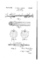
- Fig. l is a broken isometric view of my antenna
- Fig. 2 is an enlarged broken sectional view of the antenna wire proper showing the smaller wire embedded in the larger and the knurled surface;
- Fig. 3 is an enlarged right angle cross section of the two antenna wires as they are fit together in the spirally formed groove in the .larger wire;
- Fig. 4 is a view similar to Fig. 3 after the two wires have been locked together in the spiral groove by a knurling or roughening operation;
- Fig. 5 is a diagrammatic view showing a variation of the antenna circuits to be described later.
- the numeral H3 designates the large wire which is of light metal into which a spiral groove has been milled.
- I use a one-quarter inch diameter aluminum wire.
- the numeral H is a smaller wire of different radio frequency conductor characteristics. I prefer to use copper for this smaller 4 wire and to obtain variations in results I make this wire either shorter or longer than the larger aluminum wire, insulate it from the larger wire and/or cover the smaller wire with nickel, tin, silver, lead or other metals of different electrical 4:5 conductivity.
- As a trial and error experimentor with radio antennas I have discovered that such variations as alcove give variable-results and altho I do not know the absolute scientific reasons, the results have been quite successful.
- the numeral i2 designates a conventional form of end clip attached to the antenna by bolts 13.
- a suitable ring it connects the clips IE to conventional insulators lii'and the feeder wire it leads to the antenna post on the radio re- 55 DCver.
- the spiral groove I1 is shown with the small wire I I inserted therein.
- Fig. 4 I show how the lips of the groove I! have been inverted over the wire H by the knurls l9 securely sealing the wire I l in the spiral groove. 5
- the knurling I9 is of a form to greatly increase the surface area of the antenna wire by covering the surface with innumerable projections and pits.
- Fig. 5 I have indicated by diagram means by which I make a non-tuneable double antenna wherein the two circuits, using wires Ii and H, are insulated apart but built into a single wire giving a general purpose all-wave antenna, wherein, by special coupling, eight different an- 15 tenna combinations are available.
- I produce a dual metal, dual surface aerial combining electrical and structural advantage of both wires in a single antenna; by insulating the wires from each other I obtain a multiple aerial in a single wire.
- a radio frequency collector wire of aluminum alloy a radio frequency collector wire of aluminum alloy, a spiral groove in said collector wire, and an insulated copper conductor wire extending from one end of said groove to a point short of the full length thereof,
- said collector and conductor having approximately 1.6 micro-micro farad capacity per inch.
- a radio frequency collector wire of aluminum alloy approximately 20' in length, a knurled surface on said wire to increase wire surface area projecting in all directions, a spiral groove in said collector and an insulated copper conductor wire extending from one end of said groove three or more feet in said collector Wire, whereby said conductor wire is shorter than the collector wire to provide variable transmission capacity in the antenna.
- a radio antenna generally as described in claim 4, having the same proportionate wire capacities whereby radio frequency impulses from 600 to 60,000 kilocycles are received and transmitted.
Landscapes
- Details Of Aerials (AREA)
Description
Dec. 26, 1939.- H. (HEINIE) JOHNSON ,997
mmo ANTENNA Filed Feb. 18, 1937 T M (Maw j I INVENTOR.
sY f-ffl s ATTORNEY.
Patented Dec. 26, 1939 ill ii'lfiil STATES RADIG ANTENNA Henry (Heinie) L. Johnson, Bloomington, Ill.
Application February 18, 1937, Serial No. 126,391
Claims.
This invention relates to radio antenna for use with all radios. I
The object of the invention is to provide a highly effective antenna that is convenient in 5 size and weight for permanent trouble-free installation for ordinary home use.
A further object is to provide an antenna of higher efficiency than the conventional aerial wires now in use.
And a still further object is to provide a multiple wire antenna, variable by selective circuits for variable antenna usage.
Other objects and benefits will be disclosed by the following drawing and specification in which:
Fig. l is a broken isometric view of my antenna;
Fig. 2 is an enlarged broken sectional view of the antenna wire proper showing the smaller wire embedded in the larger and the knurled surface;
Fig. 3 is an enlarged right angle cross section of the two antenna wires as they are fit together in the spirally formed groove in the .larger wire;
Fig. 4 is a view similar to Fig. 3 after the two wires have been locked together in the spiral groove by a knurling or roughening operation;
and
Fig. 5 is a diagrammatic view showing a variation of the antenna circuits to be described later. Now referring to the illustrations, the same part is designated by the same reference numeral wherever it occurs throughout the several views. The numeral H3 designates the large wire which is of light metal into which a spiral groove has been milled. In the preferred embodiment of my invention, I use a one-quarter inch diameter aluminum wire. The numeral H is a smaller wire of different radio frequency conductor characteristics. I prefer to use copper for this smaller 4 wire and to obtain variations in results I make this wire either shorter or longer than the larger aluminum wire, insulate it from the larger wire and/or cover the smaller wire with nickel, tin, silver, lead or other metals of different electrical 4:5 conductivity. As a trial and error experimentor with radio antennas, I have discovered that such variations as alcove give variable-results and altho I do not know the absolute scientific reasons, the results have been quite successful.
59 The numeral i2 designates a conventional form of end clip attached to the antenna by bolts 13. A suitable ring it connects the clips IE to conventional insulators lii'and the feeder wire it leads to the antenna post on the radio re- 55 ceiver.
Referring to Fig. 3, the spiral groove I1 is shown with the small wire I I inserted therein. In Fig. 4 I show how the lips of the groove I! have been inverted over the wire H by the knurls l9 securely sealing the wire I l in the spiral groove. 5
The knurling I9 is of a form to greatly increase the surface area of the antenna wire by covering the surface with innumerable projections and pits.
In Fig. 5 I have indicated by diagram means by which I make a non-tuneable double antenna wherein the two circuits, using wires Ii and H, are insulated apart but built into a single wire giving a general purpose all-wave antenna, wherein, by special coupling, eight different an- 15 tenna combinations are available.
Many variations of this same idea are, of course, possible and I illustrate this example only to disclose the scheme.
To explain the advantages of my antenna and 20 its structure, I desire to explain that because of the large diameter of the wire and its greatly increased surface area. I can get effective results with a relatively short length of wire. This short length of large diameter wire is both light and 25 stiff, and, as a result, it may be mounted in a small space and held rigidly and permanently in position. It will be appreciated that my mounting of the small wire in the larger is a rigid construction that will inhibit extraneous noises. 39 Further, that the knurled or expanded surface of the larger wire and spiral winding of the smaller wire provides a multi-directional structure distinctively different from the conventional aerial Wire. 35
By using bare wires, I produce a dual metal, dual surface aerial combining electrical and structural advantage of both wires in a single antenna; by insulating the wires from each other I obtain a multiple aerial in a single wire. 40
In the foregoing I have disclosed what I now consider to be the preferred embodiment of my invention, However, as I have indicated, numerous optional structures are possible and I do not desire to be limited to the structure shown except as by the appended claims.
I now claim as new:
1. In a radio antenna, a radio frequency collector wire of aluminum alloy, a spiral groove in said collector wire, and an insulated copper conductor wire extending from one end of said groove to a point short of the full length thereof,
' said collector and conductor having approximately 1.6 micro-micro farad capacity per inch.
2. In a radio antenna, a radio frequency col- 'farad capacity per inch.
3. In a radio antenna, a radio frequency collector wire of aluminum alloy approximately 20' in length, a knurled surface on said wire to increase wire surface area projecting in all directions, a spiral groove in said collector and an insulated copper conductor wire extending from one end of said groove three or more feet in said collector Wire, whereby said conductor wire is shorter than the collector wire to provide variable transmission capacity in the antenna.
4. In a radio antenna, a radio frequency collector Wire of aluminum alloy approximately A" in diameter and 20' in length, a knurled surface on said wire to increase wire surface area projecting in all directions, a spiral groove in said collector, and an insulated copper conductor wire of approximately 20 gauge, extending about 13 7" in said groove of the collector wire whereby radio frequency impulses from 600 to 60,000 kilocycles are received and transmitted.
5. A radio antenna generally as described in claim 4, having the same proportionate wire capacities whereby radio frequency impulses from 600 to 60,000 kilocycles are received and transmitted.
HENRY (HEINIE) L. JOHNSON.
Priority Applications (1)
| Application Number | Priority Date | Filing Date | Title |
|---|---|---|---|
| US126391A US2184997A (en) | 1937-02-18 | 1937-02-18 | Radio antenna |
Applications Claiming Priority (1)
| Application Number | Priority Date | Filing Date | Title |
|---|---|---|---|
| US126391A US2184997A (en) | 1937-02-18 | 1937-02-18 | Radio antenna |
Publications (1)
| Publication Number | Publication Date |
|---|---|
| US2184997A true US2184997A (en) | 1939-12-26 |
Family
ID=22424567
Family Applications (1)
| Application Number | Title | Priority Date | Filing Date |
|---|---|---|---|
| US126391A Expired - Lifetime US2184997A (en) | 1937-02-18 | 1937-02-18 | Radio antenna |
Country Status (1)
| Country | Link |
|---|---|
| US (1) | US2184997A (en) |
Cited By (3)
| Publication number | Priority date | Publication date | Assignee | Title |
|---|---|---|---|---|
| US3262302A (en) * | 1965-02-03 | 1966-07-26 | Auto Soler Co | Method of forming threaded wire |
| US3896261A (en) * | 1974-04-15 | 1975-07-22 | Belden Corp | Coaxial cable with an undulated drain wire |
| US11053793B2 (en) * | 2016-12-22 | 2021-07-06 | Halliburton Energy Services, Inc. | Single layer antenna path profile |
-
1937
- 1937-02-18 US US126391A patent/US2184997A/en not_active Expired - Lifetime
Cited By (3)
| Publication number | Priority date | Publication date | Assignee | Title |
|---|---|---|---|---|
| US3262302A (en) * | 1965-02-03 | 1966-07-26 | Auto Soler Co | Method of forming threaded wire |
| US3896261A (en) * | 1974-04-15 | 1975-07-22 | Belden Corp | Coaxial cable with an undulated drain wire |
| US11053793B2 (en) * | 2016-12-22 | 2021-07-06 | Halliburton Energy Services, Inc. | Single layer antenna path profile |
Similar Documents
| Publication | Publication Date | Title |
|---|---|---|
| US3123826A (en) | durham | |
| EP0734092A1 (en) | Inductive coupled extendable antenna | |
| US3184747A (en) | Coaxial fed helical antenna with director disk between feed and helix producing endfire radiation towards the disk | |
| US2471256A (en) | Radio antenna | |
| US2273955A (en) | Loop antenna | |
| US2636986A (en) | Television antenna | |
| US2184997A (en) | Radio antenna | |
| US2144310A (en) | Radio apparatus and method of manufacture | |
| US2313513A (en) | Antenna | |
| US3961332A (en) | Elongated television receiving antenna for indoor use | |
| US3491361A (en) | Endfire antenna array having loop directors | |
| US3550145A (en) | Manipole broadband antenna | |
| US3541567A (en) | Multielement radio-frequency antenna structure having linearly arranged elements | |
| US3241149A (en) | Single rod antenna | |
| US2498350A (en) | Shock mount for collapsible antennas | |
| US2213276A (en) | Directional antenna system | |
| US3390394A (en) | Dual loop antenna | |
| US2048726A (en) | Transmitting antenna for obtaining reduced high angle radiation | |
| US2153298A (en) | Aerial | |
| US2008286A (en) | Circuit connection for ultra short waves | |
| US2632107A (en) | Television antenna | |
| US3268899A (en) | Cylindrical tube antenna with matching transmission line | |
| US1610704A (en) | Means for increasing the capacity of radioaerials | |
| US2748387A (en) | Antenna structure | |
| US2724053A (en) | Whip-type antennae |