US2179556A - Method of making turbines - Google Patents
Method of making turbines Download PDFInfo
- Publication number
- US2179556A US2179556A US125647A US12564737A US2179556A US 2179556 A US2179556 A US 2179556A US 125647 A US125647 A US 125647A US 12564737 A US12564737 A US 12564737A US 2179556 A US2179556 A US 2179556A
- Authority
- US
- United States
- Prior art keywords
- creep
- turbine
- parts
- metal
- rotor
- Prior art date
- Legal status (The legal status is an assumption and is not a legal conclusion. Google has not performed a legal analysis and makes no representation as to the accuracy of the status listed.)
- Expired - Lifetime
Links
Images

Classifications
-
- B—PERFORMING OPERATIONS; TRANSPORTING
- B23—MACHINE TOOLS; METAL-WORKING NOT OTHERWISE PROVIDED FOR
- B23P—METAL-WORKING NOT OTHERWISE PROVIDED FOR; COMBINED OPERATIONS; UNIVERSAL MACHINE TOOLS
- B23P15/00—Making specific metal objects by operations not covered by a single other subclass or a group in this subclass
- B23P15/006—Making specific metal objects by operations not covered by a single other subclass or a group in this subclass turbine wheels
-
- F—MECHANICAL ENGINEERING; LIGHTING; HEATING; WEAPONS; BLASTING
- F01—MACHINES OR ENGINES IN GENERAL; ENGINE PLANTS IN GENERAL; STEAM ENGINES
- F01D—NON-POSITIVE DISPLACEMENT MACHINES OR ENGINES, e.g. STEAM TURBINES
- F01D11/00—Preventing or minimising internal leakage of working-fluid, e.g. between stages
- F01D11/08—Preventing or minimising internal leakage of working-fluid, e.g. between stages for sealing space between rotor blade tips and stator
-
- F—MECHANICAL ENGINEERING; LIGHTING; HEATING; WEAPONS; BLASTING
- F01—MACHINES OR ENGINES IN GENERAL; ENGINE PLANTS IN GENERAL; STEAM ENGINES
- F01D—NON-POSITIVE DISPLACEMENT MACHINES OR ENGINES, e.g. STEAM TURBINES
- F01D5/00—Blades; Blade-carrying members; Heating, heat-insulating, cooling or antivibration means on the blades or the members
-
- Y—GENERAL TAGGING OF NEW TECHNOLOGICAL DEVELOPMENTS; GENERAL TAGGING OF CROSS-SECTIONAL TECHNOLOGIES SPANNING OVER SEVERAL SECTIONS OF THE IPC; TECHNICAL SUBJECTS COVERED BY FORMER USPC CROSS-REFERENCE ART COLLECTIONS [XRACs] AND DIGESTS
- Y10—TECHNICAL SUBJECTS COVERED BY FORMER USPC
- Y10T—TECHNICAL SUBJECTS COVERED BY FORMER US CLASSIFICATION
- Y10T29/00—Metal working
- Y10T29/49—Method of mechanical manufacture
- Y10T29/49316—Impeller making
- Y10T29/4932—Turbomachine making
Definitions
- the present invention relates to turbines adapted -to operate with motive fluid at high temperature and has particular reference to the manufacture of and material for turbine parts subjected to severe temperature and/or mechanical stress conditions during normal operation of the turbine. Still more particularly the inven-v tion relates to manufacture of and material for turbine rotor parts, particularly the rotor blading and the rotor parts for carrying the same.
- a fundamental characteristic of this phenomenon of creep is that it is not uniform with respect to time. Assuming the metal to be subjected to creep producing conditions, the creep is initially at a comparatively rapid rate, and asthe length of time of service of the metal under the creep producing conditions continues, the rate of creep diminishes because of the so-called hardening strains set up in the metal after it has been in service for a considerable period of time under 4 creep adversely affects the performance of the turbine. Thus, if in a particular instance creep operates to cause an enlargement of a clearance, the rate of creep causes such enlargement tovoccur (o1.
- the parts may be finished to provide desirably close initial clearances and the remaining creep which will occur during the normal life of the turbine, being secondary creep of relatively very low rate and relatively small magnitude, will not seriously interfere with the operation or emciency of the turbine when these factors are considered in the light of the total life of the turbine.
- Fig. 1 is a diagram showing the general nature of the primary and secondary creep which occurs in-metals.
- Fig. 2 is a diagrammatic view partly in section illustrating an apparatus for eiecting the proposed creep producing treatment.
- Fig. 3 is a fragmentary section showing a portion of an axial flow turbine rotor and casing structure made in accordance with the invention.
- Figui is a similar view of another form of axial flow turbine rotor construction.
- Fig. 5 isa view showing a rotor blade ring for a radial ow turbine.
- the parts in which creep is to be produced may be subjected to heat and mechanical stress by various different kinds of apparatus, but the nature of the parts to be treated is usually such that the mechanical stress is advantageously applied by subjecting the parts to the centrifugal force developed by high rotative speeds.
- the apparatus comprises a suitably mounted stationary casing II] providing a heating chamber I2, access to which is afforded by the removable cover plate I4.
- any suitable means may be employed for heating the interior of chamber I2 to high temperature. Hot steam, gas or air may be passed through the chamber, but for reasons which will be explained, electric heating units, such as in-l dicated at 22, may advantageously be employed. In order to increase the heatingefliciency the walls of the chamber may advantageously be heat insulated as at 24.
- the end of shaft I6 which extends into chamber I2 may be equipped with any suitable means for attachment thereto of the part or parts to be treated.
- any suitable means for attachment thereto of the part or parts to be treated By way of example I have shown mounted for treatment a turbine blade carrier having welded thereto at its circumference, by means vof welds 34, a ring of turbine blades 32. The blades 32 are surrounded by the outer shroud ring 36.
- Carrier is conveniently mounted by means of a number of radial pins 38 'extending into suitable recesses in the carrier and removable through the socket 4I) to release the carrier..
- the blade carrier 30, which may be one of the elements for forming a built-up turbine rotor'of the kind shown in Fig. 4, is advantageously magnufactured to semi-ilnished dimensions, the blades 32 welded thereto and the assembly heat treated 4 to remove welding strains before being placed in the treating chamber.
- the carrier In the treating chamber the carrier is then rotated under excess temperature conditions of the order given in the table previously set forth and at a speed which will over-stress the parts, due to centrifugal force, to the desired degree.
- the chamber I2 is preferably evacuated4 by the vacuum pump so as to minimize windage losses and consequently reduce the amount of power required for the operation.
- the treatment is ycontinued for the length of time required to produce the percentage of increase in dimension of the parts desired for the particular parts being treated.
- Such increase in dimension may very readily be measured, either optically or electrically and by way of illustration I have shown an electrical device consisting of a contact electrode42 adjustably moimted in the casing III in any convenient manner and insulated therefrom, .which electrode forms one terminal .of an open electric circuit 44 energized by a current source such as a battery 46 and including afsignal such as a buzzer or lamp 48 which is energized when the circuit is closed.
- Casing IIJ forms a part of the circuit and the civ:- cuit is closed when-contact is made between the electrode 42 and the periphery of the part being It will be evident with an arrangement such as this ythe electrode 42 can initially be set so that closing of the circuit will be effected only after the diameter of the part being treated has increased, due to creep, by the predetermined amount.
- the treatedl part is allowed to cool and is then nished to nal dimensions.
- finishing to flnal dimensions is employed in the sense of dening that step or those steps of machining by cutting, broaching, grinding, or the like required to bring the parts so finished to desired flnal dimensional size as, for example, that speciiied on shop drawings, independent of additional operations such as straightening or the removal or addition of localized bodies of metal possibly required to balance a rotating part which has been nished to nal dimensions.v It will be evident that prior to treatment it will be necessary to leave unfinished only those dimensions which involve the iitting of the part to other parts and/or which involve the determination of the clearance spaces within the turbine.
- FIG. 3 the construction illustrated shows carrier discs of the kind shown in Fig. 2, the rotor assembly'being formed by carriers 30, the hub portions of which are recessed as at 50 to receive spacer rings 52.
- the spacer rings and the carriers are advantageously bolted together as by means of bolts 54 which serve to hold the assembly together while it is welded as at 56.
- end pieces providing journals for the rotor are secured in known manner, the general form of built-up rotor structure being of known character.
- ture and mechanical stress'conditions and such groups of parts may conveniently be treated simultaneously to produce the initial creep in the parts.
- two carriers with their intermediate spacing 4ring 52 may be treated as a unit, but in this connection it'is to be noted that-in such treatment the parts should be of balanced construction so that the mechanical stresses will be evenly distributed.
- an assembly consisting of one carrier 30 and one ring 52 should not be treated together since if this were done the ring 452 would not be evenly stressed, the extending or free end of the ring end attached to the disc, since the larger ⁇ diameter of the disc will cause greater stresses to be induced therein than in the ring, with a consequent tendency of the disc to stretch more than the ring and stretch the attached end of the ring more than the free end.
- the construction of the turbine casing is advantageously of the form indicated in Fig.- 3 in which it is made up of a'number of sections 5B being subjected to less stretching force than the welded together at 60 and having welded thereto the stationary diaphragms 62 comprising outer and inner rings 64 and 66 respectively, between which are secured the stationary turbine blades Leakage past the various blade rings is reduced by the usual packing strips 10 illustrated more or less diagrammatically in Fig. 3, some of these strips being carried by the rotor structure and some by the stationary structure.
- the ribs 12 at the outer circumference of the shroud rings 36 may also function as radially disposed packing means.
- the casing rings 58 may be advantageously parted along a central plane, the turbine casing being formed in two-halves held together by means of suitable bolts 14.
- Fig. 4 illustrates another form of axial flow rotor'construction in which the blade carriers 30a are provided with laterally extending hub portions 30b,-which hub portions take the place of the spacer rings 52 in the form of construction shown in Fig. 3. These hub portions are directly welded together as at 16 and are advantageously provided with centering fianges 18. The nature of the treatment to be given these carriers will be obvious from the previously described form.
- That improvement in the manufacture of a metal member intended for use under creep producing conditions in a turbine which consists in subjecting the member to creep'producing conditions of greater severity than those to which it would be subjected in its'intended service, continuing such treatment until the rate at which creep occurs appreciably diminishes due to hardducing conditions in a turbine which consists in concomitantly subjecting the member to mechanical stress substantially greater than the normal operating stress in the turbine and to a temperature above the normal operating tem-' perature in the turbine, continuing such treatm'ent until at least a substantial portion of the initial creep of the metal has been produced and thereafter finishing the member to required final dimensions.
- That improvement in the manufacture of built-up turbine rotors for use under normal operating conditions of temperature and mechanical stress productive of creep in the metal of the rotor which includes the steps of rotating omponent parts of the rotor at speeds sufficiently higher than their normal operating speed to produce therein stresses substantially higher than those encountered in normal operation, maintaining such parts'at temperatures in excess of those encountered in normal operation while they are subjected to the excess stresses produced by such rotation, continuing such rotation until a consists'in 8.
- That improvement in the manufacture of a metal member intended for use under creep producing conditions in a turbine which consists in subjecting the member for a minimum period of the order of thirty hours to mechanical stress of at least the order of twice the mechanical stress to which it would be subjected in its intended service while maintainingthe member at a temperature above that at which it would operate in its intended service, and thereafter iinishing the member to its required nal dimensions.
Landscapes
- Engineering & Computer Science (AREA)
- Mechanical Engineering (AREA)
- General Engineering & Computer Science (AREA)
- Turbine Rotor Nozzle Sealing (AREA)
Description
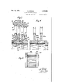
Nov. 14, 1939. A ,YSHQLM .2.179.556
METHOD OF MAKING TURBINES Filed Feb. 13, 1937 2 Sheets-Sheet 1 Falcn/a7 Creep MORNEY.
NOV. 14, 1939. A LYSHOLM 2.179.556
METHOD OF MAKING TURBINES Filed Feb: 13, 1957 2 Sheets-Shea. 2
by. 5 l
INV NToR. BY v ATTORNEY.
Patented Nov. 14, 1939 UNITED STATES METHOD 0F MAKING TURBINES Alf Lysholm, Stockholm, Sweden, assignor to Aktiebolaget Milo, Stockholm, Sweden, a corporation of Sweden Application February 13, 1937, Serial No. 125,647
In Great Britain March 8, 1933 L 10 Claims.
Thisv application is a continuation in part with respect to my copending application Serial No. 713,904, filed March 3, 1934, and as to common subject matter, relates back to said application Serial No. 713,904.
The present invention relates to turbines adapted -to operate with motive fluid at high temperature and has particular reference to the manufacture of and material for turbine parts subjected to severe temperature and/or mechanical stress conditions during normal operation of the turbine. Still more particularly the inven-v tion relates to manufacture of and material for turbine rotor parts, particularly the rotor blading and the rotor parts for carrying the same.
When steels of the kind usually used for turbine blading and rotor structure are continuously and concomitantly subjected to high temperature and high mechanical stresses, they are subject to a physical change in the form of a permanent growth which is different from the enlargement resulting merely from the temporary expansion of the metal under the influence of heat alone. This permanent growth is known as creep, and while the amount of increase in volume of the metal due to the creep is relatively small compared to the total volume of the metal, it is sufficient to alter the dimensions of the parts within a turbine, and particularly the clearances, when it occurs in the metal of the turbine structure.
A fundamental characteristic of this phenomenon of creep is that it is not uniform with respect to time. Assuming the metal to be subjected to creep producing conditions, the creep is initially at a comparatively rapid rate, and asthe length of time of service of the metal under the creep producing conditions continues, the rate of creep diminishes because of the so-called hardening strains set up in the metal after it has been in service for a considerable period of time under 4 creep adversely affects the performance of the turbine. Thus, if in a particular instance creep operates to cause an enlargement of a clearance, the rate of creep causes such enlargement tovoccur (o1. zii-156s) after the turbine has been -in service for a comparatively short proportion of its useful life and thereafter the turbine must operate with aconsiderably larger than desirable clearance at such place. This cannot be avoided by making the parts oversize to'begin with since the desirable maximum clearances are so small that the parts would be in contact and would bind if initially made so as to compensate for the increase in clearance which would be produced by the subsequent creep. In the case of a reduction in clearance due to creep, the necessary initial allowance for the clearance spaces to avoid subsequent contact of the parts after the creep had taken place and reduced the clearance spaces would require initial clearances too great to be eilicient, which clearances would remain too great for a substantial time of operation. As noted above, creep is gradual and it is also relatively slow. In some instances, many hundreds or even thousands of hours of operation may be required to effect the total or substantially total amount of creep that will be produced in the metal owing to the stresses of operation in the turbine. l
In built-up turbine rotor structures, creep is productive of other undesirable conditions as well as change in clearances. One such condition is the loosening of parts due to the change in dimen- -sions thereof. It has previously been 'suggested to avoid this latter diflculty by welding together of the assembled parts, and so-called seasoning of rotors has been resorted to in some instances in the belief that local over stressing of material, which is relieved by such seasoning, and whichmay be occasioned by welding or other strains occasioned by the assembling, are responsible for the difiiculties encountered with turbine structures exposed to creep producing conditions. Loosening of parts of assembled rotors,vwhich may be attributed to creep, may be avoided by making assemblies, such as blades and blade carriers, integral, but such construction is extremely expensive as compared with built up structures. Moreover, integral construction does' not avoid the diniculties occasioned by the adverse effect of creep upon the clearance spaces in the turbine.
In accordance with the present invention, I Ypropose to substantially reduce-.and for all practical purposes eliminate the diiculties heretofore encountered because of creep in turbine parts by producing creep in the parts subjected to creep producing conditions, prior to the nal finishing and assembly of such partsA in the turbine.
Owing to the great length of time necessary to produce all of the creep thatmay occur, it is not sioned by the comparatively rapidly occuring initial creep, such creep may practically and advantageously be produced in the desired parts in any event the increase in dimension produced should be not less than 0.1%.
In the table below there is given typical examples of advantageous treatment for representative carbon and alloy steels of the kind commonly employed for various turbine parts for high tembefore assembly thereof in the turbine. By properature turbines.
Intended normal operating conditions Stresses [or creep treatment Turbine parts Material Stress Temp. Time Stress Temp. Time Tom/sq. i'n. F. Houra Tons/aq. in. F. Houra Turbine disc and bledes Austenitic chrome nickel tungsten alloy con- 5 1,200 10,000 10 1,350 30-50 taining 18% chrome, 8% nickel and 24% tungsten. Turbine casing Mild carbon steel containing 0.3% carbonn". 2.0 750 30, 000 8 900 30-50 Do Martensitic chrome nickel molybdenum alloy 4 850 30,000 l2 1,000 3o-50 containing 0.8% chrome. 3% nickel and 0.5- 1% molybdenum.
ducing such initial creep in the metal prior to From the above table it will be evident that in nishing the turbine, the parts may be finished to provide desirably close initial clearances and the remaining creep which will occur during the normal life of the turbine, being secondary creep of relatively very low rate and relatively small magnitude, will not seriously interfere with the operation or emciency of the turbine when these factors are considered in the light of the total life of the turbine.
In order to produce the initial creep, I propose to subject the parts in which it is desired to produce such creep to temperature and mechanical stresses substantially in excess of the like stresses to which the parts are subjected in actual service, for a period suflicient to cause such initial creep to take place. While under normal service conditions the initial creep might require hundreds of hours of operation to take place, such creep can be produced within anumber of hours suiiciently small to make the treatment economically practical when the parts are'subjected to substantial over stresses, since the rate of creep, and particularly the rate of initial creep, increases with increase in the Value of either temperature stress or mechanical stress.
Stated in another way, I propose to produce initial creep in the metal at an artificially accelerated rate by subjecting the metal which in service will be subject to creep producing conditions, to exaggerated values of such conditions, whereby the usually very long time element involved in developing creep may be reduced to a comparatively very short time for the initial creep, which constitutes that partof the creep which, if not compensated for, is productive of the greatest difflculties in subsequent turbine operation.
While the total amount of creep and the rate at which creep occurs are both subject to variation because of different temperatureand mechanical stress conditions, and also will vary with diierent specic materials, I'. have found that for purposes of practical utility, the objects of the present invention may be attained by following certain general rules, the variations in order to secure the results which I wish to obtain, I prefer to reduce the time element required by increasing the amount of mechanical over-stress as compared with the normal operating stress more than the amount of excess temperature applied. One of the important reasons for doing this is that because of the critical temperatures of the material, heating to extremely high values during the treatment may so reduce the tensile strength of the material as to preclude applying theretothe high values of mechanical stress that are desired.
It will be observed from the above table that time, and a very considerable time, is required even under the severe conditions of over-stress, in order to cause the initial creep to be effected which is necessary to make the treatment effective for the purposes desired in the subsequent operation of the turbine. In this respect the process is very different from the so-called seasoning and other like processes heretofore applied to turbine and other mechanical parts for the purpose of relieving local stresses and strains produced by the fabrication of the parts.
For purposes of explaining more in detail the manner in which the invention may advantageously be carried into eiect, reference may be had to the accompanying drawings forming a part of this specication and the description thereof which follows:
In the drawings:
Fig. 1 is a diagram showing the general nature of the primary and secondary creep which occurs in-metals.
Fig. 2 is a diagrammatic view partly in section illustrating an apparatus for eiecting the proposed creep producing treatment.
Fig. 3 is a fragmentary section showing a portion of an axial flow turbine rotor and casing structure made in accordance with the invention.
Figui is a similar view of another form of axial flow turbine rotor construction.
Fig. 5 isa view showing a rotor blade ring for a radial ow turbine. Y
In carrying the invention into eiect the parts in which creep is to be produced may be subjected to heat and mechanical stress by various different kinds of apparatus, but the nature of the parts to be treated is usually such that the mechanical stress is advantageously applied by subjecting the parts to the centrifugal force developed by high rotative speeds. By way of example, but without limitation, I have illustrated in Fig. 2, in diagrammatic form, one form of apparatus suitable for the purpose.
treated, in this instance the'shroud ring 36.
Referring to Fig. 2, the apparatus comprises a suitably mounted stationary casing II] providing a heating chamber I2, access to which is afforded by the removable cover plate I4. A shaft I6,.
mounted in bearings I8, extends at one of its ends into chamber I2. This shaft is adapted to be driven at high speed by a suitable turbine or motor, such as is indicated at 20. 1
Any suitable means may be employed for heating the interior of chamber I2 to high temperature. Hot steam, gas or air may be passed through the chamber, but for reasons which will be explained, electric heating units, such as in-l dicated at 22, may advantageously be employed. In order to increase the heatingefliciency the walls of the chamber may advantageously be heat insulated as at 24.
When the chamber is heated electrically or by application of heat from an external heating chamber (in which latter event the insulation 24 would be dispensed with) it is advantageously connected as by a conduit 26 to a vacuum pump 28, which may be driven by the motor 20, the pump serving to evacuate air or gas from the chamber. i
The end of shaft I6 which extends into chamber I2 may be equipped with any suitable means for attachment thereto of the part or parts to be treated. By way of example I have shown mounted for treatment a turbine blade carrier having welded thereto at its circumference, by means vof welds 34, a ring of turbine blades 32. The blades 32 are surrounded by the outer shroud ring 36. Carrier is conveniently mounted by means of a number of radial pins 38 'extending into suitable recesses in the carrier and removable through the socket 4I) to release the carrier..
The blade carrier 30, which may be one of the elements for forming a built-up turbine rotor'of the kind shown in Fig. 4, is advantageously magnufactured to semi-ilnished dimensions, the blades 32 welded thereto and the assembly heat treated 4 to remove welding strains before being placed in the treating chamber.
In the treating chamber the carrier is then rotated under excess temperature conditions of the order given in the table previously set forth and at a speed which will over-stress the parts, due to centrifugal force, to the desired degree. During the period of treatment the chamber I2 is preferably evacuated4 by the vacuum pump so as to minimize windage losses and consequently reduce the amount of power required for the operation.
The treatment is ycontinued for the length of time required to produce the percentage of increase in dimension of the parts desired for the particular parts being treated. Such increase in dimension may very readily be measured, either optically or electrically and by way of illustration I have shown an electrical device consisting of a contact electrode42 adjustably moimted in the casing III in any convenient manner and insulated therefrom, .which electrode forms one terminal .of an open electric circuit 44 energized by a current source such as a battery 46 and including afsignal such as a buzzer or lamp 48 which is energized when the circuit is closed. Casing IIJ forms a part of the circuit and the civ:- cuit is closed when-contact is made between the electrode 42 and the periphery of the part being It will be evident with an arrangement such as this ythe electrode 42 can initially be set so that closing of the circuit will be effected only after the diameter of the part being treated has increased, due to creep, by the predetermined amount.
After the desired amount of creep has been.
produced, the treatedl part is allowed to cool and is then nished to nal dimensions. For the purposes of this specification and the claims appended hereto, the term finishing to flnal dimensions is employed in the sense of dening that step or those steps of machining by cutting, broaching, grinding, or the like required to bring the parts so finished to desired flnal dimensional size as, for example, that speciiied on shop drawings, independent of additional operations such as straightening or the removal or addition of localized bodies of metal possibly required to balance a rotating part which has been nished to nal dimensions.v It will be evident that prior to treatment it will be necessary to leave unfinished only those dimensions which involve the iitting of the part to other parts and/or which involve the determination of the clearance spaces within the turbine.
Referring now to Fig. 3, the construction illustrated shows carrier discs of the kind shown in Fig. 2, the rotor assembly'being formed by carriers 30, the hub portions of which are recessed as at 50 to receive spacer rings 52. The spacer rings and the carriers are advantageously bolted together as by means of bolts 54 which serve to hold the assembly together while it is welded as at 56. At the ends of the hollow rotor shaft formed by the hub portions of the carriers and the intermediate spacer rings, end pieces providing journals for the rotor are secured in known manner, the general form of built-up rotor structure being of known character.
It will be evident that in order to carry out the I object of the present' invention it is not necessary inlet to the outlet end by small increments and .the turbine may in many instances include groups subjected in service to substantially like tempera.-
ture and mechanical stress'conditions and such groups of parts may conveniently be treated simultaneously to produce the initial creep in the parts. Thus, for example, two carriers with their intermediate spacing 4ring 52 may be treated as a unit, but in this connection it'is to be noted that-in such treatment the parts should be of balanced construction so that the mechanical stresses will be evenly distributed. For example, an assembly consisting of one carrier 30 and one ring 52 should not be treated together since if this were done the ring 452 would not be evenly stressed, the extending or free end of the ring end attached to the disc, since the larger` diameter of the disc will cause greater stresses to be induced therein than in the ring, with a consequent tendency of the disc to stretch more than the ring and stretch the attached end of the ring more than the free end.
It is advantageous to treat the turbine casing as well as the turbine rotor parts, particularly when the turbine is intended to be used for extremely high motive ilud temperatures, such as those which are reached in gas turbines. To this end the construction of the turbine casing is advantageously of the form indicated in Fig.- 3 in which it is made up of a'number of sections 5B being subjected to less stretching force than the welded together at 60 and having welded thereto the stationary diaphragms 62 comprising outer and inner rings 64 and 66 respectively, between which are secured the stationary turbine blades Leakage past the various blade rings is reduced by the usual packing strips 10 illustrated more or less diagrammatically in Fig. 3, some of these strips being carried by the rotor structure and some by the stationary structure. The ribs 12 at the outer circumference of the shroud rings 36 may also function as radially disposed packing means.
The casing rings 58 may be advantageously parted along a central plane, the turbine casing being formed in two-halves held together by means of suitable bolts 14.
By making the casing ring parts of ring-like form it is readily possible to subject these parts to the creep producing treatment which provides further insurance against undesirable alteration of the clearance spaces during the life of the turbine.
Fig. 4 illustrates another form of axial flow rotor'construction in which the blade carriers 30a are provided with laterally extending hub portions 30b,-which hub portions take the place of the spacer rings 52 in the form of construction shown in Fig. 3. These hub portions are directly welded together as at 16 and are advantageously provided with centering fianges 18. The nature of the treatment to be given these carriers will be obvious from the previously described form.
In the manufacture of radial flow turbines, the blade systems of which are composed of a series of blade rings of the kind shown in Fig. 5, in which the blades 80 are welded at their ends to annular ring bonds 82, I prefer to first fix the blades 80 at their ends as by dovetailing and welding in known manner as at 8l to the ring bonds and then subject the assembled blade ring to the creep producing treatment. When annular parts of this character are treated, it will be evident that they may be secured for rotation to the shaft of a device such as shown in Fig. 2, by means of any suitable form of spider or carrier.
It will be evident that within the scope of the invention many variations of the specific mode of manufacture may be employed for different types of turbines. Different specific methods of forming and assembling the various parts may be employed which will occur to those skilled in the art, and likewise various specific modes of procedure which may be employed to produce the desired mechanical stress in the parts while maintaining them at high temperature will suggest themselves.
The invention is therefore not to be construed 4as limited to the specific examples hereinbefore given by way of illustration only but is to be construed to embrace all such variations in procedure as may fall within the scope of the appended claims when they are construed as broadly asis -consistent with the state of the prior art.
What I claim is:
1- That improvement in the manufacture of a metal member intended for use under creep producing conditions in a turbine which consists in producing in such member at least a substantial portion of the initial creep which would occur in the member in its -intended use, and thereafter finishing the member to required final dimensions.
2. That improvement in the manufacture of a metal member intended for use under creep producing conditions in a turbine which consists in subjecting the member to creep'producing conditions of greater severity than those to which it would be subjected in its'intended service, continuing such treatment until the rate at which creep occurs appreciably diminishes due to hardducing conditions in a turbine which consists in concomitantly subjecting the member to mechanical stress substantially greater than the normal operating stress in the turbine and to a temperature above the normal operating tem-' perature in the turbine, continuing such treatm'ent until at least a substantial portion of the initial creep of the metal has been produced and thereafter finishing the member to required final dimensions.
4. The method of manufacturing built up metal turbine structures intended to be operated under creep producing conditions in a turbine which includes-the steps of welding semi-finished parts together, heat treating the welded-together parts to remove internal stress in the metal resulting -from the welding, producing a predetermined amount of creep in the assembly of welded-together parts by subjecting the assembly to predetermined values of temperature and mechanical stress in excess of those to which the parts are subjected in normal operation, and thereafter finishing the "parts to final dimensions. i
5. The method of manufacturing metal turbine rotor parts comprising turbine blades and blade carriers intended for use under normal operating conditions of temperature and mechanical stress productive of creep in the metal of such' parts duce aepredetermined amount of diametrical enlargement of the parts due to creep and thereafter finishing the parts to final dimensions.
6. That improvement in the manufacture of built-up turbine rotors for use under normal operating conditions of temperature and mechanical stress productive of creep in the metal of the rotor which includes the steps of rotating omponent parts of the rotor at speeds sufficiently higher than their normal operating speed to produce therein stresses substantially higher than those encountered in normal operation, maintaining such parts'at temperatures in excess of those encountered in normal operation while they are subjected to the excess stresses produced by such rotation, continuing such rotation until a consists'in 8. That improvement in the manufacture of a metal member intended for use under creep producing conditions in a turbine which consists in subjecting the member for a minimum period of the order of thirty hours to mechanical stress of at least the order of twice the mechanical stress to which it would be subjected in its intended service while maintainingthe member at a temperature above that at which it would operate in its intended service, and thereafter iinishing the member to its required nal dimensions.
9. 'I'hat improvement in the manufacture of a metal member intended for use under creep producing conditions in a turbine which includes subjecting the member to creep producing conditions of substantially greater severity than those to which it would be subjected in its intended service, continuing such treatment until a dimensional increase of at least 0.1% in the size of the member is attained due to creep, and thereafter finishing the member to iinal dimensions. 10. That improvement in the manufacture of a. metal member intended for use under creep producing conditions in a turbine which includes subjecting the member to creep producing conditions of substantially greater severity than those to which it would be subjected in its intended service, continuing such treatment until an increase in dimensional size of the member of the order of from 0.5% to 1.0% is attained due to creep, and thereafter finishing the member to required nal dimensions.
ALF. LYSHOLM.
Applications Claiming Priority (1)
| Application Number | Priority Date | Filing Date | Title |
|---|---|---|---|
| GB2179556X | 1933-03-08 |
Publications (1)
| Publication Number | Publication Date |
|---|---|
| US2179556A true US2179556A (en) | 1939-11-14 |
Family
ID=10900517
Family Applications (1)
| Application Number | Title | Priority Date | Filing Date |
|---|---|---|---|
| US125647A Expired - Lifetime US2179556A (en) | 1933-03-08 | 1937-02-13 | Method of making turbines |
Country Status (1)
| Country | Link |
|---|---|
| US (1) | US2179556A (en) |
Cited By (9)
| Publication number | Priority date | Publication date | Assignee | Title |
|---|---|---|---|---|
| US2440933A (en) * | 1945-05-11 | 1948-05-04 | Elliott Co | Turbine rotor |
| US2654943A (en) * | 1949-08-30 | 1953-10-13 | Allis Chalmers Mfg Co | Method for the manufacture of impellers and the like |
| US2984589A (en) * | 1952-08-06 | 1961-05-16 | Centre Nat Rech Scient | Electrical resistors |
| US3067490A (en) * | 1957-03-11 | 1962-12-11 | Bbc Brown Boveri & Cie | Process for the production of turbine rotors welded from single parts |
| FR2234960A1 (en) * | 1973-06-29 | 1975-01-24 | Bbc Brown Boveri & Cie | |
| US4860418A (en) * | 1987-05-14 | 1989-08-29 | Societe Anonyme Dite: Alsthom | Method of assembling a rotor of a steam turbine consttuted by disks shrunk onto a shaft |
| US6254349B1 (en) | 1999-07-02 | 2001-07-03 | Ingersoll-Rand Company | Device and method for detachably connecting an impeller to a pinion shaft in a high speed fluid compressor |
| US6499958B2 (en) | 1999-07-02 | 2002-12-31 | Ingersoll-Rand Company | Device and method for detachably connecting an impeller to a pinion shaft in a high speed fluid compressor |
| EP2292897A1 (en) * | 2009-09-02 | 2011-03-09 | Alstom Technology Ltd | Axial flow turbine |
-
1937
- 1937-02-13 US US125647A patent/US2179556A/en not_active Expired - Lifetime
Cited By (10)
| Publication number | Priority date | Publication date | Assignee | Title |
|---|---|---|---|---|
| US2440933A (en) * | 1945-05-11 | 1948-05-04 | Elliott Co | Turbine rotor |
| US2654943A (en) * | 1949-08-30 | 1953-10-13 | Allis Chalmers Mfg Co | Method for the manufacture of impellers and the like |
| US2984589A (en) * | 1952-08-06 | 1961-05-16 | Centre Nat Rech Scient | Electrical resistors |
| US3067490A (en) * | 1957-03-11 | 1962-12-11 | Bbc Brown Boveri & Cie | Process for the production of turbine rotors welded from single parts |
| FR2234960A1 (en) * | 1973-06-29 | 1975-01-24 | Bbc Brown Boveri & Cie | |
| US4860418A (en) * | 1987-05-14 | 1989-08-29 | Societe Anonyme Dite: Alsthom | Method of assembling a rotor of a steam turbine consttuted by disks shrunk onto a shaft |
| US5050287A (en) * | 1987-05-14 | 1991-09-24 | Alsthom S.A. | Fork for use in assembling a rotor of a steam turbine constituted by disks shrunk onto a shaft |
| US6254349B1 (en) | 1999-07-02 | 2001-07-03 | Ingersoll-Rand Company | Device and method for detachably connecting an impeller to a pinion shaft in a high speed fluid compressor |
| US6499958B2 (en) | 1999-07-02 | 2002-12-31 | Ingersoll-Rand Company | Device and method for detachably connecting an impeller to a pinion shaft in a high speed fluid compressor |
| EP2292897A1 (en) * | 2009-09-02 | 2011-03-09 | Alstom Technology Ltd | Axial flow turbine |
Similar Documents
| Publication | Publication Date | Title |
|---|---|---|
| US2369795A (en) | Gaseous fluid turbine or the like | |
| KR100633501B1 (en) | Twin-Web Rotor Disk | |
| US4536932A (en) | Method for eliminating low cycle fatigue cracking in integrally bladed disks | |
| US6164917A (en) | Multiproperty rotor disk and method of manufacture | |
| US2179556A (en) | Method of making turbines | |
| US2080425A (en) | Turbine | |
| US2604298A (en) | Turbine wheel and means for cooling same | |
| US2657008A (en) | Turbine or like rotor | |
| US2282894A (en) | Elastic fluid turbine | |
| US2807434A (en) | Turbine rotor assembly | |
| US4879793A (en) | Method of manufacturing turbine wheel disks with locally high internal compressive strains in the hub bore | |
| US3042366A (en) | Axial flow gas turbine | |
| US2470126A (en) | Turbine construction | |
| US2633327A (en) | Gas turbine wheel with liquid cooling means | |
| US2058479A (en) | Turbine for hot driving media | |
| US4841614A (en) | Method for fabricating integrally bladed rotors | |
| US2703922A (en) | Composite turbine rotor disc and method of making same | |
| US4838069A (en) | Apparatus for fabricating integrally bladed rotors | |
| US2432315A (en) | Bladed rotor | |
| US2414814A (en) | Bearing support | |
| US2643851A (en) | Turbo-machine rotor with cooling means | |
| US2709568A (en) | Welded turbine disc with blades | |
| US2297852A (en) | Turbine cylinder construction | |
| US1949678A (en) | Elastic fluid turbine | |
| JPH0777004A (en) | Assembled rotor for steam turbine |