US2175449A - Remote control for transmissions - Google Patents
Remote control for transmissions Download PDFInfo
- Publication number
- US2175449A US2175449A US218571A US21857138A US2175449A US 2175449 A US2175449 A US 2175449A US 218571 A US218571 A US 218571A US 21857138 A US21857138 A US 21857138A US 2175449 A US2175449 A US 2175449A
- Authority
- US
- United States
- Prior art keywords
- shaft
- rails
- lever
- rail
- rockshaft
- Prior art date
- Legal status (The legal status is an assumption and is not a legal conclusion. Google has not performed a legal analysis and makes no representation as to the accuracy of the status listed.)
- Expired - Lifetime
Links
Images


Classifications
-
- F—MECHANICAL ENGINEERING; LIGHTING; HEATING; WEAPONS; BLASTING
- F16—ENGINEERING ELEMENTS AND UNITS; GENERAL MEASURES FOR PRODUCING AND MAINTAINING EFFECTIVE FUNCTIONING OF MACHINES OR INSTALLATIONS; THERMAL INSULATION IN GENERAL
- F16H—GEARING
- F16H63/00—Control outputs from the control unit to change-speed- or reversing-gearings for conveying rotary motion or to other devices than the final output mechanism
- F16H63/02—Final output mechanisms therefor; Actuating means for the final output mechanisms
- F16H63/08—Multiple final output mechanisms being moved by a single common final actuating mechanism
- F16H63/20—Multiple final output mechanisms being moved by a single common final actuating mechanism with preselection and subsequent movement of each final output mechanism by movement of the final actuating mechanism in two different ways, e.g. guided by a shift gate
-
- F—MECHANICAL ENGINEERING; LIGHTING; HEATING; WEAPONS; BLASTING
- F16—ENGINEERING ELEMENTS AND UNITS; GENERAL MEASURES FOR PRODUCING AND MAINTAINING EFFECTIVE FUNCTIONING OF MACHINES OR INSTALLATIONS; THERMAL INSULATION IN GENERAL
- F16H—GEARING
- F16H61/00—Control functions within control units of change-speed- or reversing-gearings for conveying rotary motion ; Control of exclusively fluid gearing, friction gearing, gearings with endless flexible members or other particular types of gearing
- F16H61/26—Generation or transmission of movements for final actuating mechanisms
- F16H61/36—Generation or transmission of movements for final actuating mechanisms with at least one movement being transmitted by a cable
-
- F—MECHANICAL ENGINEERING; LIGHTING; HEATING; WEAPONS; BLASTING
- F16—ENGINEERING ELEMENTS AND UNITS; GENERAL MEASURES FOR PRODUCING AND MAINTAINING EFFECTIVE FUNCTIONING OF MACHINES OR INSTALLATIONS; THERMAL INSULATION IN GENERAL
- F16H—GEARING
- F16H63/00—Control outputs from the control unit to change-speed- or reversing-gearings for conveying rotary motion or to other devices than the final output mechanism
- F16H63/02—Final output mechanisms therefor; Actuating means for the final output mechanisms
- F16H63/08—Multiple final output mechanisms being moved by a single common final actuating mechanism
- F16H63/20—Multiple final output mechanisms being moved by a single common final actuating mechanism with preselection and subsequent movement of each final output mechanism by movement of the final actuating mechanism in two different ways, e.g. guided by a shift gate
- F16H2063/208—Multiple final output mechanisms being moved by a single common final actuating mechanism with preselection and subsequent movement of each final output mechanism by movement of the final actuating mechanism in two different ways, e.g. guided by a shift gate using two or more selecting fingers
-
- Y—GENERAL TAGGING OF NEW TECHNOLOGICAL DEVELOPMENTS; GENERAL TAGGING OF CROSS-SECTIONAL TECHNOLOGIES SPANNING OVER SEVERAL SECTIONS OF THE IPC; TECHNICAL SUBJECTS COVERED BY FORMER USPC CROSS-REFERENCE ART COLLECTIONS [XRACs] AND DIGESTS
- Y10—TECHNICAL SUBJECTS COVERED BY FORMER USPC
- Y10T—TECHNICAL SUBJECTS COVERED BY FORMER US CLASSIFICATION
- Y10T74/00—Machine element or mechanism
- Y10T74/20—Control lever and linkage systems
- Y10T74/20012—Multiple controlled elements
- Y10T74/20018—Transmission control
- Y10T74/20085—Restriction of shift, gear selection, or gear engagement
- Y10T74/20104—Shift element interlock
-
- Y—GENERAL TAGGING OF NEW TECHNOLOGICAL DEVELOPMENTS; GENERAL TAGGING OF CROSS-SECTIONAL TECHNOLOGIES SPANNING OVER SEVERAL SECTIONS OF THE IPC; TECHNICAL SUBJECTS COVERED BY FORMER USPC CROSS-REFERENCE ART COLLECTIONS [XRACs] AND DIGESTS
- Y10—TECHNICAL SUBJECTS COVERED BY FORMER USPC
- Y10T—TECHNICAL SUBJECTS COVERED BY FORMER US CLASSIFICATION
- Y10T74/00—Machine element or mechanism
- Y10T74/20—Control lever and linkage systems
- Y10T74/20207—Multiple controlling elements for single controlled element
- Y10T74/20256—Steering and controls assemblies
Definitions
- This invention relates to change speed mechanism for motor vehicles and has been designed for changing the gear ratio by manually operable means conveniently located for operation.
- An object of the invention is the avoidance of 10 the conventional shift lever extending from the gear box through the floor of the car body.
- a further object is the location adjacent the steering wheel of a manually operable lever which performs the function of the conventional shift 1 lever.
- Figure l is a view in side elevation of the assembly used in making gear ratio changes.
- Figure 2 is a view as seen from line 2-2 of Figure 1.
- Figure 3 is a section on line 3-3 of Figure 2.
- Figure 4 is a view in elevation adjacent the lower end of the steering column.
- Figure 5 is a sectional view as seen from line 55 of Figure .4.
- Figure 6 is a side elevation facing the side wall of the transmission housing.
- Figure 7 is a horizontal section through the top of the gear box.
- Figure 8 is a section on line 88 of Figure 7.
- Figure 10 is a section on line of Figure 7.
- Numeral II shows the frame of a motor vehicle, the engine and the clutch housing being marked l3 and the gear box l5.
- the hand steer- 45 ing wheel operates a steering post
- which is mounted to reciprocate and also to rotate on its axis.
- a lever 23 is used to effect both these movements.
- a tilting of the lever serves to-make a selection of .driving ratios and a rocking of the lever about an axis coincident with the axis of the shaft 2
- Adjacent the top of the steering column 55 I9 is a bracket 25 held clamped to the column by The modified securing means 21 and by retaining means 29.
- the bracket is formed with a spherical socket 3
- This hand lever 23 is of channel shape and has a hand grip 33. Its end is shaped as shown in Figure 3 to fit the socket 3
- the lever is held within the socket by a, suitably shaped head 35 of a bolt 31, the shank of which extends through an enlarged opening 32 in the end of the lever 23 an an open- 10 ing in the bracket and is held in position by a nut 39.
- the enlarged opening 32 permits tilting of the lever.
- the shank of. the bolt is in alignment with the axis of shaft 2
- has secured thereto an 15 angular arm 4
- - Adjacent the lower end of the steeringcolumn 85 the shaft 2
- a bracket 53 embraces the column near its lower end and below the arm 5
- the bracket is formed at 58 with a support forthe guidance of shaft 2
- the bracket has two arms 59, 59 serving to journal a bell crank 6
- the bell crank has one arm 65 provided with a bent end 61. The side of the arm and the bent end are provided with rounded l parts 69 which are received within an annular recess 1
- the bell crank has another arm 13 extending upwardly.
- the extremity of this arm is reversely bent as at 15 and between the arm and the bent end is pivoted at 13 a block '51 to which is attached the end of a flexible cable 19.
- the cable extends through a cable housing &
- This sleeve has at its ends, teeth such as- IIII for engagement with the teeth of jaw clutch 89 and jaw clutch 95. These engagements take place subsequent to the action of conventional synchronizing devices, these being designated by numeral I03.
- the clutch sleeve 99 has nonrotatably mounted but slidable thereon a gear I05, this gear being adapted to reciprocate to take a low speed drive from the countershaft or to take a reverse drive from a suitable reverse idler driven by the countershaft. From this brief description it will. be seen that sleeve 99 must reciprocate to make shifts from a neutral position to high speed and to second speed. It will also be seen that gear I05 must be reciprocated to make shifts into low and into reverse.
- Two shift rails I01 and I09 are provided, these shift rails being slidably mounted in the gear casing.
- To shift rail I01 is secured the hub portion III) of a shifting arm III engaging a. collar of sleeve 99.
- a hub H3 is held to rail It! by fastening means H5 and it carries a fork H2 straddling gear I05.
- the two rails may be provided with notches I I1 for detent balls to hold them in neutral positions or in driving positions.
- On adjacent faces of the rails are notches IIS and I2I.
- On the lower parts of the'rails are grooved recesses I23 and I25.
- a shaft I21 Extending transversely of the gear casing and in the path of movement of the two rails is a shaft I21 which is circular in cross section. This shaft is mounted at its ends-in the gear casing at I29 and I3I. Adjacent each shift rail shaft I21 is formed with annular' grooves I33 and I35. Also'secured to this shaft I21 by fastening means I39 are hubs I and I43 from which project operating arms I44 and I45. These arms are shaped as shown in Figures 9 and 10. They selectively engage the rail notches H9 and I2I. Reciprocation of shaft I21 affects the engagement of one or the other of the arms in its rail notch and rotation of the shaft reciprocates the selected rail. Arm I45 is shaped to give a substantially constant mechanical advantage, whereas arm I44 is shaped to give a changed mechanical advantage between the movement designed to operate the synchronizing clutch and the movement designed to effect the engagement of the'jaw teeth.
- a reciprocable rail means associated with said rail to introduce a plurality of driving ratios, a reciprocable rockshaft extending at right angles to said rail, said rockshaft having an arm to operably engage and reciprocate said rail in response to rockshaft rotation in a selected position of axial reciprocation, said rail having a curvilinear recess to receive a part of said rockshaft in a second position of axial reciprocation of said rockshaft to prevent reciprocation of said rail.
- two parallel reciprocable rails means associated with said rails for introducing a plurality of driving ratios, a reciprocable rockshaft extending at right angles to said rails, lever arms on said rockshaft adapted to selectively engage said rails as said rockshaft is reciprocated, cooperating pairs of formations rigid with said rails and rockshaft, each pair including a formation on said rockshaft and a formation on one of said rails, the formations of one pair adapted to engage in response to rockshaft reciprocation and constitute interlocking means to lock either rail when the other is to be reciprocated, and means to rock and reciprocate said rockshaft,
- said interlocking means comprising rounded wall grooves in said rails to selectively receive parts of said rockshaft.
- said selector shaft formed with circumferential grooves located adjacent the arms to selectively registerrails and in the path of movement thereof, said v shift rails having grooves wherein said selector shaft is adapted to be selectively received to permit reciprocation of the selector shaft but to prevent reciprocation of one "or the other of the rails.
- said selector shaft having circumferential grooves to register selectively with said rails whereby one only of said rails may be reciprocated and means on said selector shaft to selectively engage said rails whereby rotation of said selector shaft may reciprocate a selected rail.
Description
Oct. 10; 1939. c. H. STANARD- 2,115,449
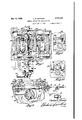
REIOTE CONTROL FOR TRANSMISSIONS Filed July 11, 1938 s Sheets-Sheet 1 Snvcntor flatleslijzbwtd Y attorney Oct. 10, 1939. c. H. STANARD RHIOTE CONTROL FOR TRANSNISSIOiNS Filed July 11, 1959 s sneet -sneet 2 I Gttomegs Oct. 10, 1939. c. H. STANARD 2,175,449
REIOTE CONTROL FOR TRANSMISSIONS Filed July 11, 1938 3 Sheets-Sheet 3 Patented Oct. 1%), 1939 PATENT OFFICE REMOTE CONTROL FOR TRANSMISSIONS Charles H. Stanard, Flint, Mich., assignor to General Motors Corporation, Detroit, Mich, a
corporation of Delaware Application July 11, 1938, Serial No. 218,571 7Claims. (Cl. 74-477) This invention relates to change speed mechanism for motor vehicles and has been designed for changing the gear ratio by manually operable means conveniently located for operation.
5 It provides a so-called remote control wherein novel structural arrangements have been made which constitute the subject matter of this application.
An object of the invention is the avoidance of 10 the conventional shift lever extending from the gear box through the floor of the car body.
A further object is the location adjacent the steering wheel of a manually operable lever which performs the function of the conventional shift 1 lever.
In the accomplishment of the object of the invention certain novel structure has been adopted in the gear box and inthe connection between the manually operable lever and the 20 modification within the gear box.
construction of the mechanism within the gear housing is more particularly the subject matter of this application.
The invention is illustrated by the accom- 25 panying drawings wherein: I
Figure l is a view in side elevation of the assembly used in making gear ratio changes.
Figure 2 is a view as seen from line 2-2 of Figure 1.
3 Figure 3 is a section on line 3-3 of Figure 2.
Figure 4 is a view in elevation adjacent the lower end of the steering column.
Figure 5 is a sectional view as seen from line 55 of Figure .4.
35 Figure 6 is a side elevation facing the side wall of the transmission housing.
Figure 7 is a horizontal section through the top of the gear box.
Figure 8 is a section on line 88 of Figure 7.
I 40 Figure 9 is a section on line 9-3 of Figure '7.
Figure 10 is a section on line of Figure 7. Numeral II shows the frame of a motor vehicle, the engine and the clutch housing being marked l3 and the gear box l5. The hand steer- 45 ing wheel operates a steering post |8 within a fixed steering column |9. Alongside the steering column is a shaft 2| which is mounted to reciprocate and also to rotate on its axis. A lever 23 is used to effect both these movements.
50 As will be explained below, a tilting of the lever serves to-make a selection of .driving ratios and a rocking of the lever about an axis coincident with the axis of the shaft 2| makes the ratio shifts. Adjacent the top of the steering column 55 I9 is a bracket 25 held clamped to the column by The modified securing means 21 and by retaining means 29. The bracket is formed with a spherical socket 3| which serves-as a fulcrum for the tilting and the rocking of lever 23. This hand lever 23 is of channel shape and has a hand grip 33. Its end is shaped as shown in Figure 3 to fit the socket 3|. The lever is held within the socket by a, suitably shaped head 35 of a bolt 31, the shank of which extends through an enlarged opening 32 in the end of the lever 23 an an open- 10 ing in the bracket and is held in position by a nut 39. The enlarged opening 32 permits tilting of the lever. The shank of. the bolt is in alignment with the axis of shaft 2| as shown in Figure 3. Shaft 2| has secured thereto an 15 angular arm 4|. This arm extends between the arms of lever 23 and is pivoted thereto by pivot means 43. A coil spring 45 between the head 35 and the shaft end of arm 4| biases the shaft 2| to its lowermost position. If lever 23 be tilted upwardly it pivots within the socket 3| and since the arm 4| is pivoted to the lever 23 the shaft 2| is moved upwardly against the tension of spring 45.
Adjacent the lower end of the steeringcolumn 85 the shaft 2|- has clamped thereto as at 49 the hub of a lever arm 5|. At the end of the arm there is attached thereto a link 52. A bracket 53 embraces the column near its lower end and below the arm 5| of shaft 2|. This bracket is held by a cap 55 and fastening means 51. The bracket is formed at 58 with a support forthe guidance of shaft 2|. The bracket has two arms 59, 59 serving to journal a bell crank 6| mounted ona pin 63. The bell crank has one arm 65 provided with a bent end 61. The side of the arm and the bent end are provided with rounded l parts 69 which are received within an annular recess 1| near the extreme end of shaft 2|. The bell crank has another arm 13 extending upwardly. The extremity of this arm is reversely bent as at 15 and between the arm and the bent end is pivoted at 13 a block '51 to which is attached the end of a flexible cable 19. The cable extends through a cable housing &|, the latter being anchored to the bracket by any convenient means as shown at 83. v
The novel structure within and adjacent the transmission housing is shown in Figures 7 and 8. The transmission gearing within the housing is not fully illustrated but those parts wherein departure from the conventional has been made are shown and will be described. At the left end of the gear housing is seen a .gear 85 whichgear is on the input shaft. Together with the gear there is shown a frictional clutch element 81 and a jaw clutch element 89. Gear 9| at the other end of the housing is similarly equipped with a friction clutch element 93 and a jaw clutch element 95. As in conventional gearing of this kind gear BI is rotatably supported on an output shaft 91. Slidable on splines of the output shaft 91 is an elongated clutch sleeve 99. This sleeve has at its ends, teeth such as- IIII for engagement with the teeth of jaw clutch 89 and jaw clutch 95. These engagements take place subsequent to the action of conventional synchronizing devices, these being designated by numeral I03. The clutch sleeve 99 has nonrotatably mounted but slidable thereon a gear I05, this gear being adapted to reciprocate to take a low speed drive from the countershaft or to take a reverse drive from a suitable reverse idler driven by the countershaft. From this brief description it will. be seen that sleeve 99 must reciprocate to make shifts from a neutral position to high speed and to second speed. It will also be seen that gear I05 must be reciprocated to make shifts into low and into reverse.
Two shift rails I01 and I09 are provided, these shift rails being slidably mounted in the gear casing. To shift rail I01 is secured the hub portion III) of a shifting arm III engaging a. collar of sleeve 99. Similarly a hub H3 is held to rail It! by fastening means H5 and it carries a fork H2 straddling gear I05. The two rails may be provided with notches I I1 for detent balls to hold them in neutral positions or in driving positions. On adjacent faces of the rails are notches IIS and I2I. On the lower parts of the'rails are grooved recesses I23 and I25. Extending transversely of the gear casing and in the path of movement of the two rails is a shaft I21 which is circular in cross section. This shaft is mounted at its ends-in the gear casing at I29 and I3I. Adjacent each shift rail shaft I21 is formed with annular' grooves I33 and I35. Also'secured to this shaft I21 by fastening means I39 are hubs I and I43 from which project operating arms I44 and I45. These arms are shaped as shown in Figures 9 and 10. They selectively engage the rail notches H9 and I2I. Reciprocation of shaft I21 affects the engagement of one or the other of the arms in its rail notch and rotation of the shaft reciprocates the selected rail. Arm I45 is shaped to give a substantially constant mechanical advantage, whereas arm I44 is shaped to give a changed mechanical advantage between the movement designed to operate the synchronizing clutch and the movement designed to effect the engagement of the'jaw teeth.
-It will be observed from Figure 8 that shaft I21 is within the path of movement of the shift rails as stated above but that one or the other of the rails may reciprocate provided the groove of shaftl21 is adjacent the rail, a position shown at the right hand side of Figure 8. When the position of reciprocation is such as to permit one rail to reciprocate it will be observed that the full diameter portion of shaft I21 is within the notch of the other rail so that said other rail may not reciprocate. This construction is seen at the left side of Figure 8. There is thus provided a very simple and effective interlocking expedient requiring the use of no parts in addition to those used in making the shifts.
tached to the end of the shaft as shown in Figure 8. The end of shaft I21 is recessed and threaded For reciprocating shaft I21 the end of the cable 19 is operably'atthis nut the end of the cable is extended. Within the space between the bottom of the recess and the end of nut I 41 the cable carries an enlargement I49. The cable housing is secured as at I5I to a bracket I53 secured to the transmission casing. By this means the cable may reciprocate the shaft I21 and the rotation of the latter may take place with no interference with the flexible cable. At the-end of shaft I21 adjacent the nut I41 is secured an arm I55 to which is connected, as shown in Figure 8, the end of the link 52 in any convenient or preferred manner. By means of this link axial rotation of shaft 2| rotates lever arm I55 which rotates shaft I21.
It will be understood that the tilting movement of the lever 23 serves to reciprocate shaft 2| and that this reciprocation operating through the flexible cable moves shaft I21 to selectively engage one or the other of the shift rails, the unselected rail being locked from reciprocation by engagement in the recess I23 or I25 as the case may be. Thereafter rotation of lever 23 rotates shaft 2I on its axis and this rotation of shaft 2i operates through the lever and link construction to rotate shaft I21 and thereby reciprocate the selected rail to introduce the desired driving ratio.
I claim:
1. In change speed transmission, a reciprocable rail, means associated with said rail to introduce a plurality of driving ratios, a reciprocable rockshaft extending at right angles to said rail, said rockshaft having an arm to operably engage and reciprocate said rail in response to rockshaft rotation in a selected position of axial reciprocation, said rail having a curvilinear recess to receive a part of said rockshaft in a second position of axial reciprocation of said rockshaft to prevent reciprocation of said rail.
2. In change speed transmission, two parallel reciprocable rails, means associated with said rails for introducing a plurality of driving ratios, a reciprocable rockshaft extending at right angles to said rails, lever arms on said rockshaft adapted to selectively engage said rails as said rockshaft is reciprocated, cooperating pairs of formations rigid with said rails and rockshaft, each pair including a formation on said rockshaft and a formation on one of said rails, the formations of one pair adapted to engage in response to rockshaft reciprocation and constitute interlocking means to lock either rail when the other is to be reciprocated, and means to rock and reciprocate said rockshaft,
3'. In change speed transmission, two parallel reciprocable rails, means associated with said rails for introducing a plurality of driving ratios, a reciprocable rockshaft extendingat right angles to said rails, lever arms on said rockshaft adapted to selectively engage said rails as said rockshaft is reciprocated, formations on said rails and rockshaft constituting interlocking means to lock either rail when the other is to be reciprocated,
I and means to rock and reciprocate said rockshaft,
said interlocking means comprising rounded wall grooves in said rails to selectively receive parts of said rockshaft.
4. In change speed mechanism, shift rails, a
selector shaft extending transversely of said rails,j
prevents reciprocation of said rail, said selector shaft formed with circumferential grooves located adjacent the arms to selectively registerrails and in the path of movement thereof, said v shift rails having grooves wherein said selector shaft is adapted to be selectively received to permit reciprocation of the selector shaft but to prevent reciprocation of one "or the other of the rails. said selector shaft having circumferential grooves to register selectively with said rails whereby one only of said rails may be reciprocated and means on said selector shaft to selectively engage said rails whereby rotation of said selector shaft may reciprocate a selected rail.
7. The invention defined by claim 6, together Gil with'manually operable means to reciprocate and 10 rock said selector shaft.
CHARLES H. STANARD.
Priority Applications (1)
| Application Number | Priority Date | Filing Date | Title |
|---|---|---|---|
| US218571A US2175449A (en) | 1938-07-11 | 1938-07-11 | Remote control for transmissions |
Applications Claiming Priority (1)
| Application Number | Priority Date | Filing Date | Title |
|---|---|---|---|
| US218571A US2175449A (en) | 1938-07-11 | 1938-07-11 | Remote control for transmissions |
Publications (1)
| Publication Number | Publication Date |
|---|---|
| US2175449A true US2175449A (en) | 1939-10-10 |
Family
ID=22815624
Family Applications (1)
| Application Number | Title | Priority Date | Filing Date |
|---|---|---|---|
| US218571A Expired - Lifetime US2175449A (en) | 1938-07-11 | 1938-07-11 | Remote control for transmissions |
Country Status (1)
| Country | Link |
|---|---|
| US (1) | US2175449A (en) |
Cited By (3)
| Publication number | Priority date | Publication date | Assignee | Title |
|---|---|---|---|---|
| US3264895A (en) * | 1963-05-08 | 1966-08-09 | Gen Motors Corp | Control linkage |
| EP0377795A1 (en) * | 1988-12-12 | 1990-07-18 | Dr.Ing.h.c. F. Porsche Aktiengesellschaft | Actuating device for a change-speed gear box |
| US5146806A (en) * | 1989-09-07 | 1992-09-15 | Dr. Ing. H.C.F. Porsche Ag | Shifting arrangement for a gear wheel change box of a motor vehicle |
-
1938
- 1938-07-11 US US218571A patent/US2175449A/en not_active Expired - Lifetime
Cited By (4)
| Publication number | Priority date | Publication date | Assignee | Title |
|---|---|---|---|---|
| US3264895A (en) * | 1963-05-08 | 1966-08-09 | Gen Motors Corp | Control linkage |
| EP0377795A1 (en) * | 1988-12-12 | 1990-07-18 | Dr.Ing.h.c. F. Porsche Aktiengesellschaft | Actuating device for a change-speed gear box |
| US5018404A (en) * | 1988-12-12 | 1991-05-28 | Dr. Ing. H.C.F. Porsche Ag | Control arrangement for a gear shift transmission |
| US5146806A (en) * | 1989-09-07 | 1992-09-15 | Dr. Ing. H.C.F. Porsche Ag | Shifting arrangement for a gear wheel change box of a motor vehicle |
Similar Documents
| Publication | Publication Date | Title |
|---|---|---|
| US1861108A (en) | Integral clutch and transmission control | |
| US4094206A (en) | Gear transmission | |
| US3554047A (en) | Selector mechanisms for change-speed gears | |
| US2861465A (en) | Change speed gear operating system | |
| US2175449A (en) | Remote control for transmissions | |
| US2334421A (en) | Transmission control | |
| US3487713A (en) | Transmission shifting mechanism | |
| US1742749A (en) | Gear-shifting mechanism | |
| US2180579A (en) | Gear shifting mechanism | |
| US2301816A (en) | Transmission shift remotely controlled | |
| US2153085A (en) | Transmission interlock | |
| US2282962A (en) | Gear shift remote control | |
| US2737147A (en) | Transmission control indicator assembly | |
| US4391158A (en) | Biased transmission control shaft | |
| US2317761A (en) | Transmission | |
| US2055770A (en) | Five-speed vehicle transmission | |
| US2171953A (en) | Transmission control | |
| US2195269A (en) | Change speed transmission | |
| RU188504U1 (en) | Drive control of the camshaft transfer case for camshaft with double screw mechanism | |
| US2284191A (en) | Variable speed transmission mechanism | |
| US2182252A (en) | Remote control for transmission | |
| US2231740A (en) | Transmission shifting device | |
| US2503893A (en) | Gear selecting mechanism | |
| US2202949A (en) | Gearshift mechanism | |
| US2029178A (en) | Four-speed vehicle transmission |