US2174183A - Glass-cutting machine - Google Patents
Glass-cutting machine Download PDFInfo
- Publication number
- US2174183A US2174183A US156794A US15679437A US2174183A US 2174183 A US2174183 A US 2174183A US 156794 A US156794 A US 156794A US 15679437 A US15679437 A US 15679437A US 2174183 A US2174183 A US 2174183A
- Authority
- US
- United States
- Prior art keywords
- glass
- strip
- section
- edge
- break
- Prior art date
- Legal status (The legal status is an assumption and is not a legal conclusion. Google has not performed a legal analysis and makes no representation as to the accuracy of the status listed.)
- Expired - Lifetime
Links
Images

Classifications
-
- C—CHEMISTRY; METALLURGY
- C03—GLASS; MINERAL OR SLAG WOOL
- C03B—MANUFACTURE, SHAPING, OR SUPPLEMENTARY PROCESSES
- C03B33/00—Severing cooled glass
- C03B33/10—Glass-cutting tools, e.g. scoring tools
- C03B33/12—Hand tools
-
- Y—GENERAL TAGGING OF NEW TECHNOLOGICAL DEVELOPMENTS; GENERAL TAGGING OF CROSS-SECTIONAL TECHNOLOGIES SPANNING OVER SEVERAL SECTIONS OF THE IPC; TECHNICAL SUBJECTS COVERED BY FORMER USPC CROSS-REFERENCE ART COLLECTIONS [XRACs] AND DIGESTS
- Y10—TECHNICAL SUBJECTS COVERED BY FORMER USPC
- Y10T—TECHNICAL SUBJECTS COVERED BY FORMER US CLASSIFICATION
- Y10T225/00—Severing by tearing or breaking
- Y10T225/30—Breaking or tearing apparatus
- Y10T225/371—Movable breaking tool
Definitions
- an object of the present invention is to provide a simple but efficient means designed to properly start the glass to break at the proper point, said means being adjustable readily to any desired position and hav ing means for fastening it securely in place.
- Another object is to provide detachable and adjustable cutter guides to insure movement of the cutter in the proper direction.
- Figure 1 is a front elevation of the device, the position of the cutter guide when not in use being indicated by broken lines.
- Figure 2 is a section on line 2 27 Figure 1.
- Figure 3 is an elevation of the -device viewed from the left of Figure 1, a portion being broken away.
- Figure 4 is an enlarged section on line d fl, Figure 3.
- Figure 5 is an enlarged section on line 5 5, Figure 1.
- Figure 6 is an enlarged section on line 5 6, Figure 1.
- Figure 7 is a front elevation of the adjustable break starter, adjacent parts being shown partly in section and partly in elevation.
- Figure 8 is an enlarged section on line 8 8, Figure 1.
- Figure 9 is a View similar to Figure 7 but showing a modified form of break starter.
- Figure 10 is a section on line id l, Figure 9.
- Figure 11 is a section on line II II Figure 9.
- Figure 12 is a perspective view of a tool used for gripping the glass to break off narrow strips thereof.
- Figure 13 is a perspective View on .a reduced scale, of a gage which can be used with the machine.
- Section A 5 includes an elongated body strip I having a flat front face to the top portion o f which is secured .
- a cross strip 2 which extends laterally beyond the body I to provide a projecting tongue or extension 3.
- a base strip l Secured to and extending transversely of 10 the bottom portion of body I is a base strip l which extends laterally beyond both sides of the body l, one of these projecting portions forming a tongue 5 of sufficient length to extend across and beyond the adjacent portion of the section B.
- a transverse supporting strip or rest 6 is secured to the bodyrl of section A above and close to the base strip 4 and is adapted to engage the bottom edge of the sheet of glass to be cut s0 as to support the sheet properly in the machine.
- This strip extends laterally beyond the adjacent end of the base strip 4 and is provided at the back thereof, with an upstanding flange 9 flush with the front face of body I and graduated as shown for example in Figure 1, to constitute a 25 measure.
- This flange terminates at the outer side of body I and the graduations forming a ⁇ part of the measure are continued from that point to the inner end of strip 6 upon the top edge of the strip, as shown in Figure 2 at I0.
- the inner end of the rest or supporting strip t terminates inwardly from the inner side of the body I and carries, at an intermediate point, a forwardly projecting block or supplemental rest II which serves as a safety device to prevent glass, which is resting on supporting strip 6 from falling out of the machine should it become dislodged fro-m the top edge of said strip.
- a clamping block Il which engages a fixed screw I3 projecting from body I and is held on the body I by a clamping nut I4 which engages the screw. (See Fig. 7.)
- This nut can be rotated readily by hand and the clamping block I2 is provided for the purpose hereinafter set forth.
- a downwardly and laterally inclined side brace I5 extends back of the projecting tongue 3 and the laterally projecting portion of the strip d and this brace is adjustably fastened to the tongue and strip by means'of bolts I6. It is preferred to extend the bolts through short slots I l for the purpose of facilitating assembly of the parts and effecting any necessary adjustment in order to insure locating the parts in the proper positions relative to each other.
- a measuring rule suitably graduated is arranged along the outer side of the body I as indicated at I8. f
- upper and lower attaching strips I9 and 2! adapted to be attached, by any suitable brackets or the like, not shown, to a supporting structure, such as a wall, frame, or the like.
- a supporting structure such as a wall, frame, or the like.
- a supporting pin 2I having a head or enlargement 22, it being understood that this pin may be formed of a screw or the like.
- the pin is adapted to project into a tongue 23 forming the upwardly extending portion of a hanger 24 the base portion 25 of which is clamped, by a plate 26 and screws 21, to the upper edge portion of a guide strip 28.
- This strip when in operative position, extends downwardly close to the supporting edge of strip 6.
- a nger 29 projects downwardly from strip 28 at the inner side thereof so as to project into the space above the clamping block I2.
- the side edge of this nger provides a continuation of the corresponding edge of the strip 28, the said edge being beveled preferably as shown at 30 and providing a straight guide for a glass cutting tool.
- the tongue 23 has a slot 3
- a fastening plate 33 is fastened to the lower end portion of guide plate 28 and is adapted to lap the adjacent portion of the supporting strip 6.
- This plate has an upstanding flange 34 the forward edge of which is inclined so as to be engaged by a turnbutton 35 rotatably mounted on a plate 36 attached to strip 6. By rotating the turnbutton in one direction, it will release the flange 34 so that the guide strip 28 can be lifted and then moved forwardly for removal from pin 2I. Or, if preferred, the guide strip 28 can be swung laterally out of the way as indicated, for example, by broken lines in Figure l.
- the section B includes a body strip 31 tted snugly against body I and joined thereto by hinges 38 located in the front faces of the body portions I and 31 with their axis of rotation substantially in line with the meeting forward edges of the bodies I and 31.
- the inner side edge of body 31 is slightly beveled, as shown at 39 so that said body 31 thus is permitted to swing backwardly a short distance relative to body I.
- Body 31 is also spaced from the attaching strips I9 and 20 to permit this movement, as shown in FigureZ.
- a top cross strip 40 corresponding with the strip 2 is secured to the front face of body 31 and extends laterally therebeyond to form a .projeoting tongue or ear 4I.
- a supporting or rest strip 42 is secured to the lower portion of the front face of body 31 directly above the laterally projecting portion 5 of base strip 4 and the top edge of this strip 42 alines with the top edge of the strip 6. It terminates a short distance away from the inner side edge of the body 31 and is beveled at this inner end, as indicated at 43.
- An upstanding flange 44 is provided at the back of the strip 42 but terminates at a point removed from the outer side edge of body 31. This flange has been indicated at 44 and is provided with graduations so as to form a measuring rule. The graduations of the rule are continued along the top edge of this strip 42 inwardly from the inner end flange 44, as indicated at 45 in Figure 2.
- Body 31 extends downwardly back of the base strip 4 and has a small portion thereof exposed where the tongue 5 is cut away, as shown at 46. On this exposed portion of body 31 is secured a plate 41 carrying a turnbutton 48 which is adapted normally to lap a wear plate 49 secured on tongue 5, thereby to hold body 31 against swinging movement relative to body I.
- section B is held against spring 1I) or in extreme backward position as shown by broken lines in Fig. 8.
- a downwardly and laterally inclined brace 50 extends back of and is secured to the tongue 4I and the outer end portion of strip 42, this brace being held in place by bolts 5I preferably extended through short slots 52 so that the assembly of the parts can be facilitated and any slight adjustment can be made in order to maintain the parts in proper position relative to each other.
- a pin 53 is removably mounted in one side of brace 52 and is adapted to be transferred to an opening 54 in the front face of the brace when it is desired to support the guide strip 23 in a laterally extended position, as shown by broken lines in Figure 1.
- a wear plate 55 Fastened in a recess in body I adjacent to the upper inner corner portion of supporting strip 6, is a wear plate 55 which can be ush with body I or slightly raised thereabove.
- a flexible breaker including a strip 56 of fibre, leather, or any other suitable material from the upper end of which extends a break starter in the form of an elongated tit 51 the upper end of which is preferably slightly beveled as indicated at 58.
- One side edge of this tit is flush with the corresponding edge of body I.
- One side portion of the plate 55' extends under the clamping block I2 and by tightening the nut I4, this block can be caused to bind upon break plate 55 so as to hold it securely against movement relative to body I. Obviously by loosening the nut the plate and tit 51 can be adjusted to any desired position. While one side edge of the plate 56 extends under block I2, the opposed side edge is tted under the adjacent edge 43 of the strip 42. A stop pin 59 can be used for supporting the lower edge of strip 55 while being placed in position.
- a tool such as shown in Figure 12 and which includes a shank 6l with glass receiving slots S2, is then applied to the edge of the glass and manipulated so as to break olf the narrow edge strip of glass.
- the body l can be provided with a modified form of device including a plate 63 fastened in a recess tl and having in its exposed face a recess 65.
- a groove emanating from the recess E5 is a groove (it the walls of which are undercut so as to retain a strip @l of leather or the like. That portion of the strip nearest the inner side edge of body l can be elevated and slightly beveled as indicated at d8. This elevated portion extends to the inner side edge of body l and acts in the same manner as the glass break-starter heretofore described.
- FIG 13 has been shown a gage to be used when it is desired to cut a number of pieces of glass of the same size.
- This gage, 69 is reversible and either end thereof may be used as a stop.
- this machine can be made either right-hand or left-hand and, under some conditions, the section B can be dispensed with entirely.
- the reason for mounting the tit so that it can be adjusted laterally is to adapt it for use with glass of different thicknesses.
- a stop screw li can be provided in the rest ll where it is in the path of the plate 33 extending from the lower end of the cutter guide so as to permit proper lateral adjustment of the guide relative to the inner edge of the body l.
- the hanger at the upper end of the guide is also adjustable laterally relative thereto as will be apparent by referring to the drawings.
- a glass cutting machine including hingedly connected sections normally flush at the front thereof and contacting along their inner edges, means on the sections for supporting a sheet of glass, a break starter secured to one of the sections and formed of a flexible material, said starter having a beveled portion supported close to and parallel with the edge of the section to which the starter is attached.
- a glass cutting machine including hingedly connected glass supporting sections, means mounted on one of the sections for engaging a sheet of glass at one end of a score therein to support the glass away from the section at the score line and at the meeting edges of the sections, said means constituting a break starter for the glass.
- a glass cutting machine including hingedly connected glass supporting sections, means mounted on one of the sections for engaging a sheet of glass at one end of a score therein tosupport the glass away from the section at the score line and at the meeting edges of the sections, said means constituting a break starter for the glass, and including a flexible member located adjacent to the edges of the sections, and a tit extending from said member and along the edges.
- a glass cutting machine including a section for supporting a sheet of glass, a break starter secured to said section and including a flexible member and a tit extending from the member and along the adjacent edge of the section, said tit and member constituting means for engaging a sheet of glass at one end of a score cut into the glass thereby to start the break in the glass at one end of the score when the glass is bent at the edge of said section.
- a glass cutting machine including a section for supporting a sheet of glass, a break starter secured to said section and including a flexible member and a tit extending from the member and along the adjacent edge of the section, said tit and member constituting means for engaging a sheet of glass at one end of a score cut into the glass thereby to start the break in the glass at one end of the score When the glass is bent at the edge of said section, and a cutter guide detachably secured to the section and positioned to clamp uponv the glass, and means for detachably securing the respective ends of the guide to the section, one of said means constituting a clamp.
Description
Sept. 26, 1939. A, SHAW 2,174,183
GLASS -CUTTING MACHINE Sept. 26, 1939. A. L. sHAw GLASS-GUTTING MACHINE 2 Sheets-.Sheet 2 Filed July 51, 1937 flew L. ,Shaw
INVENTOR.
ATTORNEYS.
Patented Sept. 26, 1939 UNITED STATES PATENT OFFICE GLASS-CUTTING MACHINE. Albert Lemuel Shaw, Corinne, Utah Application July 31, 1937, Serial No. 156,794
5 Claims (Cl. 49-48) This invention relates to means for use in cutting sheet glass and it is designed more especially as an improvement upon the structure disclosed. in Patent 1,961,082, issued to me and Emma J. Shaw on May 29, 1934.
Heretofore in the operation of structures of this type, some difficulty has been experienced in starting the glass to break along the line Where the cut has been made and an object of the present invention is to provide a simple but efficient means designed to properly start the glass to break at the proper point, said means being adjustable readily to any desired position and hav ing means for fastening it securely in place.
Another object is to provide detachable and adjustable cutter guides to insure movement of the cutter in the proper direction.
With the foregoing and other objects in View which will appear as the description proceeds, the invention consists of certain novel details of construction and combinations of parts hereinafter more fully described and pointed out in the claims, it being understood that changes may be made in the construction and arrangement of parts without departing from the spirit of the invention as claimed.
In the accompanying drawings the preferred forms of the invention have been shown.
In said drawings Figure 1 is a front elevation of the device, the position of the cutter guide when not in use being indicated by broken lines.
Figure 2 is a section on line 2 27 Figure 1.
Figure 3 is an elevation of the -device viewed from the left of Figure 1, a portion being broken away.
Figure 4 is an enlarged section on line d fl, Figure 3.
Figure 5 is an enlarged section on line 5 5, Figure 1.
Figure 6 is an enlarged section on line 5 6, Figure 1.
Figure 7 is a front elevation of the adjustable break starter, adjacent parts being shown partly in section and partly in elevation.
Figure 8 is an enlarged section on line 8 8, Figure 1.
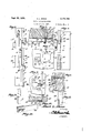
Figure 9 is a View similar to Figure 7 but showing a modified form of break starter.
Figure 10 is a section on line id l, Figure 9.
Figure 11 is a section on line II II Figure 9.
Figure 12 is a perspective view of a tool used for gripping the glass to break off narrow strips thereof.
Figure 13 is a perspective View on .a reduced scale, of a gage which can be used with the machine.
Referring to the gures by characters of reference A and B designate the fixed and movable sections respectively of the machine. Section A 5 includes an elongated body strip I having a flat front face to the top portion o f which is secured .a cross strip 2 which extends laterally beyond the body I to provide a projecting tongue or extension 3. Secured to and extending transversely of 10 the bottom portion of body I is a base strip l which extends laterally beyond both sides of the body l, one of these projecting portions forming a tongue 5 of sufficient length to extend across and beyond the adjacent portion of the section B. 15
A transverse supporting strip or rest 6 is secured to the bodyrl of section A above and close to the base strip 4 and is adapted to engage the bottom edge of the sheet of glass to be cut s0 as to support the sheet properly in the machine. 20 This strip extends laterally beyond the adjacent end of the base strip 4 and is provided at the back thereof, with an upstanding flange 9 flush with the front face of body I and graduated as shown for example in Figure 1, to constitute a 25 measure. This flange terminates at the outer side of body I and the graduations forming a` part of the measure are continued from that point to the inner end of strip 6 upon the top edge of the strip, as shown in Figure 2 at I0. 30
The inner end of the rest or supporting strip t terminates inwardly from the inner side of the body I and carries, at an intermediate point, a forwardly projecting block or supplemental rest II which serves as a safety device to prevent glass, which is resting on supporting strip 6 from falling out of the machine should it become dislodged fro-m the top edge of said strip.
Mounted on the body I in the space provided between the inner end of strip t and the inner side edge of the body I is a clamping block Il which engages a fixed screw I3 projecting from body I and is held on the body I by a clamping nut I4 which engages the screw. (See Fig. 7.) This nut can be rotated readily by hand and the clamping block I2 is provided for the purpose hereinafter set forth.
A downwardly and laterally inclined side brace I5 extends back of the projecting tongue 3 and the laterally projecting portion of the strip d and this brace is adjustably fastened to the tongue and strip by means'of bolts I6. It is preferred to extend the bolts through short slots I l for the purpose of facilitating assembly of the parts and effecting any necessary adjustment in order to insure locating the parts in the proper positions relative to each other.
A measuring rule suitably graduated is arranged along the outer side of the body I as indicated at I8. f
Secured to the back surface of body I are upper and lower attaching strips I9 and 2!) adapted to be attached, by any suitable brackets or the like, not shown, to a supporting structure, such as a wall, frame, or the like. Thus the section A will be held xedly in position for use.
Extending forwardly from the upper portion of the body I is a supporting pin 2I having a head or enlargement 22, it being understood that this pin may be formed of a screw or the like. The pin is adapted to project into a tongue 23 forming the upwardly extending portion of a hanger 24 the base portion 25 of which is clamped, by a plate 26 and screws 21, to the upper edge portion of a guide strip 28. This strip, when in operative position, extends downwardly close to the supporting edge of strip 6. A nger 29 .projects downwardly from strip 28 at the inner side thereof so as to project into the space above the clamping block I2. The side edge of this nger provides a continuation of the corresponding edge of the strip 28, the said edge being beveled preferably as shown at 30 and providing a straight guide for a glass cutting tool.
For the purpose of detachably receiving the holding pin 2|, the tongue 23 has a slot 3| sufficiently wide to receive the head of the pin but this slot merges into a narrower end portion 32 so that when the pin is seated in this narrow portion, the tongue 23 cannot be slipped off of the pin.
A fastening plate 33 is fastened to the lower end portion of guide plate 28 and is adapted to lap the adjacent portion of the supporting strip 6. This plate has an upstanding flange 34 the forward edge of which is inclined so as to be engaged by a turnbutton 35 rotatably mounted on a plate 36 attached to strip 6. By rotating the turnbutton in one direction, it will release the flange 34 so that the guide strip 28 can be lifted and then moved forwardly for removal from pin 2I. Or, if preferred, the guide strip 28 can be swung laterally out of the way as indicated, for example, by broken lines in Figure l.
All of the structure thus far described comprises the section A of the machine. The section B includes a body strip 31 tted snugly against body I and joined thereto by hinges 38 located in the front faces of the body portions I and 31 with their axis of rotation substantially in line with the meeting forward edges of the bodies I and 31. The inner side edge of body 31 is slightly beveled, as shown at 39 so that said body 31 thus is permitted to swing backwardly a short distance relative to body I. Body 31 is also spaced from the attaching strips I9 and 20 to permit this movement, as shown in FigureZ.
A top cross strip 40 corresponding with the strip 2, is secured to the front face of body 31 and extends laterally therebeyond to form a .projeoting tongue or ear 4I. A supporting or rest strip 42 is secured to the lower portion of the front face of body 31 directly above the laterally projecting portion 5 of base strip 4 and the top edge of this strip 42 alines with the top edge of the strip 6. It terminates a short distance away from the inner side edge of the body 31 and is beveled at this inner end, as indicated at 43. An upstanding flange 44 is provided at the back of the strip 42 but terminates at a point removed from the outer side edge of body 31. This flange has been indicated at 44 and is provided with graduations so as to form a measuring rule. The graduations of the rule are continued along the top edge of this strip 42 inwardly from the inner end flange 44, as indicated at 45 in Figure 2.
Body 31 extends downwardly back of the base strip 4 and has a small portion thereof exposed where the tongue 5 is cut away, as shown at 46. On this exposed portion of body 31 is secured a plate 41 carrying a turnbutton 48 which is adapted normally to lap a wear plate 49 secured on tongue 5, thereby to hold body 31 against swinging movement relative to body I. When the nose of the turnbutton is turned upwardly toward tongue 5 and back of plate 43, section B is held against spring 1I) or in extreme backward position as shown by broken lines in Fig. 8.
A downwardly and laterally inclined brace 50 extends back of and is secured to the tongue 4I and the outer end portion of strip 42, this brace being held in place by bolts 5I preferably extended through short slots 52 so that the assembly of the parts can be facilitated and any slight adjustment can be made in order to maintain the parts in proper position relative to each other. A pin 53 is removably mounted in one side of brace 52 and is adapted to be transferred to an opening 54 in the front face of the brace when it is desired to support the guide strip 23 in a laterally extended position, as shown by broken lines in Figure 1.
Fastened in a recess in body I adjacent to the upper inner corner portion of supporting strip 6, is a wear plate 55 which can be ush with body I or slightly raised thereabove. Overlying the lower portion of this plate and extending laterally so as to lap the adjacent portion of the body 31, is a flexible breaker including a strip 56 of fibre, leather, or any other suitable material from the upper end of which extends a break starter in the form of an elongated tit 51 the upper end of which is preferably slightly beveled as indicated at 58. One side edge of this tit is flush with the corresponding edge of body I. (See Fig. 8.) One side portion of the plate 55' extends under the clamping block I2 and by tightening the nut I4, this block can be caused to bind upon break plate 55 so as to hold it securely against movement relative to body I. Obviously by loosening the nut the plate and tit 51 can be adjusted to any desired position. While one side edge of the plate 56 extends under block I2, the opposed side edge is tted under the adjacent edge 43 of the strip 42. A stop pin 59 can be used for supporting the lower edge of strip 55 while being placed in position.
When it is desired to divide a sheet of glass, the same is placed on the strips 6 and 42 so as to rest snugly against bodies I and 31 and forward faces of the braces 'I5 and 50 which are iiush with the corresponding faces of the bodies. The glass will of course be located betweenstrip 6 and the pin 2I. The glass is adjusted so that the severed portion will be correctly measured by the scales both as to width and height. Guide strip 28 is then placed in position and clamped tightly to the glass by means of the button 35 which rides along the inclined edge of flange 34. This guide is shifted by a projecting grip or handle 6G. When the guide is thus located its side edge will be spaced laterally the correct distance from the corresponding edge of body nI and the cutting tool can be moved along the straight edge of guide 28 so as to score the glass along a line corresponding with the meeting edges of the bodies I and 3l. Thereafter the button 43 is turned so as to release body 3l for backward Swinging movement. The user places his thumb on the glass close to the starter and the tips of his ngers on the strip 52. A slight push With the thumb against the glass and section 3l will cause a crack to form in the glass at the point of contact with the tit 5l, and the continued back pressure against body l will cause the glass to gradually become severed along the score therein.
Should it be desired to break off only a narrow strip of glass, the score line in the glass would be brought into register with the outer side edge of body 3l. A tool such as shown in Figure 12 and which includes a shank 6l with glass receiving slots S2, is then applied to the edge of the glass and manipulated so as to break olf the narrow edge strip of glass.
Instead of providing a breaker and tit such as shown at et* and 5l, the body l can be provided with a modified form of device including a plate 63 fastened in a recess tl and having in its exposed face a recess 65. Extending from the recess E5 is a groove (it the walls of which are undercut so as to retain a strip @l of leather or the like. That portion of the strip nearest the inner side edge of body l can be elevated and slightly beveled as indicated at d8. This elevated portion extends to the inner side edge of body l and acts in the same manner as the glass break-starter heretofore described. By providing the recess S5 the breaker El can be slid out of groove S6 when itis desired to remove or replace it.
In Figure 13 has been shown a gage to be used when it is desired to cut a number of pieces of glass of the same size. This gage, 69, is reversible and either end thereof may be used as a stop.
It is to be understood that this machine can be made either right-hand or left-hand and, under some conditions, the section B can be dispensed with entirely.
By providing the plate beneath the tit as shown at 55 in Figure '7, said tit is prevented from eing pressed back into the body l when subjected to excessive pressure during the cutting and breaking operation.
The reason for mounting the tit so that it can be adjusted laterally is to adapt it for use with glass of different thicknesses.
It is to be understood that the two sections A and B are held normally with their front faces flush by means of a spring 'Ill connecting the two sections as shown.
For the purpose of adjusting the cutter guide laterally, a stop screw li can be provided in the rest ll where it is in the path of the plate 33 extending from the lower end of the cutter guide so as to permit proper lateral adjustment of the guide relative to the inner edge of the body l. The hanger at the upper end of the guide is also adjustable laterally relative thereto as will be apparent by referring to the drawings.
What is claimed is:
l. A glass cutting machine including hingedly connected sections normally flush at the front thereof and contacting along their inner edges, means on the sections for supporting a sheet of glass, a break starter secured to one of the sections and formed of a flexible material, said starter having a beveled portion supported close to and parallel with the edge of the section to which the starter is attached.
2. A glass cutting machine including hingedly connected glass supporting sections, means mounted on one of the sections for engaging a sheet of glass at one end of a score therein to support the glass away from the section at the score line and at the meeting edges of the sections, said means constituting a break starter for the glass.
3. A glass cutting machine including hingedly connected glass supporting sections, means mounted on one of the sections for engaging a sheet of glass at one end of a score therein tosupport the glass away from the section at the score line and at the meeting edges of the sections, said means constituting a break starter for the glass, and including a flexible member located adjacent to the edges of the sections, and a tit extending from said member and along the edges.
4. A glass cutting machine including a section for supporting a sheet of glass, a break starter secured to said section and including a flexible member and a tit extending from the member and along the adjacent edge of the section, said tit and member constituting means for engaging a sheet of glass at one end of a score cut into the glass thereby to start the break in the glass at one end of the score when the glass is bent at the edge of said section.
5. A glass cutting machine including a section for supporting a sheet of glass, a break starter secured to said section and including a flexible member and a tit extending from the member and along the adjacent edge of the section, said tit and member constituting means for engaging a sheet of glass at one end of a score cut into the glass thereby to start the break in the glass at one end of the score When the glass is bent at the edge of said section, and a cutter guide detachably secured to the section and positioned to clamp uponv the glass, and means for detachably securing the respective ends of the guide to the section, one of said means constituting a clamp.
ALBERT LEMUEL SHAW.
Priority Applications (1)
| Application Number | Priority Date | Filing Date | Title |
|---|---|---|---|
| US156794A US2174183A (en) | 1937-07-31 | 1937-07-31 | Glass-cutting machine |
Applications Claiming Priority (1)
| Application Number | Priority Date | Filing Date | Title |
|---|---|---|---|
| US156794A US2174183A (en) | 1937-07-31 | 1937-07-31 | Glass-cutting machine |
Publications (1)
| Publication Number | Publication Date |
|---|---|
| US2174183A true US2174183A (en) | 1939-09-26 |
Family
ID=22561117
Family Applications (1)
| Application Number | Title | Priority Date | Filing Date |
|---|---|---|---|
| US156794A Expired - Lifetime US2174183A (en) | 1937-07-31 | 1937-07-31 | Glass-cutting machine |
Country Status (1)
| Country | Link |
|---|---|
| US (1) | US2174183A (en) |
Cited By (6)
| Publication number | Priority date | Publication date | Assignee | Title |
|---|---|---|---|---|
| US2534775A (en) * | 1948-06-16 | 1950-12-19 | Fletcher Terry Co | Glass cutting board |
| US2538901A (en) * | 1949-07-02 | 1951-01-23 | Red Devil Tools | Apparatus for cutting plate glass |
| US2607169A (en) * | 1948-03-22 | 1952-08-19 | Corning Glass Works | Glass severing method and apparatus |
| US2619775A (en) * | 1949-10-01 | 1952-12-02 | Fletcher Terry Co | Glass cutting board |
| US2667691A (en) * | 1951-09-07 | 1954-02-02 | Marton Paul | Glass cutting machine |
| US3305149A (en) * | 1964-08-19 | 1967-02-21 | Triplex Safety Glass Co | Method of and apparatus for breaking out sheets of glass |
-
1937
- 1937-07-31 US US156794A patent/US2174183A/en not_active Expired - Lifetime
Cited By (6)
| Publication number | Priority date | Publication date | Assignee | Title |
|---|---|---|---|---|
| US2607169A (en) * | 1948-03-22 | 1952-08-19 | Corning Glass Works | Glass severing method and apparatus |
| US2534775A (en) * | 1948-06-16 | 1950-12-19 | Fletcher Terry Co | Glass cutting board |
| US2538901A (en) * | 1949-07-02 | 1951-01-23 | Red Devil Tools | Apparatus for cutting plate glass |
| US2619775A (en) * | 1949-10-01 | 1952-12-02 | Fletcher Terry Co | Glass cutting board |
| US2667691A (en) * | 1951-09-07 | 1954-02-02 | Marton Paul | Glass cutting machine |
| US3305149A (en) * | 1964-08-19 | 1967-02-21 | Triplex Safety Glass Co | Method of and apparatus for breaking out sheets of glass |
Similar Documents
| Publication | Publication Date | Title |
|---|---|---|
| US2952025A (en) | Tape measuring guide knife for cutting sheet rock, plaster board and similar materials | |
| US1873721A (en) | Tile scoring and breaking device | |
| US2174183A (en) | Glass-cutting machine | |
| US2287601A (en) | Scriber | |
| US491307A (en) | Pxcture-mat-gutting device | |
| US2814163A (en) | Glass cutting apparatus | |
| US4516712A (en) | Cutting devices for tiles | |
| US4056027A (en) | Cutting device | |
| US869309A (en) | Automatic stop-gage attachment. | |
| US1849493A (en) | Drawing board | |
| US2265955A (en) | Double glass cutter | |
| US1167435A (en) | Trimming-board. | |
| US2287738A (en) | Paper cutter guide | |
| US2205717A (en) | Tile scoring and breaking device | |
| US2591828A (en) | Glass cutting device | |
| US1410196A (en) | Center gauge | |
| US1978787A (en) | Trimming apparatus | |
| US2259117A (en) | Device for holding and cutting sheet material | |
| US2101434A (en) | Vise | |
| US1633196A (en) | Machine for cutting buttonholes | |
| US2619775A (en) | Glass cutting board | |
| US2691810A (en) | Slub-catcher | |
| US1961082A (en) | Glass cutting machine | |
| US1343722A (en) | Fabric-cutting device | |
| US2013216A (en) | Glass holding and breaking device |