US2168564A - Control device - Google Patents
Control device Download PDFInfo
- Publication number
- US2168564A US2168564A US17926A US1792635A US2168564A US 2168564 A US2168564 A US 2168564A US 17926 A US17926 A US 17926A US 1792635 A US1792635 A US 1792635A US 2168564 A US2168564 A US 2168564A
- Authority
- US
- United States
- Prior art keywords
- valve
- bellows
- wall
- evaporator
- casing
- Prior art date
- Legal status (The legal status is an assumption and is not a legal conclusion. Google has not performed a legal analysis and makes no representation as to the accuracy of the status listed.)
- Expired - Lifetime
Links
- 239000003507 refrigerant Substances 0.000 description 16
- NEHMKBQYUWJMIP-UHFFFAOYSA-N chloromethane Chemical compound ClC NEHMKBQYUWJMIP-UHFFFAOYSA-N 0.000 description 8
- 238000004891 communication Methods 0.000 description 4
- 239000012530 fluid Substances 0.000 description 4
- 229940050176 methyl chloride Drugs 0.000 description 4
- 230000006835 compression Effects 0.000 description 3
- 238000007906 compression Methods 0.000 description 3
- 238000001704 evaporation Methods 0.000 description 3
- 230000008020 evaporation Effects 0.000 description 3
- 238000007789 sealing Methods 0.000 description 3
- NEHMKBQYUWJMIP-NJFSPNSNSA-N chloro(114C)methane Chemical compound [14CH3]Cl NEHMKBQYUWJMIP-NJFSPNSNSA-N 0.000 description 2
- 238000001816 cooling Methods 0.000 description 2
- 229920001342 Bakelite® Polymers 0.000 description 1
- 239000004637 bakelite Substances 0.000 description 1
- 238000010276 construction Methods 0.000 description 1
- 239000011810 insulating material Substances 0.000 description 1
- 238000012423 maintenance Methods 0.000 description 1
- 239000000463 material Substances 0.000 description 1
- 239000002184 metal Substances 0.000 description 1
- 210000002445 nipple Anatomy 0.000 description 1
- 238000012856 packing Methods 0.000 description 1
- 238000003466 welding Methods 0.000 description 1
Images
Classifications
-
- G—PHYSICS
- G05—CONTROLLING; REGULATING
- G05D—SYSTEMS FOR CONTROLLING OR REGULATING NON-ELECTRIC VARIABLES
- G05D23/00—Control of temperature
- G05D23/01—Control of temperature without auxiliary power
- G05D23/12—Control of temperature without auxiliary power with sensing element responsive to pressure or volume changes in a confined fluid
Definitions
- One of the objects of our invention is to provide a control device of the thermostatic expansion valve type having a new and improved arrangerncnt of the operating parts thereof.
- Another object of our invention is to provide a new and improved thermostatic expansion valve control device having adjustable operating parts
- the operating parts being so arranged in a casing as to be adjustable without necessity of disassembling the device and in a manner so as to eliminate the necessity of having externally pro- J'ecting adjusting mechanism.
- Another object of our invention is to provide an expansion valve control device having a new and novel means for eliminating noise resulting from operation of the moving parts thereof.
- Another object of our invention is to provide a thermostatic expansion valve control device of the type having metallic bellows for transmitting reciprocal movement to a valve and to provide a device of this character having a new and improved connecting member for the valve and bellows and of a character such that it compensates for inaccuracies in alignment of the valve and bellows to eliminate undue forces opposing free reciprocation of the operating parts.
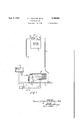
- Figure 1 is a diagrammatic view of a refrigerating system employing our improved control device
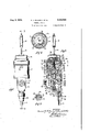
- Fig. 2 is a view shown in side elevation of our thermostatic expansion valve control device embodying features of our invention
- Fig. 3 is a view shown in cross section taken along the line 3-4 of Fig. 2;
- Fig. 4 is a view shown in cross section taken along the line 4-4 of Fig. 3, and
- Fig. 5 is a view shown in cross section taken along the line 5 of Fig. 3.
- the numeral l designates an evaporator r cooling element which may be of the coil type, having a refrigerant medium supply or feed line i 2 and a return or suction line 3.
- the supply line .2 leads from a receiver 4 fed by a condenser 5 "connected to the outlet or discharge side of a compressor 6 to the inlet of which the return line fieads and is connected.
- the compressor may be driven by an electric motor I having the usual condenser cooling fan (not shown).
- the motor is controlled by a pressure switch 8 responsive to variations in pressure in the return line 3 and connected in series circuit in the electric leads 9, H] of the motor thereby to start and stop the motor and therefore the compressor at predetermined desired refrigerant medium pressure tmits.
- a valve H of the thermostatic expansion type which controls the admission of refrigerant medium to the evaporator I.
- the thermostatic expansion valve control device includes a temperature responsive bulb 12 containing or charged with a volatile fluid, such as methyl chloride.
- the bulb i2 is preferably arranged in good heat conductive relation with the outlet or return conduit 3 of the evaporator such as by clamping means l3, Fig. 1, and preferably as close to the evaporator as practicable.
- the bulb I2 is in communication, by means of a tube or conduit M, with a closed chamber I5 of a casing, which casing contains the expansion valve operating mechanism to be hereinafter described.
- the thermostatic expansion valve casing is preferably constructed in sections, including a valve housing section IB and an extension section II fixed to the valve housing.
- the extension sec- 'tion ll, of the sectional casing is constructed of an insulating material, such as Bakelite, and is tubular in shape, having a transverse wall i8 intermediate its ends.
- the tubular extension I! is preferably internally threaded at one end for threading over an externally threaded tubular portion IQ, of the valve housing It, to fix the extension IT to the housing and also so that the circular transverse end wall 20 of the portion l9 provides an offset portion or shoulder relative to the inner wall of the tubular extension ll.
- a pressure responsive means including an expansible-collapsible member 2
- such as a circumferentially corrugated, substantially cylindrical, resilient, metallic bellows, which extends into the tubular section
- the valve housing I6 is provided with an inlet passage 26 and an outlet passage 26 in communication with chamber 24.
- the inlet passage 26, which may be termed the high side of the control device, may be connected to the refrigerant supply conduit 2, such as by means of a fltting or nut 28.
- a strainer member 26 is disposed in inlet passageway 26 and is" supported therein by a nipple ill which in turn is clamped to the valve housing l6 by means of the nut 26.
- the outlet 26 may be connected to the inlet side of the evaporator I, such as by a fltting or nut (not shown), or by any other suitable attaching means. From the chamber 24, refrigerant is drawn through outlet 26 into the evaporator I by the compressor, and the chamber 24 may be termed the low side of the control device.
- valve structure Disposed within the valve casing 16 between the high side and low side of the control device is a valve structure for controlling the admission of refrigerant from the high side to the low side of chamber 24.
- the valve structure includes a ,protuberance or boss 22 which may be an integral portion of the side wall of the casing l6, preferably adjacent the inlet passage 26 as shown, and the boss 62 extends into the casing transversely to the axis or direction of movement of the bellows 2
- a bore 23 In the end portion of the boss 32 is provided a bore 23 in central alignment with the longitudinal axis of bellows 2i and in communication with inlet passageway 26 through a communicating bore 24.
- a tubular member 36 is screw-threaded into bore 62, the other end having a seat for cooperating with the conical face 36 of a needle valve 31.
- the valve 31 and the end of the cup-shaped portion 22 are connected by a yoke or U-shaped bracket 36, the yoke being part of an articulated push rod structure for operating the valve.
- the yoke 66 is provided with an aperture 66 substantially in alignment with the outlet 26 and through which refrigerant leaving the valve port may readily pass unobstructed to the outlet port 26.
- the oppositely disposed sides or arms of the yoke 38 are provided with apertures, the side adjacent the end of the cup-shaped member 23 being rigidly fixed thereto by a post 40 which extends through the aperture in the side and through an aligned aperture in the end wall of the cup-shaped member 23.
- the other side of the yoke 66 receives a threaded retainer member 4! in which the valve TI is fixed.
- a tubular member 42 is threaded over the valve retainer 4
- a temperature responsive power element or actuating member which comprises in general, a cap or housing member 46 and an expansible-collapsible member 46, such as a circumferentially corrugated substantially cylindrical, resilient, metallic bellows.
- a wall member or plate 41 is flxed within the cap 46 preferably adjacent the open end thereof and is formed with a circular flange 46 by means of which it may be fixed to the inner wall of the cap, suchas by welding.
- the plate 41 extends transversely to the side wall of the cap 46 and one end of the bellows 46 is hermetically secured and sealed thereto.
- the other end of the bellows, or free end is closed and sealed by a plate 66.
- the bellows are carried by and within the cap member 46 as an integral part thereof and seal and close the interior of the cap providing the chamber l6 with which the bulb i2 is in communication through the tube l4, as previously described.
- the cap 46 is formed with an outturned circular flange 6
- a detachable wall means or plate 62 Interposed between the circular end wall of the tubular extension I! and the flange 6
- the end of the tubular extension I! adjacent the cap 45 is externally threaded for threaded engagement with an internally threaded ring member or sleeve 63 which surrounds the tubular section and is formed with a circular and in-turned flange 64 on one end for engaging the out-turned flange 6
- packing material may be employed and clamped therebetween to insure a fluid-tight connection.
- the detachable plate or wall 62 is preferably formed centrally thereof with a cup-shaped portion 66 which extends towards the bellows 46 and in the end wall of which is provided an aperture centrally thereof.
- and 46 are connected by an articulated push rod structure which includes a connecting member or nut 66 having one end connected to the closure member or movable and wall 66 of the bellows 46, the other end having a threaded central aperture for receiving the threaded end of a push rod 61, which rod constitutes a section of the articulated push rod structure.
- the connecting member 66 may be rigidly secured to the plate 66 by providing an aperture in the plate for receiving a reduced' end portion of the member 66, the end of which may be peened over to rivet the plate tightly against the shoulder of the connecting member, or the plate and connecting member may be secured together in any other suitable manner.
- the connecting member or nut 66 extends centrally through the bellows 46 and through the aperture in the detachable platev 52, and preferably the aperture in the plate is sufficiently larger than the connecting member 56 to receive and hold a pair of oppositely disposed frictional bearing members 69 under compression against the connecting member 66, to -pre-. vent vibratory movement of the valve, bellows,
- the bearing members 69 may be fixed for movement with the articulated push rod structure by clamping one end of each member between the shoulder of the connecting member 66 and the plate 60 or in any other suitable manner.
- the frictional bearing members 69 are constructed of spring sheet metal and formed having a curved or convex surface.
- the bearing members 69 are preferably arranged so that the convex surface of each is in frictional engagement with the wall defining the aperture in plate 62. 'The other ends of the bearing members frictionally engage the sides of the connecting member 66 and are free to move along the connecting member so that the spring bearin'g members 66 can elongate and contract upon reciprocating engagement with the wall defining the aperture in plate 62.
- the size of the aperture in plate 52 and the curvature of the convex surface of the bearing members 59 are madesuch that when the valve 31 is in closed position, as shown in Fig. 2, the bearing members '59 are under compression although the highest points on their convex surfaces are not in bearing engagement with the wall defining the aperture in plate 52 so that when the valve is opened, the bearing members will be placed under a slightly greater
- the free ends of the bearing members 59 are preferably curved to present a small convex surface at their ends, in engagement with the connecting member 58 so as to reduce friction between the relatively moving parts. It will thus be seen that the'friction bearing members 59 will serve to prevent vibrating movement and resultant noise of the moving valve structure and without appreciably opposing or resisting the free reciprocal movement of the structure.
- the end of the post 40 that extends into the cup shaped portion 23 of the end wall 22 is provided with a central axial bore threaded to receive an externally threaded shank of a socket member 6 i.
- the socket M which receives and retains the ball formed end 62 of the rod 51 may be spun around the ball 62 in the well known manner so that the socket wall retains the ball end of the rod.
- is provided with op-' pcsitely disposed slots lit in its side wall to receive a pin M which extends through an aperture in the ball to prevent rotation of'the rod 51.
- the transverse wall l8 of the extension member ii is provided with a central bore 81 and a counterbore 60 through which extends the rod W of the articulated push rod structure.
- a coil spring 69 is disposed in the chamber 10 between the transverse wall l8 and the plate 52 and surrounds the rod 51 with one end seated in the counterbore 68 and bearing against'wall The other end of spring 69 is positioned in a guide or retainer member 1
- the guide member II and the adjacent end portion of the spring 69 extends into a cup-shaped adjusting member 13 having an open side disposed toward the wall
- the spring 69 is thus held under compression by the adjusting member 13 and acts in a direction tending to close the valve 31.
- the adjusting member 13 hasa central aperture for receiving the rod 51, the aperture being threaded for threaded engagement with the threadedportion or the rod 51.
- the tension of spring 69 may be varied as desired and in the present construction this may be accomplished after the device is assembled by providing an opening 15 leading into chamber 10 giving access to the adjusting member 13.
- the edge deflningfthe open side of the cup-shaped adjusting member 13 may be provided with a series-of spaced notches 18 for receiving a tool insertable through opening 15 to rotate the adjusting member I3.
- a removable closure member or plug Ills provided for closing the opening 15.
- the power element which is a unitary structure may be positioned on the open end of the extension and rotated in a direction such that the connecting member 56 advances on the threaded rod 51 thus collapsing the bellows. After the bellows are completely collapsed, the power element is rotated in the opposite direction until the bellows are opened to the proper working position.
- This position may be determined by the type of thread employed on rod 51 which may be selected such that, say, two turns of the power element will open the bellows to the desired working position. By reason of the arrangement of the parts of the.
- a refrigerating system employing a thermostatic control device or the character described is as follows: With a temperature diiferential of eleven'and one-half degrees Fahrenheit between the temperature of the return or suction line 3 at the evaporator i, the evaporator will be operating at maximum capacity. By maintaining this temperature differential for all evaporator temperatures,” the evaporator will be maintained at maximum capacity and the system at maximum efiiciency. This temperature differential maybe maintained by controlling the admission of refrigerant medium to the evaporator in accordance with the maintenance of the predetermined difierential.
- the evaporator will be at maximum capacity when the temperature of the return line at a point near the evaporator is 25 F.
- the valve 3'! of the thermostatic expansion valve should be seated or closed with the force tending to open the valve balancing the force tending to close the valve, so that if there is any increase in the temperature of the return line 3, and therefore of the bulb l3, at the evaporator, or if there is any decrease in the temperature of evaporation within the evaporator, the valve 31 will be opened to admit refrigerant medium to the evaporator and maintain the desired temperature differential.
- the change in force exerted by the power element for each degree change of temperature must be less than the change in force exerted by the bellows 2
- the pressure or force exerted by the power element at a bulb temperature of 25 F. will be for methyl chloride 17 .5 pounds, as the efiective area of the power element is unity, and the force exertedbythe bellows 2
- the spring 69 is adjusted by the adjusting member 13 to exert a resultant force equal to the difference between the opposing forces, namely, a force of 5.32 pounds acting to seat the valve.
- thermostatic expansion valve having a new and improved arrangement of the operating parts thereof. It will be understood that by providing a separate attaching means for the power element cap 45 that the cap may be rotated to vary the position of the free end of the bellows relative to its fixed end without necessity of removing the cap or otherwise disassembling the device. It will also be seen that we have provided for eliminating noise or rattle of the operating parts of the device. In addition, we have provided a new and improved articulated push rod structure for connecting a bellows to a, valve to prevent side strain between the rod and bellows.
- a casing having an inlet and an outlet and a valve port within the casing, a reciprocal valve within the casing for controlling flow therethrough, a removable cap member mounted on the casing, a bellows carried by said cap member having one end connected thereto and closing and sealing the cap providing a chamber for a volatile fluid within the cap, a detachable plate disposed between the cap member and the casing and having an opening therethrough, means for clamping the cap and.
- a casing having an inlet and an outlet and having a valve port therewithin, a reciprocal valve within said casing for controlling flow through said valve port, a removable cap member mounted on said casing, movable wall means carried by said cap member, said movable wall means sealing said cap member and cooperating therewith to provide a chamber for an expansible-contractible fluid operable for moving said movable wall means, a detachable wall means disposed between said cap member and said casing and having an opening therethrough, a clamping ring for securing said cap member and said detachable wall means together and to said casing, a connecting member in said casing having one and connected to said valve and the other end extending through the opening in said detachable wall means and connected to said movable wall means, and a rein a wall thereof, a bellows member closing and I sealing said opening and cooperating with the inner walls of said body to provide.
- a pressure chamber in which the pressure of a fluid acts on the bellows member
- an open ended tubular extension having one end secured to said body and surrounding said bellows member, temperature responsive means mounted on the other end of said extension and including a bellows member opposed to said first-named bellows member, said extension having an internal transverse wall intermediate its ends between said bellows members and cooperating therewith to provide a chamber .on each side of the transverse wall, said transverse wall having an aperture therethrough, a thrust member operatively connecting said bellows members and said valve member and extending through said aperture, an abutment member adjustably supported on said thrust member in the chamber between said transverse wall and said second-named bellows, and a coil spring in said last-named chamber bearing against said abutment member and said internal wall, said spring acting-with one of said bellows members and opposing the other of said bellows members.
- a cas- 15 securing said removable cap member and said removable wall member to said casing, a thrust member within said casing operatively connecting the free end of said bellows member and said valve and extending through the said opening in said removable wall member, spring means operable to actuate said valve, and a spring bearing member carried by said thrust member and engaging the wall deflning the opening in said removable wall member to dampen vibrating move- 1 ment of 'said valve.
Landscapes
- Physics & Mathematics (AREA)
- General Physics & Mathematics (AREA)
- Engineering & Computer Science (AREA)
- Automation & Control Theory (AREA)
- Temperature-Responsive Valves (AREA)
Description
1939. E. J. DILLMAN ET AL 2,168,564
CONTROL DEVICE Filed April 24, 1955 2 Sheets-Sheet 2 m/M 1. ew' fislwa wk Patented Aug; 8, 1939 CONTROL nEvIcE Earnest J. Dillman and Daniel D. Wile, Detroit,
Mich., assignors to Detroit Lubricator Company, Detroit, Mich., a corporation of Michig an Application April 24, 1935, Serial No. 17,926
4 Claims. (Cl. 236-92) Our invention relates to new and useful improvements in control devices, and more particularly to control devices of the thermostatic expansion valve type.
One of the objects of our invention is to provide a control device of the thermostatic expansion valve type having a new and improved arrangerncnt of the operating parts thereof.
Another object of our invention is to provide a new and improved thermostatic expansion valve control device having adjustable operating parts,
the operating parts being so arranged in a casing as to be adjustable without necessity of disassembling the device and in a manner so as to eliminate the necessity of having externally pro- J'ecting adjusting mechanism.
Another object of our invention is to provide an expansion valve control device having a new and novel means for eliminating noise resulting from operation of the moving parts thereof.
Another object of our invention is to provide a thermostatic expansion valve control device of the type having metallic bellows for transmitting reciprocal movement to a valve and to provide a device of this character having a new and improved connecting member for the valve and bellows and of a character such that it compensates for inaccuracies in alignment of the valve and bellows to eliminate undue forces opposing free reciprocation of the operating parts.
In the accompanying drawings, to be taken a part of this specification, we have fully and clearly illustrated a preferred embodiment of our invention, in which drawings:
Figure 1 is a diagrammatic view of a refrigerating system employing our improved control device;
, Fig. 2 is a view shown in side elevation of our thermostatic expansion valve control device embodying features of our invention;
Fig. 3 is a view shown in cross section taken along the line 3-4 of Fig. 2;
Fig. 4 is a view shown in cross section taken along the line 4-4 of Fig. 3, and
Fig. 5 is a view shown in cross section taken along the line 5 of Fig. 3.
Referring to the drawings by characters of reference, the numeral l designates an evaporator r cooling element which may be of the coil type, having a refrigerant medium supply or feed line i 2 and a return or suction line 3. The supply line .2 leads from a receiver 4 fed by a condenser 5 "connected to the outlet or discharge side of a compressor 6 to the inlet of which the return line fieads and is connected. The compressor may be driven by an electric motor I having the usual condenser cooling fan (not shown). The motor is controlled by a pressure switch 8 responsive to variations in pressure in the return line 3 and connected in series circuit in the electric leads 9, H] of the motor thereby to start and stop the motor and therefore the compressor at predetermined desired refrigerant medium pressure tmits. In the supply conduit 2 is. a valve H of the thermostatic expansion type which controls the admission of refrigerant medium to the evaporator I. Referring now to the control device which is shown in detail in Fig. 2, the thermostatic expansion valve control device includes a temperature responsive bulb 12 containing or charged with a volatile fluid, such as methyl chloride. and when the control device is in opera tive position with the refrigerating system, the bulb i2 is preferably arranged in good heat conductive relation with the outlet or return conduit 3 of the evaporator such as by clamping means l3, Fig. 1, and preferably as close to the evaporator as practicable. The bulb I2 is in communication, by means of a tube or conduit M, with a closed chamber I5 of a casing, which casing contains the expansion valve operating mechanism to be hereinafter described. As shown, the thermostatic expansion valve casing is preferably constructed in sections, including a valve housing section IB and an extension section II fixed to the valve housing. Preferably the extension sec- 'tion ll, of the sectional casing, is constructed of an insulating material, such as Bakelite, and is tubular in shape, having a transverse wall i8 intermediate its ends. The tubular extension I! is preferably internally threaded at one end for threading over an externally threaded tubular portion IQ, of the valve housing It, to fix the extension IT to the housing and also so that the circular transverse end wall 20 of the portion l9 provides an offset portion or shoulder relative to the inner wall of the tubular extension ll.
Secured and sealed to the transverse circular end wall 20 of the valve housing is a pressure responsive means including an expansible-collapsible member 2|, such as a circumferentially corrugated, substantially cylindrical, resilient, metallic bellows, which extends into the tubular section |'l towards the transverse wall i8 thereof.- Secured and hermetically sealed tothe free end of the bellows 2|, which end is disposed toward the wall ll of the tubular extension I1, is a cupshaped head or end wall 22, the cup-shaped portion 23 of which extends centrally through the bellows 2| and into the valve housing It. The
bellows 2i and the cup-shaped end wall 22, closing the free end of the bellows, thus cooperate to close and seal the valve housing from the interior of the tubular extension, providing a closed chamber 24 within the valve housing l6.
The valve housing I6 is provided with an inlet passage 26 and an outlet passage 26 in communication with chamber 24. The inlet passage 26, which may be termed the high side of the control device, may be connected to the refrigerant supply conduit 2, such as by means of a fltting or nut 28. A strainer member 26 is disposed in inlet passageway 26 and is" supported therein by a nipple ill which in turn is clamped to the valve housing l6 by means of the nut 26. The outlet 26 may be connected to the inlet side of the evaporator I, such as by a fltting or nut (not shown), or by any other suitable attaching means. From the chamber 24, refrigerant is drawn through outlet 26 into the evaporator I by the compressor, and the chamber 24 may be termed the low side of the control device.
Disposed within the valve casing 16 between the high side and low side of the control device is a valve structure for controlling the admission of refrigerant from the high side to the low side of chamber 24. The valve structure includes a ,protuberance or boss 22 which may be an integral portion of the side wall of the casing l6, preferably adjacent the inlet passage 26 as shown, and the boss 62 extends into the casing transversely to the axis or direction of movement of the bellows 2|. In the end portion of the boss 32 is provided a bore 23 in central alignment with the longitudinal axis of bellows 2i and in communication with inlet passageway 26 through a communicating bore 24. One end of a tubular member 36 is screw-threaded into bore 62, the other end having a seat for cooperating with the conical face 36 of a needle valve 31. The valve 31 and the end of the cup-shaped portion 22 are connected by a yoke or U-shaped bracket 36, the yoke being part of an articulated push rod structure for operating the valve. Preferably the yoke 66 is provided with an aperture 66 substantially in alignment with the outlet 26 and through which refrigerant leaving the valve port may readily pass unobstructed to the outlet port 26. The oppositely disposed sides or arms of the yoke 38 are provided with apertures, the side adjacent the end of the cup-shaped member 23 being rigidly fixed thereto by a post 40 which extends through the aperture in the side and through an aligned aperture in the end wall of the cup-shaped member 23. The other side of the yoke 66 receives a threaded retainer member 4! in which the valve TI is fixed. A tubular member 42 is threaded over the valve retainer 4| and is arranged for reciprocal movement in a guide 42 which is threaded in the wall of the casing I6.
On the other end of the tubular section I1 is mounted a temperature responsive power element or actuating member which comprises in general, a cap or housing member 46 and an expansible-collapsible member 46, such as a circumferentially corrugated substantially cylindrical, resilient, metallic bellows. A wall member or plate 41 is flxed within the cap 46 preferably adjacent the open end thereof and is formed with a circular flange 46 by means of which it may be fixed to the inner wall of the cap, suchas by welding. The plate 41 extends transversely to the side wall of the cap 46 and one end of the bellows 46 is hermetically secured and sealed thereto. The other end of the bellows, or free end, is closed and sealed by a plate 66. Thus, the bellows are carried by and within the cap member 46 as an integral part thereof and seal and close the interior of the cap providing the chamber l6 with which the bulb i2 is in communication through the tube l4, as previously described.
Preferably the cap 46 is formed with an outturned circular flange 6| for bearing against the circular end wall of the tubular extension i1 and for clamping the cap 46 thereto. Interposed between the circular end wall of the tubular extension I! and the flange 6| of the'cap is a detachable wall means or plate 62. The end of the tubular extension I! adjacent the cap 45 is externally threaded for threaded engagement with an internally threaded ring member or sleeve 63 which surrounds the tubular section and is formed with a circular and in-turned flange 64 on one end for engaging the out-turned flange 6| of the cap 46 to clamp the same to the tubular section II. Between the cap 46 and the plate 62 and between the plate 52 and the circular end wall of the tubular section II, packing material may be employed and clamped therebetween to insure a fluid-tight connection.
The detachable plate or wall 62 is preferably formed centrally thereof with a cup-shaped portion 66 which extends towards the bellows 46 and in the end wall of which is provided an aperture centrally thereof.' The valve 31 and the free ends of the bellows 2| and 46 are connected by an articulated push rod structure which includes a connecting member or nut 66 having one end connected to the closure member or movable and wall 66 of the bellows 46, the other end having a threaded central aperture for receiving the threaded end of a push rod 61, which rod constitutes a section of the articulated push rod structure. The connecting member 66 may be rigidly secured to the plate 66 by providing an aperture in the plate for receiving a reduced' end portion of the member 66, the end of which may be peened over to rivet the plate tightly against the shoulder of the connecting member, or the plate and connecting member may be secured together in any other suitable manner.
The connecting member or nut 66 extends centrally through the bellows 46 and through the aperture in the detachable platev 52, and preferably the aperture in the plate is sufficiently larger than the connecting member 56 to receive and hold a pair of oppositely disposed frictional bearing members 69 under compression against the connecting member 66, to -pre-. vent vibratory movement of the valve, bellows,
and articulated push rod structure. The bearing members 69 may be fixed for movement with the articulated push rod structure by clamping one end of each member between the shoulder of the connecting member 66 and the plate 60 or in any other suitable manner. Preferably the frictional bearing members 69 are constructed of spring sheet metal and formed having a curved or convex surface. The bearing members 69 are preferably arranged so that the convex surface of each is in frictional engagement with the wall defining the aperture in plate 62. 'The other ends of the bearing members frictionally engage the sides of the connecting member 66 and are free to move along the connecting member so that the spring bearin'g members 66 can elongate and contract upon reciprocating engagement with the wall defining the aperture in plate 62. I6
Preferably the size of the aperture in plate 52 and the curvature of the convex surface of the bearing members 59 are madesuch that when the valve 31 is in closed position, as shown in Fig. 2, the bearing members '59 are under compression although the highest points on their convex surfaces are not in bearing engagement with the wall defining the aperture in plate 52 so that when the valve is opened, the bearing members will be placed under a slightly greater The free ends of the bearing members 59 are preferably curved to present a small convex surface at their ends, in engagement with the connecting member 58 so as to reduce friction between the relatively moving parts. It will thus be seen that the'friction bearing members 59 will serve to prevent vibrating movement and resultant noise of the moving valve structure and without appreciably opposing or resisting the free reciprocal movement of the structure.
Y The end of the post 40 that extends into the cup shaped portion 23 of the end wall 22 is provided with a central axial bore threaded to receive an externally threaded shank of a socket member 6 i. The socket M which receives and retains the ball formed end 62 of the rod 51 may be spun around the ball 62 in the well known manner so that the socket wall retains the ball end of the rod. Preferably the socket 6| is provided with op-' pcsitely disposed slots lit in its side wall to receive a pin M which extends through an aperture in the ball to prevent rotation of'the rod 51. It will thus be seen that by providing an articulated push rod structure, having a ball and socket connection, for operatively connecting the bellows and valve that inaccuracies in alignment of the bellowsand valve, or inaccuracies in the bellows which would cause them to move in a line not concentric with each other or with the guided reciprocating valve 31 will be compensated for, to eliminate opposing forces to the free movement of the parts which would otherwise be present.
The transverse wall l8 of the extension member ii is provided with a central bore 81 and a counterbore 60 through which extends the rod W of the articulated push rod structure. A coil spring 69 is disposed in the chamber 10 between the transverse wall l8 and the plate 52 and surrounds the rod 51 with one end seated in the counterbore 68 and bearing against'wall The other end of spring 69 is positioned in a guide or retainer member 1| having an aperture 'for receiving the ,rod 51, the aperture being sufilciently large to permit free movement of the rod 51 therethrough without interference. The guide member II and the adjacent end portion of the spring 69 extends into a cup-shaped adjusting member 13 having an open side disposed toward the wall |8 of the extension member II. The spring 69 is thus held under compression by the adjusting member 13 and acts in a direction tending to close the valve 31. I The adjusting member 13 hasa central aperture for receiving the rod 51, the aperture being threaded for threaded engagement with the threadedportion or the rod 51. By rotating the adjusting member I3 on the rod 51, the tension of spring 69 may be varied as desired and in the present construction this may be accomplished after the device is assembled by providing an opening 15 leading into chamber 10 giving access to the adjusting member 13. As shown in Fig. 4, the edge deflningfthe open side of the cup-shaped adjusting member 13 may be provided with a series-of spaced notches 18 for receiving a tool insertable through opening 15 to rotate the adjusting member I3. Preferably a removable closure member or plug Ills provided for closing the opening 15.
When assemblingthe control device, the power element which is a unitary structure may be positioned on the open end of the extension and rotated in a direction such that the connecting member 56 advances on the threaded rod 51 thus collapsing the bellows. After the bellows are completely collapsed, the power element is rotated in the opposite direction until the bellows are opened to the proper working position. This position may be determined by the type of thread employed on rod 51 which may be selected such that, say, two turns of the power element will open the bellows to the desired working position. By reason of the arrangement of the parts of the. power element as a unitary structure so that the bellows may be expanded or collapsed through rotation of the cap, it will be appreciated that-adjustment may be made after the bellows are enclosed and without the necessity of externally projecting adjusting mechanism. After the bellows have been properly positioned, the clamping ring is threaded to the tubular extension Ill and the cap 45 tightly clamped thereby to the casing;
The operation of a refrigerating system employing a thermostatic control device or the character described is as follows: With a temperature diiferential of eleven'and one-half degrees Fahrenheit between the temperature of the return or suction line 3 at the evaporator i, the evaporator will be operating at maximum capacity. By maintaining this temperature differential for all evaporator temperatures," the evaporator will be maintained at maximum capacity and the system at maximum efiiciency. This temperature differential maybe maintained by controlling the admission of refrigerant medium to the evaporator in accordance with the maintenance of the predetermined difierential. refrigerant medium employed is methyl chloride, then with evaporation of the refrigerant medium in the evaporator occurring at say, 13.5 F., the evaporator" will be at maximum capacity when the temperature of the return line at a point near the evaporator is 25 F. At these temperatures the valve 3'! of the thermostatic expansion valve should be seated or closed with the force tending to open the valve balancing the force tending to close the valve, so that if there is any increase in the temperature of the return line 3, and therefore of the bulb l3, at the evaporator, or if there is any decrease in the temperature of evaporation within the evaporator, the valve 31 will be opened to admit refrigerant medium to the evaporator and maintain the desired temperature differential. In order to maintain this differential for all operating temperatures of the evaporator, the change in force exerted by the power element for each degree change of temperature must be less than the change in force exerted by the bellows 2| and ii, for example, the ratio in square inches of the effective areas of the power element and the bellows 2| is as 1.00 to 1.16, then the desired temperature differential will be maintained for methyl chloride refrigerant. The pressure or force exerted by the power element at a bulb temperature of 25 F., will be for methyl chloride 17 .5 pounds, as the efiective area of the power element is unity, and the force exertedbythe bellows 2| will be in accordance with the temperature of 1 evaporation of the refrigerant in the evaporator,
which at 13.5 F., is 10.5 pounds per square inch If, for example, the
for methyl chloride, so that the force exerted by bellows 2| tending to close the valve 31 will be 12.18 pounds. Therefore in order to have the valve in balanced closed position, the spring 69 is adjusted by the adjusting member 13 to exert a resultant force equal to the difference between the opposing forces, namely, a force of 5.32 pounds acting to seat the valve.
When the system is started in operation from a warm condition by closing of the circuit of motor I, with the temperature of the bulb [2 at say 80 F., the force exerted by the power element will be 71.75 pounds acting through the articulated push rod structure and tending to open the valve 31'. In order that the evaporator may be operating at maximum capacity at this starting temperature, there should be a differential of 115 F., or the temperature in .the evaporator should be 685 R, which corresponds to a refrigerant medium pressure with methyl chloride of 57.2 pounds per square inch. This force acting through the bellows 2| to close valve 31 will, due to the effective areas of bellows H, be exerting a force on the push rod structure of 66.43 pounds, which added to the force exerted by the spring 69 of 5.32 pounds equals 71.75 pounds, so that the valve is held in balanced closed position. when the compressor reduces the pressure in the evaporator below 57.2 pounds per square inch, the power element being subject to a temperature of 80 F., will act to open valve 31 to admit refrigerant medium to the evaporator, the medium expanding therein to increase the pressure and close the valve. This will, however, decrease the temperature of the return line and therefore of the bulb l3, so that the pressure in the evaporator may be further reduced by the compressor before the valve 31 will be opened. This gradual step by step reduction of pressure while maintaining a substantially constant temperature differential will continue until the low pressure limit is reached, corresponding to a temperature of, say, 25' F., at the bulb l3, when the switch 8 will stop the motor and compressor. As the bulb l3 warms, tending to open valve 31, the refrigerant medium in the evaporator will also expand to increase the evaporator pressure which acting through bellows 2l will prevent the valve from opening. The temperature of the evaporator increases until the predetermined desired maximum pressure in the return line is reached, when switch 8 will again turn on the motor i to complete a cycle of operation and start a decrease of evaporator temperature.
From the foregoing description, it will be seen that we have provided a thermostatic expansion valve having a new and improved arrangement of the operating parts thereof. It will be understood that by providing a separate attaching means for the power element cap 45 that the cap may be rotated to vary the position of the free end of the bellows relative to its fixed end without necessity of removing the cap or otherwise disassembling the device. It will also be seen that we have provided for eliminating noise or rattle of the operating parts of the device. In addition, we have provided a new and improved articulated push rod structure for connecting a bellows to a, valve to prevent side strain between the rod and bellows.
What we claim and desire to secure by Letters Patent'of the United States is:
1. In a device of the character described, a casing having an inlet and an outlet and a valve port within the casing, a reciprocal valve within the casing for controlling flow therethrough, a removable cap member mounted on the casing, a bellows carried by said cap member having one end connected thereto and closing and sealing the cap providing a chamber for a volatile fluid within the cap, a detachable plate disposed between the cap member and the casing and having an opening therethrough, means for clamping the cap and. plate to the casing, an articulated push rod structure within the casing connecting the free end of the bellows and said valve, one end of said rod extending through said opening in said plate, a resilient bearing member cooperable with said plate and said rod and frictionally opposing movement of said rod through said plate opening, a spring in said casing surrounding saidrod and acting to close said valve, and means carried by said rod and within the casing for adjusting the tension of said spring.
2. In a device of the character described, a casing having an inlet and an outlet and having a valve port therewithin, a reciprocal valve within said casing for controlling flow through said valve port, a removable cap member mounted on said casing, movable wall means carried by said cap member, said movable wall means sealing said cap member and cooperating therewith to provide a chamber for an expansible-contractible fluid operable for moving said movable wall means, a detachable wall means disposed between said cap member and said casing and having an opening therethrough, a clamping ring for securing said cap member and said detachable wall means together and to said casing, a connecting member in said casing having one and connected to said valve and the other end extending through the opening in said detachable wall means and connected to said movable wall means, and a rein a wall thereof, a bellows member closing and I sealing said opening and cooperating with the inner walls of said body to provide. a pressure chamber in which the pressure of a fluid acts on the bellows member, an open ended tubular extension having one end secured to said body and surrounding said bellows member, temperature responsive means mounted on the other end of said extension and including a bellows member opposed to said first-named bellows member, said extension having an internal transverse wall intermediate its ends between said bellows members and cooperating therewith to provide a chamber .on each side of the transverse wall, said transverse wall having an aperture therethrough, a thrust member operatively connecting said bellows members and said valve member and extending through said aperture, an abutment member adjustably supported on said thrust member in the chamber between said transverse wall and said second-named bellows, and a coil spring in said last-named chamber bearing against said abutment member and said internal wall, said spring acting-with one of said bellows members and opposing the other of said bellows members.
4. In a device of the character described, a cas- 15 securing said removable cap member and said removable wall member to said casing, a thrust member within said casing operatively connecting the free end of said bellows member and said valve and extending through the said opening in said removable wall member, spring means operable to actuate said valve, and a spring bearing member carried by said thrust member and engaging the wall deflning the opening in said removable wall member to dampen vibrating move- 1 ment of 'said valve.
' EARNEST J. DILLMAN.
DANIEL D. WILE.
Priority Applications (1)
| Application Number | Priority Date | Filing Date | Title |
|---|---|---|---|
| US17926A US2168564A (en) | 1935-04-24 | 1935-04-24 | Control device |
Applications Claiming Priority (1)
| Application Number | Priority Date | Filing Date | Title |
|---|---|---|---|
| US17926A US2168564A (en) | 1935-04-24 | 1935-04-24 | Control device |
Publications (1)
| Publication Number | Publication Date |
|---|---|
| US2168564A true US2168564A (en) | 1939-08-08 |
Family
ID=21785304
Family Applications (1)
| Application Number | Title | Priority Date | Filing Date |
|---|---|---|---|
| US17926A Expired - Lifetime US2168564A (en) | 1935-04-24 | 1935-04-24 | Control device |
Country Status (1)
| Country | Link |
|---|---|
| US (1) | US2168564A (en) |
-
1935
- 1935-04-24 US US17926A patent/US2168564A/en not_active Expired - Lifetime
Similar Documents
| Publication | Publication Date | Title |
|---|---|---|
| US2471448A (en) | Built-in heat exchanger in expansion valve structure | |
| US2289905A (en) | Refrigerating apparatus | |
| US3324673A (en) | Refrigeration system with check valve | |
| US2856759A (en) | Refrigerating evaporative apparatus | |
| US2192117A (en) | Control device | |
| US2259280A (en) | Control device | |
| US2209216A (en) | Control device | |
| US2755025A (en) | Refrigeration expansion valve apparatus | |
| US2475556A (en) | Refrigeration system, including valve controls | |
| US2215947A (en) | Refrigerating apparatus | |
| US2116802A (en) | Refrigeration control apparatus | |
| US1987948A (en) | Refrigerant control device | |
| US2415338A (en) | Refrigeration system and expansion valve therefor | |
| US2967403A (en) | Constant pressure expansion valve | |
| US2168564A (en) | Control device | |
| US2520386A (en) | Refrigeration expansion valve | |
| US2410795A (en) | Expansion valve | |
| US3715894A (en) | Air conditioning bypass control | |
| US2363010A (en) | Refrigerant control system | |
| US2152781A (en) | Control device | |
| US2319993A (en) | Refrigerating apparatus | |
| US3498074A (en) | Control system for refrigerating apparatus | |
| US2160453A (en) | Refrigerating apparatus | |
| US2542802A (en) | Thermostatic expansion valve with adjustable pressure limiting feature | |
| US2224377A (en) | Refrigerating apparatus |