US2160271A - Automobile - Google Patents
Automobile Download PDFInfo
- Publication number
- US2160271A US2160271A US186290A US18629038A US2160271A US 2160271 A US2160271 A US 2160271A US 186290 A US186290 A US 186290A US 18629038 A US18629038 A US 18629038A US 2160271 A US2160271 A US 2160271A
- Authority
- US
- United States
- Prior art keywords
- engine
- wheels
- section
- wheel
- axle
- Prior art date
- Legal status (The legal status is an assumption and is not a legal conclusion. Google has not performed a legal analysis and makes no representation as to the accuracy of the status listed.)
- Expired - Lifetime
Links
- 230000005540 biological transmission Effects 0.000 description 21
- 238000010276 construction Methods 0.000 description 18
- 230000000694 effects Effects 0.000 description 12
- 238000006243 chemical reaction Methods 0.000 description 9
- 230000002441 reversible effect Effects 0.000 description 6
- 239000000725 suspension Substances 0.000 description 6
- 230000000875 corresponding effect Effects 0.000 description 5
- 230000001133 acceleration Effects 0.000 description 4
- 238000003466 welding Methods 0.000 description 4
- 229910000831 Steel Inorganic materials 0.000 description 3
- 239000002184 metal Substances 0.000 description 3
- 239000010959 steel Substances 0.000 description 3
- 230000006835 compression Effects 0.000 description 2
- 238000007906 compression Methods 0.000 description 2
- 230000008030 elimination Effects 0.000 description 2
- 238000003379 elimination reaction Methods 0.000 description 2
- 239000000945 filler Substances 0.000 description 2
- 230000007935 neutral effect Effects 0.000 description 2
- 230000000750 progressive effect Effects 0.000 description 2
- 230000003014 reinforcing effect Effects 0.000 description 2
- 241000239290 Araneae Species 0.000 description 1
- 238000013459 approach Methods 0.000 description 1
- 230000000712 assembly Effects 0.000 description 1
- 238000000429 assembly Methods 0.000 description 1
- 230000003190 augmentative effect Effects 0.000 description 1
- 230000015572 biosynthetic process Effects 0.000 description 1
- 230000001427 coherent effect Effects 0.000 description 1
- 150000001875 compounds Chemical class 0.000 description 1
- 230000007423 decrease Effects 0.000 description 1
- 238000013461 design Methods 0.000 description 1
- 230000003467 diminishing effect Effects 0.000 description 1
- 210000000887 face Anatomy 0.000 description 1
- 239000002828 fuel tank Substances 0.000 description 1
- 239000003502 gasoline Substances 0.000 description 1
- 230000005484 gravity Effects 0.000 description 1
- 210000003128 head Anatomy 0.000 description 1
- 230000002452 interceptive effect Effects 0.000 description 1
- 238000000034 method Methods 0.000 description 1
- 238000012856 packing Methods 0.000 description 1
- 230000002787 reinforcement Effects 0.000 description 1
- 238000000926 separation method Methods 0.000 description 1
- 230000035939 shock Effects 0.000 description 1
- 238000013022 venting Methods 0.000 description 1
- 238000009941 weaving Methods 0.000 description 1
- 239000002023 wood Substances 0.000 description 1
Images


Classifications
-
- B—PERFORMING OPERATIONS; TRANSPORTING
- B60—VEHICLES IN GENERAL
- B60K—ARRANGEMENT OR MOUNTING OF PROPULSION UNITS OR OF TRANSMISSIONS IN VEHICLES; ARRANGEMENT OR MOUNTING OF PLURAL DIVERSE PRIME-MOVERS IN VEHICLES; AUXILIARY DRIVES FOR VEHICLES; INSTRUMENTATION OR DASHBOARDS FOR VEHICLES; ARRANGEMENTS IN CONNECTION WITH COOLING, AIR INTAKE, GAS EXHAUST OR FUEL SUPPLY OF PROPULSION UNITS IN VEHICLES
- B60K17/00—Arrangement or mounting of transmissions in vehicles
- B60K17/30—Arrangement or mounting of transmissions in vehicles the ultimate propulsive elements, e.g. ground wheels, being steerable
- B60K17/306—Arrangement or mounting of transmissions in vehicles the ultimate propulsive elements, e.g. ground wheels, being steerable with a universal joint in the axis of the steering knuckle
Definitions
- This invention relates to automobiles and other motor vehicles, and is illustrated as embodied in an automobile having a novel arrangement of parts giving a very light weight and consequent high acceleration, and which is of simple and inexpensive construction and which is preferably of the front-wheel drive variety.
- One feature of the invention relates to the construction of the vehicle in two sections, shown as being respectively afront section carrying the power plant and a rear section shown as being a sort of trailer unit which carries the body and which is attached in a novel manner to the front section. Since practically all the operating parts of the vehicle are on the front section, this permits a very simple and inexpensive method of assembling the complete car, with the operating parts fully assembled on the front unit which when complete is bolted or otherwise secured to the rear unit. I also prefer to take advantage of this construction to form the rear unit as practically a vehicle body on which the rear road wheels are mounted; that is, I eliminate the usual frame by mounting the rear wheels directly on the body and attaching the body to the abovedescribed front unit wich carries the operating mechanism.
- axle sections which are yieldingly mounted at their inner ends in rubber blocks or equivalent yielding mountings.
- the yielding mountings are preferably arranged, as explained above, in sockets formed in the pivotally mounted power unit for the front wheels, and are shown mounted on the vehicle body for the rear wheels.
- the set of axle sections for each wheel includes at least one section which is Y-shaped in horizontal plan, so that it resists fore-and-aft movement of its wheel,
- axle sections by welding
- a frontwheel drive shown as including driving-axle shafts arranged between the above-described upper and lower axle sections and provided at their outer ends with universal joints and associated parts arranged in a novel manner and through which the wheels are driven.
- the driving shafts may advantageously be housed in an improved form of tubular sectional housing, and
- the power unit embodies substantial novelty in the arrangement and construction of the transmission and differential and in the construction and arrangement of the clutch, particularly in the arrangement of a clutch of the novel form hereinafter described between the front end of the engine crank shaft and the differential, and arranged to drive a forwardly-extending shaft which forms the driving shaft of the transmission and on which there is sleeved a hollow shaft provided with a worm or other gear for driving the differential.
- the transmission is thus arranged at the extreme forward end of the car and serves to connect at different speeds the front ends of the forwardly-extending clutch shaft and the differential-driving hollow shaft.
- the above-mentioned dash or transverse supporting element of the front vehicle unit in itself embodies some features of novelty, particularly in being provided with a stamped or other resilient support for a bearing which pivotally carries the rear end of the power unit.
- a novel form of pyramidal frame serving as an engine support is secured at its rear end or base to the transverse dash, and projects forwardly therefrom to carry the front engine support.
- the dash may also, if desired, carry the fuel tank which may be provided with a filler opening accessible through a cowl ventilator ;.rovided adjacent the engine hood.
- the mounting for the rear wheels while embodying many of the features of the front wheel mountings, has also some additional features of novelty in the mounting of the sockets for the axle sections on clamps or the like engaging a pair of transversely extending reinforcing elements, preferably of tubular construction, which span the rear portion of the base or lower part of the body.
- the wheel assemblies both front and rear have also some features of novelty in the use of demountable outer plates or fairings which cooperate with the tires and the fenders to give a completely stream-lined effect for the entire lower portion of the vehicle, in a novel arrangement of spindle parts and associated bearings and the like which facilitate the use of the above-described arrangement of axle sections giving an individual springing of each axle, and in the wheel and brake drum and brake structure and arrangement and the like.
- chassis frame may be eliminated and in place thereof the body itself may be formed with a novel box-section reinforced base which is light but exceedingly strong and which has a flat bottom paralleling the ground at the level of the bottom of the rear axle in the ordinary car, so that the entire body is lowered very substantially and at the same time all projecting parts below the car are eliminated entirely and the bottom part of the car is in effect completely stream-lined.
- a construction of this sort permits the use of an improved construction for mounting of the running boards and fenders and the like.
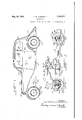
- FIG 1 is a side elevation of a motor vehicle embodying my invention
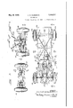
- FIG 2 is a top plan view of the chassis of the vehicle shown in Figure l, with the fenders and running board and body and the engine hood all removed;
- FIG. 3 is a longitudinal section through the chassis on the line 3--3 of Figure 2 and showing the main units of the chassis in side elevation;
- Figure 4 is a front elevation of the chassis
- Figure 5 is a rear elevation of the chassis
- Figure 6 is a view partly in top plan and partly broken away on the line 6-6 of Figure 4, and showing the front supporting members or movable axles and their relation to the front wheels and to the transmission casing;
- Figure 7 is a section through one of the movable supporting members or axles on the line l---! of Figure 6;
- Figure 8 is a section corresponding to Figure 7 but showing a modified construction
- Figure 9 is a section on the line 9-9 of Figure 6, and showing the relation of the movably supported members or axles to the transmission housing;
- Figure 10 is a partial section on the line Ill-l0 of Figure 9 and showing the compressed rubber mounting of one of the movable members or axles;
- FIG 11 is a section through this same mounting on the line IIH of Figure 10;
- Figure 12 is a vertical section through the left front wheel, looking toward the rear of the car, and showing portions of some of the associated supporting and driving parts;
- Figure 13 is a partial section on the line l3l3 of Figure 12 and showing the arrangement of the wheel spindle;
- Figure 14 is a partial section through the spindle mounting on the line l4l4 of Figure 12;
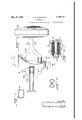
- - Figure 15 is a view showing the engine with the transmission housing attached, and with the mounting for'the opposite ends of the power or engine-transmission unit shown adjacent the opposite ends thereof, but with the parts separated and partly broken away, the better to show their relationship;
- Figure 16 is a perspective of the framework which supportsthe front end of the power or engine-transmission unit, and which in turn is supported fromthe transverse dash at the rear of the engine; 1'
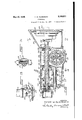
- Figure 17 is a section through the transmission on the line "-11 of Figure 6;
- Figure 18 is a top plan view of the transmission shown in Figure 17, with its associated parts, partly broken away in a vertical plane passing through the axis of the live driving'axle shafts which extend to and drive the front wheels;
- Figure 19 is a transverse vertical section through the transmission on the line l9l9 of Figure 17, and showing the reverse drive gearing;
- Figure 20 is a partial section on the line 20-20 of Figure 19 and also showing part of the reverse drive gearing;
- Figure 21 is a rear elevation of the clutch looking in the direction'of the arrows 2l--2l in Figure 17, and showing the driving portion of the engine crank shaft in transverse vertical section;
- Figure 22 is a section through the clutch on the line 22-22 of Figure 21;
- Figure 23 is a section through the base portion of the body on the line 23-23 of Figure 2;
- Figure 24 is a view on a larger scaleof one side wall, and the adjacent portion of the run-. ning board, of the base shown in Figure 23;
- Figure 25 is a section on the line 25-45 of Figure 5 and showing the rear axle construction in a plane just inside the side wall of the base of the body;
- Figure 26 is a top plan view of the parts shown in Figure 25 but with the side wall of the base shown in section;
- Figures 27, 28, 29, 30 and 32 are respectively vertical sections through alternative front wheel constructions.
- Figure 31 is a partial vertical section through the wheel spindle of Figure 30;
- the vehicle preferably includes a body or rear. section or unit which may be mounted upon or formed with a light but strong-base, shown as being of novel box-like section, and which is supported in a novel manner upon the rear road wheels, together with a front or driving section or unit which carries the engine and the mechanism through which the front wheels are driven by the engine.
- the two sections or units may be bolted or otherwise fastened together substantially in the transverse plane of the dash to form a complete chassis, or in fact (except for the engine hood or its equivalent) a complete vehicle.
- the relation of the front unit to the rear or body unit includes a number. of novel phases, such as the above-discussed mounting of the engine which permits it to swivel freely with respect to the body, and to transmit its torque directly to the front or driving wheels by a novel arrangement.
- the wheels directly support the engine, for example, through novel movable axle sections which are shown seated in compressed rubber sockets or the like in the sides of the power unit, with the engine in turn supporting through its swivel mounting a framework which carries the load of the front end of the vehicle and which is attached to the front end of the body section or rear unit.
- This particular illustrative embodiment includes a rear or body section or unit comprising a novel base I shown in detail in Figures 23 and 24.
- This base not only forms a part of the body proper l2, (Fig. l) which is mounted on the base III in the form shown in Figures 23 and 24, but may also be regarded as a substitute for the usual chassis frame which I find it unnecessary to employ as a separate element of the vehicle.
- the base ID as shown in Figures 2 and 23 comprises upper and lower sheet metal stampings I I and I3 welded or otherwise permanently secured to longitudinally extending side channel members It and straight members l jointly forming boxsection side rails or supports.
- the upper and lower edges of the side members l4 and I5 are also preferably welded together by seam-welding or by a series of spot welds or the like.
- the base to twisting In order to increase the resistance of the base to twisting, it may be made more rigid by providing it with a series of corrugations or reinforcing grooves l6 formed in the upper and lower members H and I3 and radiating from positions adjacent a central circular corrugation or groove I1.
- the six corrugations [6 which radiate toward the two ends of the body are preferably of the same length so that they may be formed successively with a single die if desired.
- the corrugations iii in theupper member II will be filled in substantially flush by placing therein small strips of wood generally like building lath, so that the surface so formed may be covered by a carpet or mat and form the floor of the car body.
- the running boards may be formed by providing the bottom member l3 with extensions [9 on opposite sides as shown in Figure 23 and to which are secured, by welding or otherwise, longitudinally corrugated stampings 20 which may if desired house the board or metal reinforcement 2
- the running board proper 20 is preferably formed with a flange 22 seated against and welded or otherwise secured to the side member I 5.
- a dash 24 extending entirely across the vehicle and which may be formed with, or on which there may be mounted in any desired manner, as by the integral brackets 25, an instrument board 26.
- the dash and the brackets 25 may also if desired support a gasoline tank 21 having a gravity connection to the engine carburetor and provided with a filler cap 28 accessible by raising the cowl ventilator 29 just back of the removable engine hood 30.
- the dash 24 may be formed with a recess 3! adapted to be spanned by a steel stamping 32 seated and suitably secured therein and carrying a bearing 33, preferably of rubber, which forms a swivel mounting or pivot for a cylindrical boss 34 formed on the rear end of the power or engine-transmission unit, preferably in linewith the axis of rotation of the engine crankshaft.
- Theabove-mentioned power or engine-transmission unit preferably includes an engine 35, ohthe crank case of which the boss 34 is formed, and a separately formed transmission-clutch housing 36 rigidly bolted or otherwise secured to the engine 35, and which is formed at its front end with a cylindrical boss or pivot 31 also inv line with the crank shaft axis and therefore coaxial with respect to the boss 34.
- the boss 31 is swiveled or pivoted in a bearing 38 preferably of rubber, seated in a cylindrical extension 39 of an engine bracket or pyramidal supporting frame having four diverging arms 43 bolted rigidly to the four corners of the dash 24.
- the bracket or frame 33-40 may be provided with lugs 4
- the radiator 42 may be housed within a suitable shell 44 also supported from the lugs 4
- the dash 24 is shown in position on the base iii in Figure 15, and separate from the engine bracket or support 39-40. It will be understood that in the actual assembly of the parts the dash 24 with the parts which it carries, including the stamping 32 carrying the bearing 33, form a part of the front or engine unit and are rigidly bolted to the base or arms of the pyramidal supporting bracket 40 to form a separately-assembled unit with the engine-transmission or power unit and the front wheels and their associated parts.
- This unit is intended to be seated on the front end of the base H), with the dash 24 bolted or otherwise rigidly secured thereto in the position shown in Figure 15, in order to fasten the front and rear units together to complete the final assembly of the vehicle. It is of course possible to separate the engine bracket or support 40 from the dash 24 without removing the latter from the base 10, as shown in Figure 15, but it is not intended that the parts shall be assembled or disassembled in this manner, but that the front or engine unit wih its wheels and their driving mechanism shall instead form a self-contained unit which has merely to be bolted to or unbolted from the rear unit to assemble or disassemble the car.
- the front cantilever system includes the lower members 40', which are in compression, and the upper members 40, which are'in tension.
- the rear cantilever system is built into the base ill, the lower portion of which is in compression and the upper portion in tension. The tension portionsof both systems are sufficiently rigid, however, to resist compressive thrusts due to shocks and the like, which might tend to shift the dash 24. The whole, however, gives an unusually strong chassis with a greatly reduced weight.
- the inner end of the axle member 41, and the inner ends of the two arms of the member 48, are preferably H-shaped in cross-section as shown in Figure 11, and seated between compressed blocks of rubber or the like 49, the end of each axle member and the corresponding rubber block assembly being seated in a socket formed in the transmission housing 36 and completed by a cap 50 pulled up tight to compress the rubber blocks by bolts or the like
- the very long lever arm formed by the axle members 41 and 48 decreases the amplitude of movement at the inner ends of these arms, which are thus yieldably connected to the transmission case 36, to such an extent that the very small movement which is permitted by the highly compressed rubber blocks is sufficient.
- the seats for the blocks are H-shaped in section lengthwise of the axles as shown in Figure 10, as well as crosswise as shown in Figure 11, and if desired suitable bufiers or rubber blocks 52 may also be seated between the ends of the axles and the ends of the sockets in housing 36 to prevent any possibility of a rigid metal-to-metal contact, in the case of a wheel striking a curb .or other obstruction.
- the forking of the member 48 to provide two independently mounted arms gives a three point suspension for each wheel, and that each of the three arms forming that suspension has a yielding resilient movement independently of the other two arms, and that the movement of each wheel is entirely independent of the movement of the other wheels.
- the wheels have what may be regarded as parallelogram-linkage mountings, combined with center-point steering, it will also be noted that even in case of a blow-out of the tire there is substantially no tendency to react on the steering gear and cause the car to swerve. This is because the swiveling axis of the wheel remains the reaction of the driving impulses on the pow-- er unit are yieldingly transmitted through the axle members 47! and 48 directly to the wheels 46, which themselves provide additional cushioning ofthese vibrations, since these axle members and the wheels form the sole means pre- -axis of its supports 34 and 31?.
- the above-described yieldingly-mounted supporting arms or axle sections 41 and 48 are formed at their outer ends with horizontal eyes embracing pivot pins 53 connecting them to pairs of spaced lugs or forks 54 formed at the top and bottom of a novel support 55 bowed rearwardly to carry a vertical king pin 56, which swivels to the support 55 a knuckle 51.
- the latter may be formed with a tubular central portion in which are seated inner and outer ball bearings 58 and 59 in which is journalled a driving spindle 69.
- the driving spindle 69 has an enlarged inner end forming the driven portion of a universal joint, and which is seated against the inner ball bearing 58, and is held in place by a collar 6! threaded, or pinned or otherwise fixed thereon and engaging the outer ball bearing 59.
- the outer end of the driving spindle 60' is preferably conical, and has splined or keyed thereon a correspondingly-shaped socket in a spider or wheel member 62 held by an axle nut 63.
- the wheel member is preferably formed integrally with a brake drum within which are arranged the shoes 64 of a hydraulic brake, shown actuated by a wheel cylinder assembly 65 with which there communicates the usual hydraulic line 69.
- the shoes 64 may be mounted on stationary anchors or pivots 61 carried by a backing plate or other stationary support 68 bolted or otherwise secured to the knuckle 51.
- the tire 69 of the wheel may be mounted in a demountable rim 15 shown as being of the drop-center type, and which may have welded or otherwise secured thereto a flange "ll adapted to be detachably bolted to a cooperating flange 72 formed on the wheel and drum member 62.
- the member 62 has its outer face in the form of three or four angularly-spaced spokes so that complete access is afforded to the brake mechanism inside of the drum.
- the entire Wheel and brake assembly may be closed in by a cover plate or fairing l3 engaging and suitably clipped or otherwise secured to the rim I0, thus providing,,with the tire 69 and the fender 22, a structure which is almost completely streamlined. If preferred the cover or fairing 19 may be held by a screw 14 threaded into the end of the spindle 60.
- the axis of the king pin 56 is substantially in the central plane of the wheel, as appears from Figure 12, thus giving "center-point steering.
- the effective length of the arm or axle 41 is slightly shorter than that of the arm or axle 48, so that the wheel does not move with its plane constantly vertical as would be the case if the arms 41 and 48 gave a parallelogram movement. Instead the movement of the'upper part of the wheel is accentuated, it being given an additional arc of movement about the center of the lower pin 53, which additional movement is compounded with the normal upward and downward movement of the wheel to compensate for the movement which would otherwise take place at the bottom of the tire in a direction toward and from the vehicle and which might give an undue tendency to wear the tire against the road surface.
- This compound movement maintains the position of the center point 15, which is the point momentarily at the bottom of the tire and in contact with the road, exactly in a straight vertical line instead of an arc.
- the slight additional movement of the top of the wheel toward and fromthe vehicle is not objectionable, and
- this arrangement eliminates transverse movewheels with respect to the vehicle body.
- the inner end of the drive spindle Ell which is keyed to and which drives and supports the wheel, is formed with a plurality of fingers having cam slots 18 formed therein, which cooperate with cor responding cam slots I'I in driving fingers formed on the end of a live or driving axle shaft 18 to receive driving balls 18 to form a universal joint of the Weiss type.
- this type of joint relative axial movements of separation and approach of the axle shafts 60 and I8 is permitted by movements of the driving balls I8 in the cooperating cam slots 18 and 11, without changing the effectiveness of the drive between the two axle sections.
- one of the features of my invention relates to the use in the described combination of a joint of this type which may be placed a ve y substantial distance from the axis of the king pin 58 without interfering with the swiveling movements of the wheel in steering, and without giving any unevenness in the driving torque acting on the wheel.
- 8, and the connecting joint, are shown housed in a tubular jointed housing including parts 80 and 8
- is also formed with a spherical portion (provided if desired with a felt packing or the like 82), movably fitting over a corresponding spherical housing 88 shown ashaving joined thereto a flanged base 88 urged axially outward by a. compressed coil spring 88 confined between the base 84 and the adjacent face of the transmission housing 88 ( Figure 18).
- a. compressed coil spring 88 confined between the base 84 and the adjacent face of the transmission housing 88 ( Figure 18).
- Within the movable housin joint thus formed is arranged another universal joint of the "Weiss type having driving balls 88, and drivably connecting to the live axle or driving shaft I8 a short drive shaft or axle section 81 rotatably mounted in a ball bearing 88' carried by the transmission housing 88.
- is keyed to a differential pinion 88 journalled in a tubular boss 80 forming part of a differential pinion carrier 8
- bosses 88 on opposite sides of the differential being joumalled in tapering roller bearings 82 mounted in seats formed in the transmission housing 88, and adjustably held by an externally threaded nut 88 adapted to be locked in adjusted position by a key or the like 88. While this arrangement is only shown on one side of Figure 18, it will be appreciated that the same construction is to be found on the left side driving the axle 18 on that side.
- the differential pinions 88 mesh in the usual way with driving or side pinions 88 ( Figures 1'7 and 18), which are freely rotatable on a transverse supporting shaft 88 carrled by the differential pinion carrier 8
- the carrier in turn has bolted or otherwise secured thereto a worm gear 81, or the equivalent, meshing with adriving worm 88 shown integrally formed on a hollow shaft 88 extending longitudinally of the transmission housing 38, and substantially in line with the engine crank-shaft, and supported by tapered roller bearings I00 carried by the housing 36 just in front of and just behind the differential.
- the bottom of the casing 36 may be provided with an opening having a detachable cover IOI which can be removed to facilitate adjustment of the differential.
- the change-speed transmission selected for illustration is of the progressive sliding-gear type, and as best appears in Figure 17 is arranged in front of the above-described differential. While a change-speed gear or transmission of other types can be used if desired, I now prefer the construction shown, in which the drive is from a driven shaft I02 extending forwardly from the clutch described below and which connects it to the engine crank shaft, and which is supported for the greater part of its length in the abovementioned tubular shaft 99, and which has its extreme forward end supported in a ball hearing or the like I03 arranged in the front end of the housing 36.
- the front end of this shaft is provided with a one-way clutch member I04 accessible through the open end of the boss 31, for inter-engagement with a hand crank for use in case of a failure of the electric starting mechanism.
- the front end of the shaft I02 just beyond the end of the shaft 88 also has mounted thereon and keyed thereto a, driving pinion I05 meshing with a larger pinion I06, which larger pinion forms part of a gear cluster I0'I rotatably mounted on a countershaft I08 carried by the housing 38.
- cluster I0! is also formed with a low speed gear I08 and with a reverse gear I I0 driving a reverse idler gear III.
- a shiftable sliding driven gear II2 operated by a shifter fork H4, on a lengthwise-movable shifter rod I I8 actuated in any suitable manner from the dash.
- the rear face of the pinion I05 and the front face of the sliding gear II2 are formed in the usual manner with inter-engaging clutch faces in the form of short splines or teeth formed externally on the pinion I05 and' internally on the gear II2.
- the flywheel is provided with a ball
Landscapes
- Engineering & Computer Science (AREA)
- Chemical & Material Sciences (AREA)
- Combustion & Propulsion (AREA)
- Transportation (AREA)
- Mechanical Engineering (AREA)
- Body Structure For Vehicles (AREA)
Description
y 0 1939- v. w. KLIESRATH 2,160,271
AUTOMOBILE Original Filed Jan 14, 1933 14 Sheets-Sheet 2 i "-l llllli IN VENTOR. I
V/CTOR W/{L/ESRHTH ATTORNEYS May 30, 1939. v. w. KLIESRATH AUTOMOB ILE Original Filed Jan. 14, 1933 14 Sheets-Sheet 3 1 I nnliliEulinli INVENTbR. V/CTOR W. KL/ESRHTH May 36, 1939. v. w. KLIESRATH AUTOMOBILE 14 Sheets- Sheet 4 Original Filed Jan. 14, 1933 INVENTOR V/CTOR W. KL IESRATH ark/ 1 60M). M m AtTQ NEYS.
y l939- V. w. KLI ESRATH 2,160,271
I AUTOMOBILE Original Filed Jan. 14, 1953 14 Sheets-Sheet5 VICTOR w KL/ESEHTH BY ym (E 4,, D W M ATTORNEYS:
y 1939- I v. w. KLIESRATH 2,160,271
AUTOMOBILE Y Origirial Filed Jan. 14, 1953 14 Sheets-Sheet 6 INVENT OR. ig/670R m hL/ESRHTH ATTORNEYS.
. May 30, 1939. v. w. KLIESRATH AUTOMOBILE Original Filed Jan. 14, 1933 14 Sheets-Sheet '7 Ch y R IN VENTOR.
V/CTOR 1/1 KL/ESRHTH ATTORNEYS ay 30, 1939. v. w. KLIESRATH AUTOMOB ILE Original Filed Jan. 14, 1933 14 Sheets-Sheet 8- INVENTOR. V/CTOR KL/ESR/QTH ATTORNEYS y' 1939- v. w. KLIESRATH 2,160,271
Q AUTOMOBILE Original Filed Jan. 14, 1933 14 Sheets-Sheet 9 Fig]. '22
INVENT OR.
g/c TOR w m/asRx-vm ATTORNEYS May 30, 1939. v. w. KLI ESRATH 2,160,271
' AUTOMOBILE Original Filed Jan. 14, 1953 14 Sheets-Sheet 1O INVENTOR.
E1 Z 53 \B/YICTOR WKL/ESRATH ATTORNEYS May 30, 1939. v. w. KLIESRATH 2,160,271
AUTOMOBILE Original Filed Jan. 14, 1933 14 Sheets-Sheet ll INVENTOR.
L V/CTOR w KL/ESRHTH BY ATTORNEYS.
May 30, 1939. -v. VV..KLIESRATH AUTOMOBILE Original Filed Jan. 14, 1933 14 Sheets-Sheet l2 INVENIOR. v/croF? w. KL/EJSRHTH BY WW BDQMM ATTORNE V. W. KLIESRATH AUTOMOBILE May 30, 1939.
Original Filed Jan. 141, @933 14 Sheets-Sheet 13 9M mo INVENTOR. 5/0 TOR w hL/ESRF) TH ATTORNEYS.
- Mfiy 30, 1939. v. w. KLIESRATH 2,160,271
AUTOMOBILE Original Filed Jan. 14, 1933 14 Sheets-Sheet l4 "Fig. 5E)
INVENTOR.
'l {CTOR W.-KLIESR/-)TH W XTTERNEYs.
Patented 'May 30, 1939 UNITED STATES PATENT OFFICE 2,160,271 AUTOMOBILE tion of Illinois Original application January 14, 1933, Serial No. 651,821. Divided and this application January 22, 1938, Serial No. 186,290
50' Claims.
This invention relates to automobiles and other motor vehicles, and is illustrated as embodied in an automobile having a novel arrangement of parts giving a very light weight and consequent high acceleration, and which is of simple and inexpensive construction and which is preferably of the front-wheel drive variety.
One feature of the invention relates to the construction of the vehicle in two sections, shown as being respectively afront section carrying the power plant and a rear section shown as being a sort of trailer unit which carries the body and which is attached in a novel manner to the front section. Since practically all the operating parts of the vehicle are on the front section, this permits a very simple and inexpensive method of assembling the complete car, with the operating parts fully assembled on the front unit which when complete is bolted or otherwise secured to the rear unit. I also prefer to take advantage of this construction to form the rear unit as practically a vehicle body on which the rear road wheels are mounted; that is, I eliminate the usual frame by mounting the rear wheels directly on the body and attaching the body to the abovedescribed front unit wich carries the operating mechanism.
According to a very important feature of the invention, advantage is taken of the foregoing construction to provide in the front unit a frame or other engine support projecting forwardly from the vehicle dash, which forms the rear. transverse element of the front unit and which is directly secured to the rear unit of the vehicle, and to pivotally support the power plant or engine-transmission unit therein.
This greatly facilitates an arrangement which I believe to be'entirely new, in this or any other type of motor vehicle, in which the pivotally mounted power unit is provided with axle sections or the like which directly carry the road wheels. By this novel arrangement it will be seen that the reaction torque of the engineis not transmitted to the, body but is transmitted directly to the road wheels through the axle sections which engage the pivotally mounted power unit. This secures a highly desirable result, which has been approximated by'various yielding mountings ofthe power units in thechassis frame but which has never before been completely achieved, in entirely eliminating the engine re action impulses from any possibility'of being transmitted to the vehiclebody.
With the described arrangement, therefore, so
far as passengers in the vehicle body are con cerned, even an engine with a relatively small number xii-cylinders does not produce any reactionary vibrations andgives the effect of being as smooth as an electric motor or the like. At the same time the vehicle body is provided with what in effect is a three-point suspension, since it is supported on the pivotal mounting of the power unit at its front end and on the rear road wheels at its rear end. The described arrangement therefore has the additional advantage of entirely eliminating any twisting or weaving of the vehicle body.
In reducing to a practical embodiment the above described broad conception, I have provided numerous novel subcombinations which contribute very materiallyto the success of the broad combination, and which also in themselves embody substantial novelty. Among the more important of these is a novel spring suspension giving individual springing of each of the four wheels, by the use of rigid axle sections which are yieldingly mounted at their inner ends in rubber blocks or equivalent yielding mountings. The yielding mountings are preferably arranged, as explained above, in sockets formed in the pivotally mounted power unit for the front wheels, and are shown mounted on the vehicle body for the rear wheels. Preferably the set of axle sections for each wheel includes at least one section which is Y-shaped in horizontal plan, so that it resists fore-and-aft movement of its wheel,
and I prefer to form the axle sections by welding,
or. otherwise securing together face to face, channel-section steel stampings, thus giving a very strong hollow box-section.
While many of the advantages mentioned above could be secured with the usual rear-wheel drive, the advantages are greatly augmented by combining therewith in a novel manner a frontwheel drive, shown as including driving-axle shafts arranged between the above-described upper and lower axle sections and provided at their outer ends with universal joints and associated parts arranged in a novel manner and through which the wheels are driven. The driving shafts may advantageously be housed in an improved form of tubular sectional housing, and
at their inner ends are universally jointed to shaft sections driven by a differential which is mounted in the power unit, preferably between the engine and a novel transmission which is shown as being of the progressive sliding-gear type.
The power unit-embodies substantial novelty in the arrangement and construction of the transmission and differential and in the construction and arrangement of the clutch, particularly in the arrangement of a clutch of the novel form hereinafter described between the front end of the engine crank shaft and the differential, and arranged to drive a forwardly-extending shaft which forms the driving shaft of the transmission and on which there is sleeved a hollow shaft provided with a worm or other gear for driving the differential. The transmission is thus arranged at the extreme forward end of the car and serves to connect at different speeds the front ends of the forwardly-extending clutch shaft and the differential-driving hollow shaft.
The above-mentioned dash or transverse supporting element of the front vehicle unit in itself embodies some features of novelty, particularly in being provided with a stamped or other resilient support for a bearing which pivotally carries the rear end of the power unit. As explained above, a novel form of pyramidal frame serving as an engine support is secured at its rear end or base to the transverse dash, and projects forwardly therefrom to carry the front engine support. The dash may also, if desired, carry the fuel tank which may be provided with a filler opening accessible through a cowl ventilator ;.rovided adjacent the engine hood.
The mounting for the rear wheels, while embodying many of the features of the front wheel mountings, has also some additional features of novelty in the mounting of the sockets for the axle sections on clamps or the like engaging a pair of transversely extending reinforcing elements, preferably of tubular construction, which span the rear portion of the base or lower part of the body. The wheel assemblies, both front and rear have also some features of novelty in the use of demountable outer plates or fairings which cooperate with the tires and the fenders to give a completely stream-lined effect for the entire lower portion of the vehicle, in a novel arrangement of spindle parts and associated bearings and the like which facilitate the use of the above-described arrangement of axle sections giving an individual springing of each axle, and in the wheel and brake drum and brake structure and arrangement and the like.
Another important advantage which is secured by the use of the above-discussed arrangement is that the usual chassis frame may be eliminated and in place thereof the body itself may be formed with a novel box-section reinforced base which is light but exceedingly strong and which has a flat bottom paralleling the ground at the level of the bottom of the rear axle in the ordinary car, so that the entire body is lowered very substantially and at the same time all projecting parts below the car are eliminated entirely and the bottom part of the car is in effect completely stream-lined. The use of a construction of this sort permits the use of an improved construction for mounting of the running boards and fenders and the like.
The entire design discussed above, when used as a coherent whole in one vehicle, gives a very light weight with consequent high acceleration and high road speeds, this effect being accentuated by the facility with which the assembly can be effectually stream-lined andby the elimination of most of the usual projecting parts which add to the wind-resistance of the ordinary car; In connection with the very simplespringing ofthe wheels by the use of the rigid parallel axle sections with their rubber seats,'1 prefer to use very small diameter wheels with very large tires of the type known as super-balloon tires, which not only add to the resilient effect of the spring suspension but which also flatten out substantially against the road and increase the tractive effect of the wheels. This adds to the degree of acceleration possible and to the effectiveness of the brakes in decelerating the car, and so far as these features of operation are concerned the flattening of the tires in this manner against the road may be regarded as providing an equivalent for the tractive effect produced by the weight of the usual heavier cars.
The above and other objects and features of the invention, including an improved steering gear arrangement and a novel arrangement of the hydraulic lines of a system of hydraulic fourwheel brakes, and other arrangements of parts and desirable particular constructions, will be apparent from the following description of the illustrative embodiment shown in the accompanying drawings, in which;
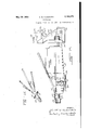
Figure 1 is a side elevation of a motor vehicle embodying my invention;
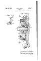
Figure 2 is a top plan view of the chassis of the vehicle shown in Figure l, with the fenders and running board and body and the engine hood all removed;
Figure 3 is a longitudinal section through the chassis on the line 3--3 of Figure 2 and showing the main units of the chassis in side elevation;
Figure 4 is a front elevation of the chassis;
Figure 5 is a rear elevation of the chassis;
Figure 6 is a view partly in top plan and partly broken away on the line 6-6 of Figure 4, and showing the front supporting members or movable axles and their relation to the front wheels and to the transmission casing;
Figure 7 is a section through one of the movable supporting members or axles on the line l---! of Figure 6;
Figure 8 is a section corresponding to Figure 7 but showing a modified construction;
Figure 9 is a section on the line 9-9 of Figure 6, and showing the relation of the movably supported members or axles to the transmission housing;
Figure 10 is a partial section on the line Ill-l0 of Figure 9 and showing the compressed rubber mounting of one of the movable members or axles;
Figure 11 is a section through this same mounting on the line IIH of Figure 10;
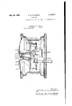
Figure 12 is a vertical section through the left front wheel, looking toward the rear of the car, and showing portions of some of the associated supporting and driving parts;
Figure 13 is a partial section on the line l3l3 of Figure 12 and showing the arrangement of the wheel spindle;
Figure 14 is a partial section through the spindle mounting on the line l4l4 of Figure 12;
-Figure 15 is a view showing the engine with the transmission housing attached, and with the mounting for'the opposite ends of the power or engine-transmission unit shown adjacent the opposite ends thereof, but with the parts separated and partly broken away, the better to show their relationship;
Figure 16 is a perspective of the framework which supportsthe front end of the power or engine-transmission unit, and which in turn is supported fromthe transverse dash at the rear of the engine; 1'
Figure 17 is a section through the transmission on the line "-11 of Figure 6;
Figure 18 is a top plan view of the transmission shown in Figure 17, with its associated parts, partly broken away in a vertical plane passing through the axis of the live driving'axle shafts which extend to and drive the front wheels;
Figure 19 is a transverse vertical section through the transmission on the line l9l9 of Figure 17, and showing the reverse drive gearing;
Figure 20 is a partial section on the line 20-20 of Figure 19 and also showing part of the reverse drive gearing;
Figure 21 is a rear elevation of the clutch looking in the direction'of the arrows 2l--2l in Figure 17, and showing the driving portion of the engine crank shaft in transverse vertical section;
Figure 22 is a section through the clutch on the line 22-22 of Figure 21;
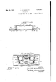
Figure 23 is a section through the base portion of the body on the line 23-23 of Figure 2;
Figure 24 is a view on a larger scaleof one side wall, and the adjacent portion of the run-. ning board, of the base shown in Figure 23;
Figure 25 is a section on the line 25-45 of Figure 5 and showing the rear axle construction in a plane just inside the side wall of the base of the body;
Figure 26 is a top plan view of the parts shown in Figure 25 but with the side wall of the base shown in section;
Figures 27, 28, 29, 30 and 32 are respectively vertical sections through alternative front wheel constructions; and
Figure 31 is a partial vertical section through the wheel spindle of Figure 30;
As explained above, the vehicle preferably includes a body or rear. section or unit which may be mounted upon or formed with a light but strong-base, shown as being of novel box-like section, and which is supported in a novel manner upon the rear road wheels, together with a front or driving section or unit which carries the engine and the mechanism through which the front wheels are driven by the engine. The two sections or units may be bolted or otherwise fastened together substantially in the transverse plane of the dash to form a complete chassis, or in fact (except for the engine hood or its equivalent) a complete vehicle. -The relation of the front unit to the rear or body unit includes a number. of novel phases, such as the above-discussed mounting of the engine which permits it to swivel freely with respect to the body, and to transmit its torque directly to the front or driving wheels by a novel arrangement.
The wheels directly support the engine, for example, through novel movable axle sections which are shown seated in compressed rubber sockets or the like in the sides of the power unit, with the engine in turn supporting through its swivel mounting a framework which carries the load of the front end of the vehicle and which is attached to the front end of the body section or rear unit. It will be appreciated that many of the advantages of the invention can be secured without using all of the diflerent novel structures described below, but the full avantages of the construction with its light weight and concurrent quick acceleration, its low body height without sacrifice of head room and without diminishing the usual road clearance, and the other advantages discussed above and pointed out below, can best be secured in a vehicle such as shown in the drawings and now to be particularly described as comprising the preferred embodiment, and which includes all of the various features of novelty in their intended combination and co-relation.
This particular illustrative embodiment includes a rear or body section or unit comprising a novel base I shown in detail in Figures 23 and 24. This base not only forms a part of the body proper l2, (Fig. l) which is mounted on the base III in the form shown in Figures 23 and 24, but may also be regarded as a substitute for the usual chassis frame which I find it unnecessary to employ as a separate element of the vehicle.
The base ID as shown in Figures 2 and 23 comprises upper and lower sheet metal stampings I I and I3 welded or otherwise permanently secured to longitudinally extending side channel members It and straight members l jointly forming boxsection side rails or supports. The upper and lower edges of the side members l4 and I5 are also preferably welded together by seam-welding or by a series of spot welds or the like.
In order to increase the resistance of the base to twisting, it may be made more rigid by providing it with a series of corrugations or reinforcing grooves l6 formed in the upper and lower members H and I3 and radiating from positions adjacent a central circular corrugation or groove I1. The six corrugations [6 which radiate toward the two ends of the body are preferably of the same length so that they may be formed successively with a single die if desired. In the arrangement of Figure 23 it is intended that the corrugations iii in theupper member II will be filled in substantially flush by placing therein small strips of wood generally like building lath, so that the surface so formed may be covered by a carpet or mat and form the floor of the car body.
The running boards may be formed by providing the bottom member l3 with extensions [9 on opposite sides as shown in Figure 23 and to which are secured, by welding or otherwise, longitudinally corrugated stampings 20 which may if desired house the board or metal reinforcement 2|.
The running board proper 20 is preferably formed with a flange 22 seated against and welded or otherwise secured to the side member I 5.
On the front end of the base member If], there is shown arranged a dash 24 extending entirely across the vehicle and which may be formed with, or on which there may be mounted in any desired manner, as by the integral brackets 25, an instrument board 26. The dash and the brackets 25 may also if desired support a gasoline tank 21 having a gravity connection to the engine carburetor and provided with a filler cap 28 accessible by raising the cowl ventilator 29 just back of the removable engine hood 30.
The dash 24 may be formed with a recess 3! adapted to be spanned by a steel stamping 32 seated and suitably secured therein and carrying a bearing 33, preferably of rubber, which forms a swivel mounting or pivot for a cylindrical boss 34 formed on the rear end of the power or engine-transmission unit, preferably in linewith the axis of rotation of the engine crankshaft.
Theabove-mentioned power or engine-transmission unit preferably includes an engine 35, ohthe crank case of which the boss 34 is formed, and a separately formed transmission-clutch housing 36 rigidly bolted or otherwise secured to the engine 35, and which is formed at its front end with a cylindrical boss or pivot 31 also inv line with the crank shaft axis and therefore coaxial with respect to the boss 34.
As best appears in Figures 2, 3, and 15, the boss 31 is swiveled or pivoted in a bearing 38 preferably of rubber, seated in a cylindrical extension 39 of an engine bracket or pyramidal supporting frame having four diverging arms 43 bolted rigidly to the four corners of the dash 24. The bracket or frame 33-40 may be provided with lugs 4| or other suitable supporting means for the radiator 42, which may be connected as shown in Figure 3 at its upper end to the dash 24 by suitable struts or tie rods 43. The radiator 42 may be housed within a suitable shell 44 also supported from the lugs 4| and giving a streamlined appearance as shown in Figure 1.
In order to facilitate the illustration of the positions of the parts, the dash 24 is shown in position on the base iii in Figure 15, and separate from the engine bracket or support 39-40. It will be understood that in the actual assembly of the parts the dash 24 with the parts which it carries, including the stamping 32 carrying the bearing 33, form a part of the front or engine unit and are rigidly bolted to the base or arms of the pyramidal supporting bracket 40 to form a separately-assembled unit with the engine-transmission or power unit and the front wheels and their associated parts.
This unit is intended to be seated on the front end of the base H), with the dash 24 bolted or otherwise rigidly secured thereto in the position shown in Figure 15, in order to fasten the front and rear units together to complete the final assembly of the vehicle. It is of course possible to separate the engine bracket or support 40 from the dash 24 without removing the latter from the base 10, as shown in Figure 15, but it is not intended that the parts shall be assembled or disassembled in this manner, but that the front or engine unit wih its wheels and their driving mechanism shall instead form a self-contained unit which has merely to be bolted to or unbolted from the rear unit to assemble or disassemble the car.
By the above arrangement an exceptionally strong but light chassis is secured. All the chassis strains center themselves finally in the very strong and rigid transverse reinforced dash 24 or its equivalent, which may be regarded as a transverse bridge or key member from which the Weight is transmitted to the wheels by what are in effect novel front and rear cantilever systems. The front cantilever system includes the lower members 40', which are in compression, and the upper members 40, which are'in tension. The rear cantilever system is built into the base ill, the lower portion of which is in compression and the upper portion in tension. The tension portionsof both systems are sufficiently rigid, however, to resist compressive thrusts due to shocks and the like, which might tend to shift the dash 24. The whole, however, gives an unusually strong chassis with a greatly reduced weight.
It will be seen that with the engine and its associated transmission mechanism mounted as described above, the engine swivels freely with respect to the body of the car and with respect to the base l0, which can be regarded as a substitute for the usual chassis frame, and therefore cannot possibly transmit to the body any vibrations due to the reaction from the torque of 'the engine pistons acting periodically on the engine crank shaft in driving the vehicle. It will be appreciated that the impulses of the successively effective pistons on the engine crank shaft are balanced by corresponding reactions on the engine cylinder and crank case assembly. Normal- 1y these reactions are transmitted directly to the vehicle frame, and while constructions have recently been adopted in automotive construction for cushioning these reactions against the chassis frame, their efiect is thereby only minimized and not eliminated. I propose to eliminate the effects of these vibrations entirely, so far as their effect on the vehicle body, and therefore on the passengers, is concerned, by transmitting them directly to the front wheels without any reaction whatever on the vehicle body, or on the base Iii, which corresponds to the usual chassis frame.
The above described mounting of the power unit, which permits it to swivel freely about the axis of the crankshaft on the parts 34 and 31 which are seated respectively in the bearings 33 and 38, is an important feature in securing the desired elimination of the torque reactions. Another important feature in securing this desired result, and at the same time securing very important advantages in providing independent springing of the two front wheels, and preferably in a manner facilitating the driving of the front wheels, consists in the supporting of the front end of the vehicle, through the bearing 38 and the boss 31, upon the transmission housing 36 or other part of the power unit, on opposite sides of which are mounted novel axle members carrying the front road wheels 46.
These wheels and their mounts in themselves embody features of novelty which are discussed below in describing Figure 12, but in connection with the engine mounting the interesting feature is the mounting of the wheels on upper and lower supporting or axle members 47 and 48, one of which members (shown as the lower member 48) is Y-shaped in plan view as appears in Figure 6, with its stem carrying the lower end of the wheel spindle and with the two arms engaging the bottom of the transmission housing 36. The inner end of the axle member 41, and the inner ends of the two arms of the member 48, are preferably H-shaped in cross-section as shown in Figure 11, and seated between compressed blocks of rubber or the like 49, the end of each axle member and the corresponding rubber block assembly being seated in a socket formed in the transmission housing 36 and completed by a cap 50 pulled up tight to compress the rubber blocks by bolts or the like It will be appreciated that the very long lever arm formed by the axle members 41 and 48 decreases the amplitude of movement at the inner ends of these arms, which are thus yieldably connected to the transmission case 36, to such an extent that the very small movement which is permitted by the highly compressed rubber blocks is sufficient. to allow an amplitude of movement to the outer ends of the axles which, taken with the use of very large section low-pressure tires' I prefer to form the axle members 41 and 48 by welding together, face to face, stamped steel parts of single channel section as shown in Figure 7, or double channel section as shown in Figure 8. This facilitates the formation of the seats for the rubber blocks 49 shown in Figures 10 and 11. It will be noted by comparison of Figures 10 and 11 that the blocks 49 not only cushion the axles against upward and downward movement at their outer ends, which produces a twisting of the innerends in the rubber seats,
but also cushions them against lengthwise movement which is also resisted by resilient distortion of the blocks 49. To this end the seats for the blocks are H-shaped in section lengthwise of the axles as shown in Figure 10, as well as crosswise as shown in Figure 11, and if desired suitable bufiers or rubber blocks 52 may also be seated between the ends of the axles and the ends of the sockets in housing 36 to prevent any possibility of a rigid metal-to-metal contact, in the case of a wheel striking a curb .or other obstruction.
It will be noted that the forking of the member 48 to provide two independently mounted arms gives a three point suspension for each wheel, and that each of the three arms forming that suspension has a yielding resilient movement independently of the other two arms, and that the movement of each wheel is entirely independent of the movement of the other wheels.
Since the wheels have what may be regarded as parallelogram-linkage mountings, combined with center-point steering, it will also be noted that even in case of a blow-out of the tire there is substantially no tendency to react on the steering gear and cause the car to swerve. This is because the swiveling axis of the wheel remains the reaction of the driving impulses on the pow-- er unit are yieldingly transmitted through the axle members 47! and 48 directly to the wheels 46, which themselves provide additional cushioning ofthese vibrations, since these axle members and the wheels form the sole means pre- -axis of its supports 34 and 31?.
venting the turning of the power unit about the I regard this combination, which at the same time cushions these vibrations and-transmits them directly to the wheels without any reaction on the vehicle body, by means which at the same time serves as an engine support and as an individual spring suspension for the wheels, and which also provides a self-contained engine-front-drive unit adapted to be assembled as such and then bolted or otherwise attached as an entirety to a rear unit, as forming a substantial contribution which is entirely new as a combination as well as in many of its parts and sub-combinations.
The above-described yieldingly-mounted supporting arms or axle sections 41 and 48 are formed at their outer ends with horizontal eyes embracing pivot pins 53 connecting them to pairs of spaced lugs or forks 54 formed at the top and bottom of a novel support 55 bowed rearwardly to carry a vertical king pin 56, which swivels to the support 55 a knuckle 51. The latter may be formed with a tubular central portion in which are seated inner and outer ball bearings 58 and 59 in which is journalled a driving spindle 69. i
The driving spindle 69 has an enlarged inner end forming the driven portion of a universal joint, and which is seated against the inner ball bearing 58, and is held in place by a collar 6! threaded, or pinned or otherwise fixed thereon and engaging the outer ball bearing 59. The outer end of the driving spindle 60' is preferably conical, and has splined or keyed thereon a correspondingly-shaped socket in a spider or wheel member 62 held by an axle nut 63. The wheel member is preferably formed integrally with a brake drum within which are arranged the shoes 64 of a hydraulic brake, shown actuated by a wheel cylinder assembly 65 with which there communicates the usual hydraulic line 69. The shoes 64 may be mounted on stationary anchors or pivots 61 carried by a backing plate or other stationary support 68 bolted or otherwise secured to the knuckle 51.
The tire 69 of the wheel, shown as a large- 52 I section low-pressure super-balloon tire, may be mounted in a demountable rim 15 shown as being of the drop-center type, and which may have welded or otherwise secured thereto a flange "ll adapted to be detachably bolted to a cooperating flange 72 formed on the wheel and drum member 62. Preferably the member 62 has its outer face in the form of three or four angularly-spaced spokes so that complete access is afforded to the brake mechanism inside of the drum. The entire Wheel and brake assembly may be closed in by a cover plate or fairing l3 engaging and suitably clipped or otherwise secured to the rim I0, thus providing,,with the tire 69 and the fender 22, a structure which is almost completely streamlined. If preferred the cover or fairing 19 may be held by a screw 14 threaded into the end of the spindle 60.
It should be noted that the axis of the king pin 56 is substantially in the central plane of the wheel, as appears from Figure 12, thus giving "center-point steering. It should also be noted that the effective length of the arm or axle 41 is slightly shorter than that of the arm or axle 48, so that the wheel does not move with its plane constantly vertical as would be the case if the arms 41 and 48 gave a parallelogram movement. Instead the movement of the'upper part of the wheel is accentuated, it being given an additional arc of movement about the center of the lower pin 53, which additional movement is compounded with the normal upward and downward movement of the wheel to compensate for the movement which would otherwise take place at the bottom of the tire in a direction toward and from the vehicle and which might give an undue tendency to wear the tire against the road surface. This compound movement maintains the position of the center point 15, which is the point momentarily at the bottom of the tire and in contact with the road, exactly in a straight vertical line instead of an arc. The slight additional movement of the top of the wheel toward and fromthe vehicle is not objectionable, and
this arrangement eliminates transverse movewheels with respect to the vehicle body.
The inner end of the drive spindle Ell, which is keyed to and which drives and supports the wheel, is formed with a plurality of fingers having cam slots 18 formed therein, which cooperate with cor responding cam slots I'I in driving fingers formed on the end of a live or driving axle shaft 18 to receive driving balls 18 to form a universal joint of the Weiss type. In this type of joint relative axial movements of separation and approach of the axle shafts 60 and I8 is permitted by movements of the driving balls I8 in the cooperating cam slots 18 and 11, without changing the effectiveness of the drive between the two axle sections. It is also a characteristic of this joint that in relative angular movements of the sections 80 and I8 with respect to each other, as for example in swiveling the wheel in steering around a corner, the rotary movement of the two shaft sections remains uniform and equal, as the driving balls I8 automatically center themselves to give the position having this effect. These characteristics of the Weiss type are well. known, and are not herein claimed to be novel per se, or discussed in detail, but it should be noted that one of the features of my invention relates to the use in the described combination of a joint of this type which may be placed a ve y substantial distance from the axis of the king pin 58 without interfering with the swiveling movements of the wheel in steering, and without giving any unevenness in the driving torque acting on the wheel.
The above-described driving axle shaft assembly 80'|8, and the connecting joint, are shown housed in a tubular jointed housing including parts 80 and 8| having interfltting spherical portions which maintain a tight joint regardless of the swiveling movements of the wheelin steering.
The inner end of the tubular housing 8| is also formed with a spherical portion (provided if desired with a felt packing or the like 82), movably fitting over a corresponding spherical housing 88 shown ashaving joined thereto a flanged base 88 urged axially outward by a. compressed coil spring 88 confined between the base 84 and the adjacent face of the transmission housing 88 (Figure 18). Within the movable housin joint thus formed is arranged another universal joint of the "Weiss type having driving balls 88, and drivably connecting to the live axle or driving shaft I8 a short drive shaft or axle section 81 rotatably mounted in a ball bearing 88' carried by the transmission housing 88.
The shaft section 8| is keyed to a differential pinion 88 journalled in a tubular boss 80 forming part of a differential pinion carrier 8|, the
bosses 88 on opposite sides of the differential being joumalled in tapering roller bearings 82 mounted in seats formed in the transmission housing 88, and adjustably held by an externally threaded nut 88 adapted to be locked in adjusted position by a key or the like 88. While this arrangement is only shown on one side of Figure 18, it will be appreciated that the same construction is to be found on the left side driving the axle 18 on that side.
The differential pinions 88 mesh in the usual way with driving or side pinions 88 (Figures 1'7 and 18), which are freely rotatable on a transverse supporting shaft 88 carrled by the differential pinion carrier 8|. The carrier in turn has bolted or otherwise secured thereto a worm gear 81, or the equivalent, meshing with adriving worm 88 shown integrally formed on a hollow shaft 88 extending longitudinally of the transmission housing 38, and substantially in line with the engine crank-shaft, and supported by tapered roller bearings I00 carried by the housing 36 just in front of and just behind the differential. The bottom of the casing 36 may be provided with an opening having a detachable cover IOI which can be removed to facilitate adjustment of the differential.
The change-speed transmission selected for illustration is of the progressive sliding-gear type, and as best appears in Figure 17 is arranged in front of the above-described differential. While a change-speed gear or transmission of other types can be used if desired, I now prefer the construction shown, in which the drive is from a driven shaft I02 extending forwardly from the clutch described below and which connects it to the engine crank shaft, and which is supported for the greater part of its length in the abovementioned tubular shaft 99, and which has its extreme forward end supported in a ball hearing or the like I03 arranged in the front end of the housing 36.
The front end of this shaft is provided with a one-way clutch member I04 accessible through the open end of the boss 31, for inter-engagement with a hand crank for use in case of a failure of the electric starting mechanism. The front end of the shaft I02 just beyond the end of the shaft 88 also has mounted thereon and keyed thereto a, driving pinion I05 meshing with a larger pinion I06, which larger pinion forms part of a gear cluster I0'I rotatably mounted on a countershaft I08 carried by the housing 38. The
cluster I0! is also formed with a low speed gear I08 and with a reverse gear I I0 driving a reverse idler gear III.
Splined on the forward end of the shaft 88 is a shiftable sliding driven gear II2 operated by a shifter fork H4, on a lengthwise-movable shifter rod I I8 actuated in any suitable manner from the dash. The rear face of the pinion I05 and the front face of the sliding gear II2 are formed in the usual manner with inter-engaging clutch faces in the form of short splines or teeth formed externally on the pinion I05 and' internally on the gear II2.
Shifting the rod II5 rearwardly from its extreme forward position, in which the gear II2 would be shown at the dotted line position 2:1
inFigure 1'7, progressively gives in succession the following positions: (1) II2d,.or direct drive; (2) 2 full line, or neutral position; (3) II2L, or low gear position; (4) 21;, another neutral position; and (5 II 2r, or reverse drive; in which last position gear H2 is in mesh with the reverse idler gear III. Y
The above arrangement gives the "spring" of the entire length of the shaft I02 and of the shaft 88 between the driving clutch and the driving engagement with the differential, thus to a great extent eliminating fluctuating impulses of power acting on the drive axles 81 and therefore on the wheels. I
I prefer to arrange the clutch between the differential and the engine, and it is herein shown as arranged in a stamped housing I20 bolted to the front face of an engine fly wheel I 2|, which in turn'is bolted or secured in any other desired manner to the front flange I22 of the engine crank shaft. The flywheel is provided with a ball
Priority Applications (1)
| Application Number | Priority Date | Filing Date | Title |
|---|---|---|---|
| US186290A US2160271A (en) | 1933-01-14 | 1938-01-22 | Automobile |
Applications Claiming Priority (2)
| Application Number | Priority Date | Filing Date | Title |
|---|---|---|---|
| US65182133A | 1933-01-14 | 1933-01-14 | |
| US186290A US2160271A (en) | 1933-01-14 | 1938-01-22 | Automobile |
Publications (1)
| Publication Number | Publication Date |
|---|---|
| US2160271A true US2160271A (en) | 1939-05-30 |
Family
ID=26881947
Family Applications (1)
| Application Number | Title | Priority Date | Filing Date |
|---|---|---|---|
| US186290A Expired - Lifetime US2160271A (en) | 1933-01-14 | 1938-01-22 | Automobile |
Country Status (1)
| Country | Link |
|---|---|
| US (1) | US2160271A (en) |
Cited By (10)
| Publication number | Priority date | Publication date | Assignee | Title |
|---|---|---|---|---|
| US2549191A (en) * | 1944-05-24 | 1951-04-17 | Gregoire Jean Albert | Motor vehicle and its manufacture |
| US2631865A (en) * | 1949-04-22 | 1953-03-17 | Roscoe C Hoffman | Steering knuckle construction |
| US2687325A (en) * | 1950-11-13 | 1954-08-24 | Budd Co | Automobile body, particularly of the combined body and chassis type |
| US2889173A (en) * | 1956-08-17 | 1959-06-02 | Kenneth W Miller | Combination vehicle wheel and brake drum |
| US2901846A (en) * | 1953-04-22 | 1959-09-01 | Gen Motors Corp | Four-wheel drive tractor grader |
| US3028932A (en) * | 1959-03-06 | 1962-04-10 | Bank Of America Nat Trust & Savings Ass | Wheel and brake assembly |
| US3283842A (en) * | 1964-12-08 | 1966-11-08 | Gen Motors Corp | Front wheel drive torque steer compensator |
| FR2086479A1 (en) * | 1970-04-30 | 1971-12-31 | Chrysler Uk | |
| US3880412A (en) * | 1973-01-29 | 1975-04-29 | Girling Ltd | Suspension units |
| US7055895B1 (en) * | 2004-06-04 | 2006-06-06 | John King | Protective plate assembly for land vehicle drive line and wheel differential |
-
1938
- 1938-01-22 US US186290A patent/US2160271A/en not_active Expired - Lifetime
Cited By (10)
| Publication number | Priority date | Publication date | Assignee | Title |
|---|---|---|---|---|
| US2549191A (en) * | 1944-05-24 | 1951-04-17 | Gregoire Jean Albert | Motor vehicle and its manufacture |
| US2631865A (en) * | 1949-04-22 | 1953-03-17 | Roscoe C Hoffman | Steering knuckle construction |
| US2687325A (en) * | 1950-11-13 | 1954-08-24 | Budd Co | Automobile body, particularly of the combined body and chassis type |
| US2901846A (en) * | 1953-04-22 | 1959-09-01 | Gen Motors Corp | Four-wheel drive tractor grader |
| US2889173A (en) * | 1956-08-17 | 1959-06-02 | Kenneth W Miller | Combination vehicle wheel and brake drum |
| US3028932A (en) * | 1959-03-06 | 1962-04-10 | Bank Of America Nat Trust & Savings Ass | Wheel and brake assembly |
| US3283842A (en) * | 1964-12-08 | 1966-11-08 | Gen Motors Corp | Front wheel drive torque steer compensator |
| FR2086479A1 (en) * | 1970-04-30 | 1971-12-31 | Chrysler Uk | |
| US3880412A (en) * | 1973-01-29 | 1975-04-29 | Girling Ltd | Suspension units |
| US7055895B1 (en) * | 2004-06-04 | 2006-06-06 | John King | Protective plate assembly for land vehicle drive line and wheel differential |
Similar Documents
| Publication | Publication Date | Title |
|---|---|---|
| US3727938A (en) | Vehicle wheel suspension and mounting means | |
| US2463310A (en) | Independently suspended motor vehicle characterized by a low center of gravity | |
| US4425976A (en) | Small-type four-wheel automobile | |
| US2751992A (en) | Unit power plant and axle unit suspension in motor vehicles | |
| US2160271A (en) | Automobile | |
| US20240059142A1 (en) | Transmission system | |
| US1948744A (en) | Motor vehicle | |
| US4582157A (en) | Suspension and drive arrangement for three wheel vehicle | |
| US9242556B2 (en) | Transaxle with tandem axle | |
| US2232154A (en) | Automobile vehicle | |
| US2198354A (en) | Motor vehicle | |
| US2406797A (en) | Vehicle driving mechanism | |
| CN217374775U (en) | Electric all-terrain vehicle | |
| US3191711A (en) | Traction system for automotive devices utilizing reaction torque to improve traction | |
| US2264023A (en) | Vehicle suspension mechanism | |
| US2164096A (en) | Rear wheel suspension and engine mounting | |
| US2988162A (en) | Motor vehicle | |
| US2038581A (en) | Automobile | |
| US3276532A (en) | Vehicle | |
| US2076046A (en) | Engine mounting | |
| US2166368A (en) | Independent wheel suspension for automobiles | |
| US2124088A (en) | Engine mounting | |
| US2030548A (en) | Truck or tractor with two rear axles | |
| US2328740A (en) | Springing mechanism for vehicles | |
| CN217374776U (en) | Electric all-terrain vehicle |