US2158181A - Delayed action reversing switch - Google Patents
Delayed action reversing switch Download PDFInfo
- Publication number
- US2158181A US2158181A US153009A US15300937A US2158181A US 2158181 A US2158181 A US 2158181A US 153009 A US153009 A US 153009A US 15300937 A US15300937 A US 15300937A US 2158181 A US2158181 A US 2158181A
- Authority
- US
- United States
- Prior art keywords
- switch
- rings
- ring
- gimbal
- delayed action
- Prior art date
- Legal status (The legal status is an assumption and is not a legal conclusion. Google has not performed a legal analysis and makes no representation as to the accuracy of the status listed.)
- Expired - Lifetime
Links
- 230000003111 delayed effect Effects 0.000 title description 18
- 238000006243 chemical reaction Methods 0.000 description 4
- 238000006073 displacement reaction Methods 0.000 description 4
- 230000000694 effects Effects 0.000 description 2
- RZVHIXYEVGDQDX-UHFFFAOYSA-N 9,10-anthraquinone Chemical compound C1=CC=C2C(=O)C3=CC=CC=C3C(=O)C2=C1 RZVHIXYEVGDQDX-UHFFFAOYSA-N 0.000 description 1
- 241001481828 Glyptocephalus cynoglossus Species 0.000 description 1
- 238000010276 construction Methods 0.000 description 1
- 238000012937 correction Methods 0.000 description 1
- 238000011161 development Methods 0.000 description 1
- 238000010586 diagram Methods 0.000 description 1
- 238000007429 general method Methods 0.000 description 1
- 239000011810 insulating material Substances 0.000 description 1
- 230000001788 irregular Effects 0.000 description 1
- 230000007935 neutral effect Effects 0.000 description 1
Images

Classifications
-
- G—PHYSICS
- G01—MEASURING; TESTING
- G01C—MEASURING DISTANCES, LEVELS OR BEARINGS; SURVEYING; NAVIGATION; GYROSCOPIC INSTRUMENTS; PHOTOGRAMMETRY OR VIDEOGRAMMETRY
- G01C19/00—Gyroscopes; Turn-sensitive devices using vibrating masses; Turn-sensitive devices without moving masses; Measuring angular rate using gyroscopic effects
-
- Y—GENERAL TAGGING OF NEW TECHNOLOGICAL DEVELOPMENTS; GENERAL TAGGING OF CROSS-SECTIONAL TECHNOLOGIES SPANNING OVER SEVERAL SECTIONS OF THE IPC; TECHNICAL SUBJECTS COVERED BY FORMER USPC CROSS-REFERENCE ART COLLECTIONS [XRACs] AND DIGESTS
- Y10—TECHNICAL SUBJECTS COVERED BY FORMER USPC
- Y10S—TECHNICAL SUBJECTS COVERED BY FORMER USPC CROSS-REFERENCE ART COLLECTIONS [XRACs] AND DIGESTS
- Y10S200/00—Electricity: circuit makers and breakers
- Y10S200/19—Gyroscope
-
- Y—GENERAL TAGGING OF NEW TECHNOLOGICAL DEVELOPMENTS; GENERAL TAGGING OF CROSS-SECTIONAL TECHNOLOGIES SPANNING OVER SEVERAL SECTIONS OF THE IPC; TECHNICAL SUBJECTS COVERED BY FORMER USPC CROSS-REFERENCE ART COLLECTIONS [XRACs] AND DIGESTS
- Y10—TECHNICAL SUBJECTS COVERED BY FORMER USPC
- Y10S—TECHNICAL SUBJECTS COVERED BY FORMER USPC CROSS-REFERENCE ART COLLECTIONS [XRACs] AND DIGESTS
- Y10S60/00—Power plants
- Y10S60/915—Collection of goddard patents
-
- Y—GENERAL TAGGING OF NEW TECHNOLOGICAL DEVELOPMENTS; GENERAL TAGGING OF CROSS-SECTIONAL TECHNOLOGIES SPANNING OVER SEVERAL SECTIONS OF THE IPC; TECHNICAL SUBJECTS COVERED BY FORMER USPC CROSS-REFERENCE ART COLLECTIONS [XRACs] AND DIGESTS
- Y10—TECHNICAL SUBJECTS COVERED BY FORMER USPC
- Y10T—TECHNICAL SUBJECTS COVERED BY FORMER US CLASSIFICATION
- Y10T74/00—Machine element or mechanism
- Y10T74/12—Gyroscopes
- Y10T74/1221—Multiple gyroscopes
Definitions
- the present application relates to a delayed action reversing switch, fully shown and described in said original application.
- My improved switch is capable of general application but is particularly designed for use with night-directing gyroscopic apparatus.
- a further object is to provide a switch in which the reverse operating period will always be in fixed proportion to the initial operating period, regardless of ⁇ the length of said initial period.
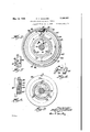
- FIG. 1 is a sectional elevation of my improved reversing switch
- Fig. 2 is an end view thereof, partly in section, looking in the direction of the arrow 2 in Fig. l;
- Fig. 3 is a sectional end elevation, taken along the line 3-3 in Fig. 1;
- Fig. 4 is a perspective view-of a double-pole switch
- Fig. 5 is a detail view of certain switch control parts, looking in the direction of the arrow 5 in Fig. 1;
- Fig. 6 is a plan view of said double-pole switch, in association with cooperating parts
- Fig. 7 is an enlarged side elevation of a locking device
- Fig. 8 is a detail sectionalview, taken alongl the line 8-8 in Fig. 2;
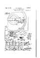
- Fig. 9 is a perspectiveview of a double-acting pilot gyrcxscope with which my reversing switch may be used;
- Fig. 10 is a. wiring diagram for said pilotgyro scope and associated switches and apparatus controlled thereby;
- Fig. 11 is a perspective view of a steering gyroscope assembly
- 'and Fig. 12 is a detail plan view, looking in the direction of the arrow I2 in Fig. 11.
- I provide a pair of rotating elements in each ⁇ gyroscopic steering unit, which elements rotate in opposite directions about axes which are normally parallel.
- the two elements thus rotating in opposite directions in the same plane, neutralize each other and, when in normal position, have no effect on the flight of the aircraft.
- the gimbals 32 'and 32B (Figs. 1l and l2) are provided with external gear teeth and are mounted for rotation on rolls or loose pinions 33E.
- a motor 35 (Fig. 12) drives a pinion 36 which engages the gimbal 32, and the pinion 36 meshes with a pinion 3l which engages and drives the second gimbal 32a.
- ri'he motor 35 is of the reversing type and ccnstitutes means by which the gimbals 32 and 32* may be simultaneously displaced angularly to any desired extent but always in opposed directions.
- Motors M and M are provided for continuously rotating the gyroscope elements 30 and 3
- the non-rotating parts of the motors M and M' are supported on cross rods or braces 39 in the gimbals 32 and 32e.
- one pair of said gyroscope elements as Sli and 3l, are moved out of their normal or hal anced inoperative relation by turning the sup-n porting ginibals in opposite directions, the di renting force then developed by the displaced gyroscopes vvill divert the aircraft trom its prior path 01' travel and will continue to divert, turn. or rotate the craft further and iurther from its normal path, such action continuing as longas the gyroscope elements remain out oi :termal or balanced inoperative position. When said elements are returned to such balanced position, the craft will continue in its new direction, un less diverted therefrom by some external torce.
- my improved gyroscopic apparat-us in this simple iorm may thus be used to steer aircraft in a desired path of travel by manual control of the steering gyroscopes
- a doubleactlng pilot gyr-oscope such as is shown in Figs. 9 and 10, and which is adapted to control two motors, as 35, which will each correct deviations of an aircraft from its path of travel in one plane.
- Each pilot gyroscope comprises a frame fixed in position in the aircraft and supporting a gini-1 bal 4l on gimbal bearings 42 and 43.
- a second girnbal 44 is mounted within the girnbal 4l on gimbal bearings 45 and 46.
- a gyroscope element 41 of substantial weight is rotatably mounted in the gimbal 44 and is provided with a driving motor 48 and a rotating counterweight 49.
- the non-rotating parts of the motor 48 are mounted on a cross brace 50 carried by the gimbal 44.
- my improved gyroscopic steering apparatus When my improved gyroscopic steering apparatus is thus automaticallycontrolled to maintain a. directed flight, it operates to displace the gimbals 32-32 in one of the gyroscope frames 33 in a certain way to offset a divergence in ight caused by a given external force and to preventv catarsi divergence in this undesired direction. It is then necessary to produce an angular correction oi the path of fright in the opposite direction to restore 'the original direction or flight.
- l1 cause a motor, as 35,13@ increasingly displace its associated eyroscope elements until the disturbing external force is overcome and neutralized.
- the night-correcting gyroscopes then continue to rotate in their new' displaced relation for a certain period, thus providing further reactive force to partially restore the craft to its original position, after which said controlling motor will be operated in the reverse direction to gradually return the light-correcting gyroscopes to their original balanced and inoperative positions.
- a block 58 (Fig. l) .oi' insulating material is xed on the pilot gyroscope frame 40 concentric with the pivot bearing 42 of the gmbal 4l.
- a plurality of rings to and 8U, El and (ile and 62 and 62S are rotatably mounted on the block 58.
- the rings S0 and tte are provided with interfoal gear teeth, meshing with pinions 63 which also engage fred. external gear teeth on the bloei; 58, and which are mounted on pivot studs t@ hired in the adjacent ring 6l or Gle. Rotation of one of the rings il@ or S will cause simul;
- pole switch 61 having an operating pin 68 secured thereto near the free ends of said fingers.
- the contact lingers 56 are adapted to contact with contact rings 69 (Fig. 6) mounted on the block 58 and concentric therewith.
- the rings 69 are segmental only, and the ends of the rings are separated by a space indicated by the letter g in Fig. 2.
- the switch 6l may be thrown from right to left as viewed in Fig. 6, and in both positions will make contact with the middle ring 69 and with one or the other of the outside rings.
- side rings are connected together as indicated in Fig. 1, so that movement of the switch from side to side will reverse the direction of current flow in the circuits controlled thereby.
- the ring 62a is similarly provided with a projection 65il supporting a double pole switch similar to the switch 61 and having an operating pin 68, and said switch having a pair of contact fingers 86 adapted to engage selected segmental rings 69a having their ends spaced apart as indicated at h in Fig. l2.
- An arm 10 (Figs. 1 and 2) is attached to the gimbal which is angularly displaceable relative l lll) The outy laterally extended portion normally seated in a.
- a spring 13 (Fig. '1) normally holds the parts yieldingly in the described relation and with the depending portion 14 of the bell crank 1
- are rotated in a direction away from the end of the fixed segmental ring 15, the parts maintain the relation shown in Figs. 1 and '1 and the ring 68 is moved with the arm 18.
- n (Fig. 1) engages and rotates the ring 68 in a direction opposite to the previously described movement of the ring 68.
- a is mounted on an arm 18a which is fixed to the same gimbal which supports the arm 18, and the bell crank is controlled in its operation by a fixed ring 15, all as previously described.
- (Fig. 5) carries a cam arm 88.!ixed thereto and projecting laterally therefrom to engage the operating pin 68 of the double pole switch 61.
- will be similarly displaced, although at different speeds, and the arm 88 will engage and shift the pin 68 to the position shown in Fig. 6.
- a second cam arm 8 I (Fig. 5) is mounted on the ring 68 and when moved in the reverse direction will shift the switch 61 to its opposite working position. Similar cam arms are associated with the rings 68 and 6
- the contact fingers 66 of the switch 61 are connected to concentric bands 83 and 84 (Fig. l) on the ring 62, which bands are'engaged by contact strips or brushes 85 and 86 on the arm 18, connected by wires 81 and 88 to brushes 88 and 98 which engage commutator rings 9
- Brushes 95 and 96 are mounted on the ring 62 and are connected to the bands 83 and 84, and said brushes engage corresponding bands 83%i and 84al on the, ring 62, which bands are connected respectively to the two contact fingers 66a of the lower switch.
- the outside segmental rings 69 and 69EL (Fig. l) are connected to a terminal 91 on the block 58, and the middle rings 69 and 651a are similarly connected to a second terminal 98. 4
- the switch ngers 66 normally rest on the non-conducting portion a of the block 58 between the ends of the segmental rings 68, but as soon as the rotation of the ring 62 is begun, the iingers engage the selected rings 68 and complete a motor control circuit which will be hereinafter described.
- the steering gyroscope motor will continue to operate, still further displacing the steering gyroscopes to produce a counter-rotation of the aircraft and a like rotation of the pilot gyroscope gimbal supporting the arm 18. 'Ihis will rotate the ring 68 in-'.the opposite direction, carrying with it theringf 6
- the main-'gen'erator or source of power G is connected through wires
- a second-generator G is connected through wires III and to commutator rings on the gimbal 4 2 of the double acting pilot gyroscopelbli'o'wn'm Fig. 9.
- 2 and H3 are mountedlon thearm 18 of the gimbal 4
- .1 are connected by wires IIS M ,.to the motor 46 which drives the constantly rotating gyroscope element 41. 'Through connections the generator G' is continuously to the motor 48 in every position o! the pilot gyroscope and its supporting gimbals.
- the .generator G' is also connected through branch wires
- a delayed action switch comprising a contact device, a first member effective to shift said device in one direction when rotated in a given direction, a second member effective to shift said device in the opposite direction when rotated in the reverse direction, and means to rotate said members in the same direction and to move one member twice as fast as the other, whereby a delayed.reverse shift of said device occurs after reversal of rotation of said members.
- a delayed action switch comprising a contact device, a rotatable member effective to engage and shift said contact device in one'direction when rotated in a primary direction but ineffective to shift said device when moved in the op- -posite secondary direction, a second rotatable member effective to engage and shift said contact device in the opposite direction when said second member is moved in said secondary direction but ineffective to shift said contact device when moved in said primary direction, and means to move said two rotatable members simultaneously in the same direction but at substantially different speeds.
- a delayed action switch comprising a contact device, segmental conducting rings selectively engaged by said device, a relatively fixed support for said rings, first, second and third members movably mounted on said support, said third member supporting said contact device, means on said first member to shift said device in one direction, means on said second member to shift said device i'n the opposite direction, means to move said first member angularly on said support, and connections between said first and second members through which said first member drives said second member in the same direction but at reduced speed.
- a delayed action switch comprising a contact device, segmental conducting rings selectively engaged by said device and having an adjacent insulating surface on which said devices normally rest, a cylindrical and relatively fixed support for said rings, first, second and third members rotatably mounted on said support, said third member supporting said contact device, means on said first member to shift said device in one direction, means on said second member to Shift said device in the opposite direction, means to partially rotate said first member on said support, and connections between said first and second'members through which said first member when rotated in either direction rotates said second member in the same direction but at onehalf of the speed of said first member.
- a delayed action switch comprising a contact device, spaced segmental conducting rings selectively engaged by said device, a cylindrical support for said rings, first, second and third members rotatably mounted on said support, said third member supporting said contact device and being frictionally retarded on said support, means on said first member to shift said device in one direction, means on said second member to shift said device in the opposite direction, means to move said first member angularly on said support, and planetary gearing between said first and second members ,through which said first member when moved in either direction moves said second member in the same direction but at one-half the speed and for one-half the distance.
- a cylindrical support first, second and third members rotatably mounted on said support; a contact device on said third member, a cam arm on said second member effective' to shift said device in one direction and to thereafter rotate ⁇ said third member with said second member, a cam arm on said first member effective to shift said device in the opposite direction and to thereafter ⁇ return said third member with said first and second l members to initial position, and means to rotate said first and second members in the same direction at different speeds but in a fixed speed ratio.
- a cylindrical support first, second and third members rotatably mounted on said support, a contact device on said third membena cam arm on said second member effective to shift said device in one direction and to thereafter rotate said third member with said second member, a cam arm on said first member effective to shift said device in the opposite direction and to thereafter return said third member with said first and second members to initial position, means to rotate said first and second members in the same direction at different speeds but in a fixed speed ratio, angularly movable driving means for said first member, and'means to lock said driving means to said first member when said driving means is moved in one direction only.
Landscapes
- Physics & Mathematics (AREA)
- Engineering & Computer Science (AREA)
- General Physics & Mathematics (AREA)
- Radar, Positioning & Navigation (AREA)
- Remote Sensing (AREA)
- Mechanical Control Devices (AREA)
Description
May 16, 1939. R. H. GODDARD DELAYED ACTION REVERSING SWITCH 3 sheetssheet 1 Original Filed Nov. 9, 1956 May 16, 1939. R GODDARD DELAYED ACTION REvERsING s-wITcH Original Filed Nv. 9, 1936 5 Sheets-Sheet? wila-...V
May 16, 1939. R4 H, GODDARD 2,158,181
l DELAYED ACTION REVERSING SWITCH Original Filed Nov. 9, 1956 3 Sheets-Sheet 3 f '101. 9&7 22
Patented May 16, 1939 UNITED STATES PATENT OFFICE Divided and this application July 10,
1937, Serial No. 153,009
8 Claims.
This application is a division of my prior application Serial No. 109,964, led November 9, 1936 on Gyroscopic steering apparatus.
The present application relates to a delayed action reversing switch, fully shown and described in said original application. My improved switch is capable of general application but is particularly designed for use with night-directing gyroscopic apparatus.
It is the general object of my invention to provide a delayed action reversing switch by which current may. be caused to flow through an electric circuit in one direction for a certain period of time and may be caused to flow through said circuit in the opposite direction for another period of time but only after a predetermined neutral interval.
A further object is to provide a switch in which the reverse operating period will always be in fixed proportion to the initial operating period, regardless of `the length of said initial period.
My invention further relates to arrangements and combinations of parts which will be hereinafter described and more particularly pointed out in the appended claims.
A preferred form of the invention is shown in the drawings, in which Fig. 1 is a sectional elevation of my improved reversing switch;
Fig. 2 is an end view thereof, partly in section, looking in the direction of the arrow 2 in Fig. l;
Fig. 3 is a sectional end elevation, taken along the line 3-3 in Fig. 1;
Fig. 4 is a perspective view-of a double-pole switch;
Fig. 5 is a detail view of certain switch control parts, looking in the direction of the arrow 5 in Fig. 1;
Fig. 6 is a plan view of said double-pole switch, in association with cooperating parts;
Fig. 7 is an enlarged side elevation of a locking device;
Fig. 8 is a detail sectionalview, taken alongl the line 8-8 in Fig. 2;
Fig. 9 is a perspectiveview of a double-acting pilot gyrcxscope with which my reversing switch may be used;
Fig. 10 is a. wiring diagram for said pilotgyro scope and associated switches and apparatus controlled thereby;
Fig. 11 is a perspective view of a steering gyroscope assembly; 'and Fig. 12 is a detail plan view, looking in the direction of the arrow I2 in Fig. 11.
.(Cl. D-33) In the development of the improved gyroscopic steering apparatus, for the control of which my improved switch is particularly designed, I make use of the known principle that a heavy ring rotating on an axis in a supporting structure and in a plane perpendicular to the axis of said supporting structure will produce a reacting force tending to rotate said supporting structure in a reverse direction, which rotation will actually take place if the supporting structure is itself mounted for free rotation.
Preferably, I provide a pair of rotating elements in each` gyroscopic steering unit, which elements rotate in opposite directions about axes which are normally parallel. The two elements, thus rotating in opposite directions in the same plane, neutralize each other and, when in normal position, have no effect on the flight of the aircraft.
Such an arrangement is indicated in Figs. 11
and 12 in which rotating elements 30 and 3| are mounted in gimbals 32 and 32n in a frame 33. So long as the parts are in the position shown ln Fig. 11, the frame 33 will remain at rest. If, however, the giinbals are moved simultaneously in opposite directions to' bring the rotating elements and 3| to oppositely inclined positions, an angular momentum will be produced by the rotating elements, and the accompanying reactive force on the supporting frame 33 will tend to produce angular movement thereof. This reactive force is a maximum when the gimbals 32 and 32 are each rotated 90, but any iangular' displacement of the two gimbals and rotated elements simultaneously in opposed directions will produce a substantial angular reaction, which reaction increases with the angle of displacement.
The gimbals 32 'and 32B (Figs. 1l and l2) are provided with external gear teeth and are mounted for rotation on rolls or loose pinions 33E. A motor 35 (Fig. 12) drives a pinion 36 which engages the gimbal 32, and the pinion 36 meshes with a pinion 3l which engages and drives the second gimbal 32a.
Motors M and M are provided for continuously rotating the gyroscope elements 30 and 3|, and corresponding rotating counterbalances 38 are also provided. The non-rotating parts of the motors M and M' are supported on cross rods or braces 39 in the gimbals 32 and 32e.
If it is now assumed that the frame 33 is xed in position in an aircraft and the rotated elements are displaced, the reaction or the die11 placed gyroscopic elements will tc aircrzdt in a definite direction. and rotated elements are theres the reverse direction, the reaction rf versed and the will be opposite direction.
It is thus possible to control the movements oi an in vertical and horizontal planes and also about its own axis, by providing three pairs oi rotating gyroscopic elements, each pair operating in perpendicidarly disposed relation to the other two pairs.
.-.i one pair of said gyroscope elements, as Sli and 3l, are moved out of their normal or hal anced inoperative relation by turning the sup-n porting ginibals in opposite directions, the di renting force then developed by the displaced gyroscopes vvill divert the aircraft trom its prior path 01' travel and will continue to divert, turn. or rotate the craft further and iurther from its normal path, such action continuing as longas the gyroscope elements remain out oi :termal or balanced inoperative position. When said elements are returned to such balanced position, the craft will continue in its new direction, un less diverted therefrom by some external torce.
For a more complete description this general method oi flight control, reference is made to the original application oi which this a division.
While my improved gyroscopic apparat-us in this simple iorm may thus be used to steer aircraft in a desired path of travel by manual control of the steering gyroscopes, the invention is more broadly useful when associated with gyro= scopic control devices or pilot gyroscopes, by the action oi which an aircraft, when diverted from its path o travel by external force, will be automatically returned to its original path of travel.
For this purpose preferably provide a doubleactlng pilot gyr-oscope such as is shown in Figs. 9 and 10, and which is adapted to control two motors, as 35, which will each correct deviations of an aircraft from its path of travel in one plane.
Each pilot gyroscope comprises a frame fixed in position in the aircraft and supporting a gini-1 bal 4l on gimbal bearings 42 and 43. A second girnbal 44 is mounted within the girnbal 4l on gimbal bearings 45 and 46. A gyroscope element 41 of substantial weight is rotatably mounted in the gimbal 44 and is provided with a driving motor 48 and a rotating counterweight 49. The non-rotating parts of the motor 48 are mounted on a cross brace 50 carried by the gimbal 44.
Whenever the aircraft is diverted from its normal course in either of the two directions controlled by the gyroscope element 41, said element will continue to rotate in its normal plane, but the supporting gimbals 44 and 4I will be displaced relative to each other and also relative to the iixed frame 40, and by suitable electrical connections they will determine the operation of the motors which rotate the gimbals of the directing or steering gyroscopes controlled thereby.
When my improved gyroscopic steering apparatus is thus automaticallycontrolled to maintain a. directed flight, it operates to displace the gimbals 32-32 in one of the gyroscope frames 33 in a certain way to offset a divergence in ight caused by a given external force and to preventv catarsi divergence in this undesired direction. It is then necessary to produce an angular correction oi the path of fright in the opposite direction to restore 'the original direction or flight.
is particularly desirable to prevent overcorrection, which would cause an irregular, vrabbling or oscillating flight.
lior such automatic control, l1 cause a motor, as 35,13@ increasingly displace its associated eyroscope elements until the disturbing external force is overcome and neutralized. The night-correcting gyroscopes then continue to rotate in their new' displaced relation for a certain period, thus providing further reactive force to partially restore the craft to its original position, after which said controlling motor will be operated in the reverse direction to gradually return the light-correcting gyroscopes to their original balanced and inoperative positions.
In order to effect the described series or oper- .y
ations of the steering gyroscope motor, l have devised the delayed action reversing switch shown in detail in. l to il and which will now be described.
A block 58 (Fig. l) .oi' insulating material is xed on the pilot gyroscope frame 40 concentric with the pivot bearing 42 of the gmbal 4l. A plurality of rings to and 8U, El and (ile and 62 and 62S are rotatably mounted on the block 58.
The rings S0 and tte are provided with interfoal gear teeth, meshing with pinions 63 which also engage fred. external gear teeth on the bloei; 58, and which are mounted on pivot studs t@ hired in the adjacent ring 6l or Gle. Rotation of one of the rings il@ or S will cause simul;
The contact lingers 56 are adapted to contact with contact rings 69 (Fig. 6) mounted on the block 58 and concentric therewith. The rings 69 are segmental only, and the ends of the rings are separated by a space indicated by the letter g in Fig. 2.
The switch 6l may be thrown from right to left as viewed in Fig. 6, and in both positions will make contact with the middle ring 69 and with one or the other of the outside rings. side rings are connected together as indicated in Fig. 1, so that movement of the switch from side to side will reverse the direction of current flow in the circuits controlled thereby.
The ring 62a is similarly provided with a projection 65il supporting a double pole switch similar to the switch 61 and having an operating pin 68, and said switch having a pair of contact fingers 86 adapted to engage selected segmental rings 69a having their ends spaced apart as indicated at h in Fig. l2.
An arm 10 (Figs. 1 and 2) is attached to the gimbal which is angularly displaceable relative l lll) The outy laterally extended portion normally seated in a.
slot 12 (Fig. 3) in the periphery of the ring 60. so that the ring G0 is normally held in flxed angular relation to the arm 18 and its supporting gimbal.
A spring 13 (Fig. '1) normally holds the parts yieldingly in the described relation and with the depending portion 14 of the bell crank 1| in alignment with a segmental ring 15 (Fig. 8) fixed on the end of the block 58. When the arm 18 and bell crank 1| are rotated in a direction away from the end of the fixed segmental ring 15, the parts maintain the relation shown in Figs. 1 and '1 and the ring 68 is moved with the arm 18.
If the arm 18 is displaced in the opposite direction, however, the depending arm 14 engages a beveled end surface 16 (Fig. 8) ofthe ring l5 and is swung clockwise out of the slot 12, thus causing no movement of the ring 68.
lWhen the parts are thus operated, however, a corresponding be1l crank 1|n (Fig. 1) engages and rotates the ring 68 in a direction opposite to the previously described movement of the ring 68. The bell crank 1|a is mounted on an arm 18a which is fixed to the same gimbal which supports the arm 18, and the bell crank is controlled in its operation by a fixed ring 15, all as previously described.
The ring 6| (Fig. 5) carries a cam arm 88.!ixed thereto and projecting laterally therefrom to engage the operating pin 68 of the double pole switch 61. When the gimbal which supports the arm 18 is displaced angularly in the direction indicated by the arrow k in Fig. 5, the rings 68 and 6| will be similarly displaced, although at different speeds, and the arm 88 will engage and shift the pin 68 to the position shown in Fig. 6.
A second cam arm 8 I (Fig. 5) is mounted on the ring 68 and when moved in the reverse direction will shift the switch 61 to its opposite working position. Similar cam arms are associated with the rings 68 and 6|a and similarly engage the pin 68' and operate the switch fingers 66a.
The contact fingers 66 of the switch 61 are connected to concentric bands 83 and 84 (Fig. l) on the ring 62, which bands are'engaged by contact strips or brushes 85 and 86 on the arm 18, connected by wires 81 and 88 to brushes 88 and 98 which engage commutator rings 9| and 82 mounted on an extension of the block 58 and connected to binding posts 93 and 84.
The operation of the delayed action switch mechanism above described is as follows:
When the gimbal supporting the arm 18 is displaced in the direction of the arrow k in Fig. 5, the ring 68 is similarly displaced and the ring 6| is moved in the same direction but for onehalf the distance. rSuch movement causes the cam arm 88 to shift the switch 61 to the positionshown in Fig. 6. `After having shifted the switch, the arm 88 continues to push against the pin 68, thus rotating the ring 62 with the arm 88.
The switch ngers 66 normally rest on the non-conducting portion a of the block 58 between the ends of the segmental rings 68, but as soon as the rotation of the ring 62 is begun, the iingers engage the selected rings 68 and complete a motor control circuit which will be hereinafter described.
The motion of the arm 18 and ring 68 and the haii'. speed motion of the rings 6| and 62 continue until the corresponding steering gyroscope has equalized the deviating force and thus stopped the relative angular movement of the gimbal which supports the arm 18.
The steering gyroscope motor will continue to operate, still further displacing the steering gyroscopes to produce a counter-rotation of the aircraft and a like rotation of the pilot gyroscope gimbal supporting the arm 18. 'Ihis will rotate the ring 68 in-'.the opposite direction, carrying with it theringf 6| at half speed, but the ring 62 supporting the switch 61 will be held frictionally in fixedv` position until the pin 68 is engaged by the cam arm 8|.
As the arrrrll`r has traveled twice as fast and twice as farfasfthe pin 68 in the initial direction, the .will not reverse the switch 61 until halt cfg, V`return movement has been completed. the switch 61 will be reversed be returned to initial position along` yvij1t-`tl-e ring 62.
When th Witch is reversed, the control circuit of thelniownwhich shifts the steering gyroscope is rcversedand the gyroscope elements are gradually-brought back to initial inoperative relation, thisa'ult being accomplished at the same time;y that the ring 62 is returned to its original position and the control circuit is broken by separationv of the contact fingers 66 from the segmental rings 69.
If the initial movement of the arms 18 and 18 is in the opposite direction, the corresponding parts at the Yleift in Fig. 1 will be similarlyoperated to correct a deviation in the opposite direction.
The electrical circuits and connections through which my improved switch connects a pilot gyroscope to control a steering gyroscope are shown diagrammaticallyin Fig. 10.V
The main-'gen'erator or source of power G is connected through wires |88 and |8I, a relay R and wires illffsan'd |83 to a motor, as 35, (Fig. l2) which rotate@ the gimbal frames 32 and 82* of the steerig'gyroscope shown in Fig. 11.
A second-generator G is connected through wires III and to commutator rings on the gimbal 4 2 of the double acting pilot gyroscopelbli'o'wn'm Fig. 9. Brushes l|2 and H3 are mountedlon thearm 18 of the gimbal 4| and are connected liywires ||4 and ||5 to commutator rings on .the gimbal bearing 46, which rings are engaged by brushes H6 and I1 mounted on anvv amig-H8 on the inner gimbal ring 44. The brullen'v 1116. and ||.1 are connected by wires IIS M ,.to the motor 46 which drives the constantly rotating gyroscope element 41. 'Through connections the generator G' is continuously to the motor 48 in every position o! the pilot gyroscope and its supporting gimbals.
The .generator G' is also connected through branch wires |21 and |22 to the segmental rings 68 previously described, which rings are selectively engaged by contact fingers of the switch 61 to complete a control circuit through the brushes I5 and 86, wires 81 and 88, brushes 88 gimbal 4| from its normal relation to the frame- 48 causes the relay R to be operated in such xnanner as to connect the generator G to the motor 35 and thus cause rotation thereof in one direction.
For the sake of clearness, the connections through the segmental rings 69EL and switch 61a are omitted, these being duplicates of the circuits previously described and being connected to cause the relay R to complete reverse connections between the generator G and the motor 35, so that the motor will operate in the opposite direction.
With the connections described, it will be evident that the motor 35 which controls one of the steering gyroscopes will be operated in accordance with the displacement of the gimbal 4l relative to the supporting frame 40, and that the operation of a second steering gyroscope will be in accordance with the displacement of the gimbal 44 relative to the gimbal 4I.
Having fully described the details of construction of my improved delayed action switch and its utility in connection withfgyroscopiccontrol apparatus, it is believed that the operation and advantages of my invention will be readily apparent. I do not wish to be limited to the details herein disclosed, otherwise than as set forth in the claims, but what I claim is:
1. A delayed action switch comprising a contact device, a first member effective to shift said device in one direction when rotated in a given direction, a second member effective to shift said device in the opposite direction when rotated in the reverse direction, and means to rotate said members in the same direction and to move one member twice as fast as the other, whereby a delayed.reverse shift of said device occurs after reversal of rotation of said members.
2. The combination in a delayed action switch as set forth in claim l, in which the contact device is mounted on a third rotatable member which is held frictionally at rest between engagements by said members.
3. A delayed action switch comprising a contact device, a rotatable member effective to engage and shift said contact device in one'direction when rotated in a primary direction but ineffective to shift said device when moved in the op- -posite secondary direction, a second rotatable member effective to engage and shift said contact device in the opposite direction when said second member is moved in said secondary direction but ineffective to shift said contact device when moved in said primary direction, and means to move said two rotatable members simultaneously in the same direction but at substantially different speeds.
4. A delayed action switch comprising a contact device, segmental conducting rings selectively engaged by said device, a relatively fixed support for said rings, first, second and third members movably mounted on said support, said third member supporting said contact device, means on said first member to shift said device in one direction, means on said second member to shift said device i'n the opposite direction, means to move said first member angularly on said support, and connections between said first and second members through which said first member drives said second member in the same direction but at reduced speed.
5. A delayed action switch comprising a contact device, segmental conducting rings selectively engaged by said device and having an adjacent insulating surface on which said devices normally rest, a cylindrical and relatively fixed support for said rings, first, second and third members rotatably mounted on said support, said third member supporting said contact device, means on said first member to shift said device in one direction, means on said second member to Shift said device in the opposite direction, means to partially rotate said first member on said support, and connections between said first and second'members through which said first member when rotated in either direction rotates said second member in the same direction but at onehalf of the speed of said first member.
6. A delayed action switch comprising a contact device, spaced segmental conducting rings selectively engaged by said device, a cylindrical support for said rings, first, second and third members rotatably mounted on said support, said third member supporting said contact device and being frictionally retarded on said support, means on said first member to shift said device in one direction, means on said second member to shift said device in the opposite direction, means to move said first member angularly on said support, and planetary gearing between said first and second members ,through which said first member when moved in either direction moves said second member in the same direction but at one-half the speed and for one-half the distance.
7. In a delayed action reversing switch, a cylindrical support, first, second and third members rotatably mounted on said support; a contact device on said third member, a cam arm on said second member effective' to shift said device in one direction and to thereafter rotate` said third member with said second member, a cam arm on said first member effective to shift said device in the opposite direction and to thereafter `return said third member with said first and second l members to initial position, and means to rotate said first and second members in the same direction at different speeds but in a fixed speed ratio.
8. In a delayed action reversing switch, a cylindrical support, first, second and third members rotatably mounted on said support, a contact device on said third membena cam arm on said second member effective to shift said device in one direction and to thereafter rotate said third member with said second member, a cam arm on said first member effective to shift said device in the opposite direction and to thereafter return said third member with said first and second members to initial position, means to rotate said first and second members in the same direction at different speeds but in a fixed speed ratio, angularly movable driving means for said first member, and'means to lock said driving means to said first member when said driving means is moved in one direction only.
ROBERT H. GODDARD.
Zin
Priority Applications (1)
| Application Number | Priority Date | Filing Date | Title |
|---|---|---|---|
| US153009A US2158181A (en) | 1936-11-09 | 1937-07-10 | Delayed action reversing switch |
Applications Claiming Priority (2)
| Application Number | Priority Date | Filing Date | Title |
|---|---|---|---|
| US109964A US2158180A (en) | 1936-11-09 | 1936-11-09 | Gyroscopic steering apparatus |
| US153009A US2158181A (en) | 1936-11-09 | 1937-07-10 | Delayed action reversing switch |
Publications (1)
| Publication Number | Publication Date |
|---|---|
| US2158181A true US2158181A (en) | 1939-05-16 |
Family
ID=26807567
Family Applications (1)
| Application Number | Title | Priority Date | Filing Date |
|---|---|---|---|
| US153009A Expired - Lifetime US2158181A (en) | 1936-11-09 | 1937-07-10 | Delayed action reversing switch |
Country Status (1)
| Country | Link |
|---|---|
| US (1) | US2158181A (en) |
Cited By (2)
| Publication number | Priority date | Publication date | Assignee | Title |
|---|---|---|---|---|
| US2466055A (en) * | 1946-05-15 | 1949-04-05 | Jr Theodore E Sierer | Rotary signal pick-off control means |
| US2471651A (en) * | 1946-11-08 | 1949-05-31 | Anthony F Pantuosco | Automatic ignition shutoff device |
-
1937
- 1937-07-10 US US153009A patent/US2158181A/en not_active Expired - Lifetime
Cited By (2)
| Publication number | Priority date | Publication date | Assignee | Title |
|---|---|---|---|---|
| US2466055A (en) * | 1946-05-15 | 1949-04-05 | Jr Theodore E Sierer | Rotary signal pick-off control means |
| US2471651A (en) * | 1946-11-08 | 1949-05-31 | Anthony F Pantuosco | Automatic ignition shutoff device |
Similar Documents
| Publication | Publication Date | Title |
|---|---|---|
| US1393456A (en) | Orientator | |
| US1747664A (en) | Apparatus for automatically training guns, etc., on moving objects | |
| US2014825A (en) | Stabilizing means for a body subjected to the influence of angular motion | |
| US2158180A (en) | Gyroscopic steering apparatus | |
| US2271296A (en) | Course-indicating apparatus for vehicles | |
| US2158181A (en) | Delayed action reversing switch | |
| US1957240A (en) | Control system | |
| US2542975A (en) | Erecting mechanism for reducing turn errors in vertical gyroscopes | |
| US2383409A (en) | Controlling means for gyroscopes | |
| US3473024A (en) | X-ray tabletop extension and tilt control | |
| US1333588A (en) | Selvage-trimmer | |
| US1016240A (en) | Apparatus for steering moving objects, particularly ships and flying-machines. | |
| US2559339A (en) | Remote-control system | |
| US3863363A (en) | Planetarium | |
| US2580748A (en) | Centering and caging mechanism for gyroscopes | |
| US2054224A (en) | Remote control for directing projected light | |
| US1701398A (en) | Periodic switching mechanism | |
| US2098296A (en) | Planetarium | |
| US2425737A (en) | Gyroscope controlled antenna stabilizer | |
| US2183314A (en) | Gyroscopic apparatus for directing flight | |
| US1850598A (en) | Searchlight control | |
| US2340174A (en) | Automatic steering system | |
| US1747279A (en) | Adjustable projector | |
| US3326552A (en) | Apparatus to serve in game, toy, educational and display devices | |
| US1322704A (en) | System fob operating doobs |