US2155195A - Adjustable thrust bearing for valve springs - Google Patents
Adjustable thrust bearing for valve springs Download PDFInfo
- Publication number
- US2155195A US2155195A US107813A US10781336A US2155195A US 2155195 A US2155195 A US 2155195A US 107813 A US107813 A US 107813A US 10781336 A US10781336 A US 10781336A US 2155195 A US2155195 A US 2155195A
- Authority
- US
- United States
- Prior art keywords
- valve
- spring
- cylinder
- thrust bearing
- adjustable thrust
- Prior art date
- Legal status (The legal status is an assumption and is not a legal conclusion. Google has not performed a legal analysis and makes no representation as to the accuracy of the status listed.)
- Expired - Lifetime
Links
- 239000012530 fluid Substances 0.000 description 8
- 230000006835 compression Effects 0.000 description 5
- 238000007906 compression Methods 0.000 description 5
- 230000003137 locomotive effect Effects 0.000 description 3
- 230000000694 effects Effects 0.000 description 1
- 238000012423 maintenance Methods 0.000 description 1
- 238000012986 modification Methods 0.000 description 1
- 230000004048 modification Effects 0.000 description 1
- 210000000056 organ Anatomy 0.000 description 1
- 238000012856 packing Methods 0.000 description 1
- 238000009877 rendering Methods 0.000 description 1
Images
Classifications
-
- F—MECHANICAL ENGINEERING; LIGHTING; HEATING; WEAPONS; BLASTING
- F01—MACHINES OR ENGINES IN GENERAL; ENGINE PLANTS IN GENERAL; STEAM ENGINES
- F01L—CYCLICALLY OPERATING VALVES FOR MACHINES OR ENGINES
- F01L31/00—Valve drive, valve adjustment during operation, or other valve control, not provided for in groups F01L15/00 - F01L29/00
- F01L31/08—Valve drive or valve adjustment, apart from tripping aspects; Positively-driven gear
- F01L31/16—Valve drive or valve adjustment, apart from tripping aspects; Positively-driven gear the drive being effected by specific means other than eccentric, e.g. cams; Valve adjustment in connection with such drives
Definitions
- My invention relates to an adjustable thrust bearing for valve springs.
- the distributing valves for steam and like engines (the opening control of which is effected by means of cams of any shape and of any convenient arrangement), generally speaking, are provided with return springs.
- Such springs must have a very high strength because of the dimensions of the valves and o-f the necessary high speeds o-f operation. It follows that when said valves or their controlling members are to be operated, for example to effect reversing (this adjustment being made while the machine is not operating), a very special effort must be applied to overpower the compression force of the springs.
- an adjustable thrust bearing or reaction abutment is provided for each spring and is equipped with a controlling member, operating either directly or indirectly, such as a piston or the like which may be displaced in a convenient chamber, such as a cylinder, in which it is subjected to a pressure (resilient or otherwise) higher than that which is exertable by the associated valve spring, so as. to permit said spring to be distended by virtue of the temporary relieving of the spring pressure (either manually or automatically), thus rendering easier the control of said valve while securing the convenient maintenance of the compression force of the springs during the normal operation of the machine.
- a controlling member operating either directly or indirectly, such as a piston or the like which may be displaced in a convenient chamber, such as a cylinder, in which it is subjected to a pressure (resilient or otherwise) higher than that which is exertable by the associated valve spring, so as. to permit said spring to be distended by virtue of the temporary relieving of the spring pressure (either manually or automatically), thus rendering easier the control of said valve while
- the coil spring I which acts at one end upon a socket 2 adapted to be associated with an end of the valve stem I5, serves to control the closure of the valve I4.
- This valve works in the chest I5 having a passage I3 ccmmunicating with cylinder I2 in which one of the pistons o-f the locomotive II is mounted.
- the opening movement of the valve may be eifected by means of a cam 20 mounted on shaft ZI, the cam bearing on a roller or follower I9 carried by a lever which is pivoted at IB, the free end I'I of which is adapted to abut an end of the valve stem I6.
- the foregoing valve and cam actuating mechanism is of a general type known in this art and is described only briefly since the specific features thereof form no part of the present invention per se.
- valve closing spring I remote from the valve I4 is held in a cup 3, constituting a thrust bearing or reaction abutmentl for the spring which is sldably mounted in a chamber 4 of any convenient arrangement.
- a central part 5 of the cup 3 receives the end of the stem 6 of a piston 1 located in cylinder 8 which communicates through a port 9 with a convenient source of any fluid under pressure shown, by Way of example, at 34.
- a member, such as a cock, valve or the like, illustrated at 35 may be operated from the operators post of the machine, is located in the pipe which feeds cylinder 8 in such a manner as, in one position, to cut off the communication of said cylinder 8 with the source of fluid under pressure and, in another position, to bring said cylinder 8 into communication with the atmosphere.
- Said cock or the like may be connected by any convenient means with the other control organs for the machine, such for example as the steam governor, or reversing gear, in order to obtain wholly or partially automatic operation.
- a drain port I0 provided with a convenient obturator, is located at the end of cylinder 8 remote from port 9.
- valve is, of course, loaded by spring I, the member or socket 2 engaging the valve stem and thus receiving the cam thrust during actuation of the valve.
- the piston 1 is kept rigidly in the position shown in the drawing by the pressure existing in cylinder 8, the whole device thus operating as if spring I were held on the end of a stationary stem.
- the uid pressure which acts in cylinder 8 is, of course, sunicent for constantly keeping the effort exerted by said pressure upon piston 1 higher than the highest possible compression force of spring I.
- each cylinder 8 When it is desired to adjust the mechanism so as to vary the operation of the valves, for example through cams, the communication between each cylinder 8 and the corresponding source of fluid under pressure is cut off, this being accomplished by movement of valve to its position in which the cylinder 8 is Vented. Thereby the cylinders are brought into communication with the atmosphere, and this causes a fall in pressure to take place in said cylinders.
- Each piston 'I is thus forced by its spring I towards the end of cylinder 8, from a position in which said spring I possesses only a very small or no compression force, so that the member which controls the valvesmay be displaced easily and with small eifort.
- 'I'he fluid which is ⁇ used for keeping piston 'l in the position providing compression of spring I could be steam, in the case of a steam engine, but said iiuid can also be any fluid underl pressure, resilient or otherwise, and the cylinder 8 either may be kept in constant communication with the source during operation of the engine, or said cylinder may be isolated by adjustment of some other convenient device.
- My invention relates to distributing devices provided With valves either of horizontal, vertical or inclined type, for steam engines designed for locomotives, naval engines or the like.
- valve closing spring associated with said member, a reaction abutment for said spring mounted for movement in the direction, of reaction of the: spring, and means normally retaining the abutment in a position to maintain the valve closing force of the spring, said means being releasable to relieve the pressure of the spring on the valve.
- actuating and controlling mechanism for a steam engine distribution Valve having a con.- trollable cut-oli ⁇ cam operating means, a member receiving the cam thrust during operation, there'- of, a valve closing spring associated with said member, a reaction abutment for said spring mounted for movement in the direction of reaction of the spring, and means normally retaining the abutment in a position to maintain ⁇ the valve closing force oi the spring, said means including a fluid pressure piston and cylinder device associated with the abutment and operative to maintain the valve closing force of the: spring upon admission of fluid to the cylinder of said device and upon exhaust of fluid from the cylinder' to relieve the pressure of the spring on the valve.
Landscapes
- Engineering & Computer Science (AREA)
- Mechanical Engineering (AREA)
- General Engineering & Computer Science (AREA)
- Mechanically-Actuated Valves (AREA)
Description
April 18, 1939. J. KIRCHHOF ADJUSTABLE THRUST BEARING FOR VALVE SPRINGS Filed OCL. 27, 1936 lNyENToR d- ATTORNEYS Patented Apr. 18, 1939 PATENT OFFICE ADJUSTABLE THRUST BEARING FOR VALVE SPRINGS Julius Kirchhof, Paris, France, assigner to rm Societe dExploitaticn des Procedes Dabeg,
Paris, France Application October 27, 1936, Serial No. 107,813
In France October 28, 1935 y 2 Claims.
My invention relates to an adjustable thrust bearing for valve springs.
The distributing valves for steam and like engines (the opening control of which is effected by means of cams of any shape and of any convenient arrangement), generally speaking, are provided with return springs. Such springs must have a very high strength because of the dimensions of the valves and o-f the necessary high speeds o-f operation. It follows that when said valves or their controlling members are to be operated, for example to effect reversing (this adjustment being made while the machine is not operating), a very special effort must be applied to overpower the compression force of the springs.
According to my invention, which overcomes the above difficulty, an adjustable thrust bearing or reaction abutment is provided for each spring and is equipped with a controlling member, operating either directly or indirectly, such as a piston or the like which may be displaced in a convenient chamber, such as a cylinder, in which it is subjected to a pressure (resilient or otherwise) higher than that which is exertable by the associated valve spring, so as. to permit said spring to be distended by virtue of the temporary relieving of the spring pressure (either manually or automatically), thus rendering easier the control of said valve while securing the convenient maintenance of the compression force of the springs during the normal operation of the machine.
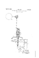
How the foregoing is accomplished is illustrated in the accompanying drawing showing, by way of example, an embodiment of the preferred constructional form of the adjustable thrust bearing of my invention, said embodiment illustrating the application of a thrust bearing to a valve device of a locomotive of a known type.
In the drawing, the coil spring I, which acts at one end upon a socket 2 adapted to be associated with an end of the valve stem I5, serves to control the closure of the valve I4. This valve works in the chest I5 having a passage I3 ccmmunicating with cylinder I2 in which one of the pistons o-f the locomotive II is mounted. The opening movement of the valve may be eifected by means of a cam 20 mounted on shaft ZI, the cam bearing on a roller or follower I9 carried by a lever which is pivoted at IB, the free end I'I of which is adapted to abut an end of the valve stem I6. The foregoing valve and cam actuating mechanism is of a general type known in this art and is described only briefly since the specific features thereof form no part of the present invention per se.
The end of the valve closing spring I remote from the valve I4 is held in a cup 3, constituting a thrust bearing or reaction abutmentl for the spring which is sldably mounted in a chamber 4 of any convenient arrangement.
A central part 5 of the cup 3 receives the end of the stem 6 of a piston 1 located in cylinder 8 which communicates through a port 9 with a convenient source of any fluid under pressure shown, by Way of example, at 34. A member, such as a cock, valve or the like, illustrated at 35, may be operated from the operators post of the machine, is located in the pipe which feeds cylinder 8 in such a manner as, in one position, to cut off the communication of said cylinder 8 with the source of fluid under pressure and, in another position, to bring said cylinder 8 into communication with the atmosphere. Said cock or the like may be connected by any convenient means with the other control organs for the machine, such for example as the steam governor, or reversing gear, in order to obtain wholly or partially automatic operation.
Convenient packings are provided around piston 1 and also around the rod 6. A drain port I0, provided with a convenient obturator, is located at the end of cylinder 8 remote from port 9.
During normal operation, the valve is, of course, loaded by spring I, the member or socket 2 engaging the valve stem and thus receiving the cam thrust during actuation of the valve. The piston 1 is kept rigidly in the position shown in the drawing by the pressure existing in cylinder 8, the whole device thus operating as if spring I were held on the end of a stationary stem.
The uid pressure which acts in cylinder 8 is, of course, sunicent for constantly keeping the effort exerted by said pressure upon piston 1 higher than the highest possible compression force of spring I.
When it is desired to adjust the mechanism so as to vary the operation of the valves, for example through cams, the communication between each cylinder 8 and the corresponding source of fluid under pressure is cut off, this being accomplished by movement of valve to its position in which the cylinder 8 is Vented. Thereby the cylinders are brought into communication with the atmosphere, and this causes a fall in pressure to take place in said cylinders. Each piston 'I is thus forced by its spring I towards the end of cylinder 8, from a position in which said spring I possesses only a very small or no compression force, so that the member which controls the valvesmay be displaced easily and with small eifort.
'I'he fluid which is` used for keeping piston 'l in the position providing compression of spring I could be steam, in the case of a steam engine, but said iiuid can also be any fluid underl pressure, resilient or otherwise, and the cylinder 8 either may be kept in constant communication with the source during operation of the engine, or said cylinder may be isolated by adjustment of some other convenient device.
While I have illustrated only a single form of mechanism embodying the invention, it will be understood that modifications may be made Without departing from the spirit of the invention.
My invention relates to distributing devices provided With valves either of horizontal, vertical or inclined type, for steam engines designed for locomotives, naval engines or the like.
What I claim is:-
1. In actuating and controlling mechanism for a steam engine distribution valve having a controllable cut-off cam operating means, a-
member receiving the cam thrust during operation thereof, a valve closing spring associated with said member, a reaction abutment for said spring mounted for movement in the direction, of reaction of the: spring, and means normally retaining the abutment in a position to maintain the valve closing force of the spring, said means being releasable to relieve the pressure of the spring on the valve.
2. In actuating and controlling mechanism for a steam engine distribution Valve having a con.- trollable cut-oli` cam operating means, a member receiving the cam thrust during operation, there'- of, a valve closing spring associated with said member, a reaction abutment for said spring mounted for movement in the direction of reaction of the spring, and means normally retaining the abutment in a position to maintain` the valve closing force oi the spring, said means including a fluid pressure piston and cylinder device associated with the abutment and operative to maintain the valve closing force of the: spring upon admission of fluid to the cylinder of said device and upon exhaust of fluid from the cylinder' to relieve the pressure of the spring on the valve.
JULIUS KIRCHHOF.
Applications Claiming Priority (1)
| Application Number | Priority Date | Filing Date | Title |
|---|---|---|---|
| FR2155195X | 1935-10-28 |
Publications (1)
| Publication Number | Publication Date |
|---|---|
| US2155195A true US2155195A (en) | 1939-04-18 |
Family
ID=9684201
Family Applications (1)
| Application Number | Title | Priority Date | Filing Date |
|---|---|---|---|
| US107813A Expired - Lifetime US2155195A (en) | 1935-10-28 | 1936-10-27 | Adjustable thrust bearing for valve springs |
Country Status (1)
| Country | Link |
|---|---|
| US (1) | US2155195A (en) |
Cited By (1)
| Publication number | Priority date | Publication date | Assignee | Title |
|---|---|---|---|---|
| US2424503A (en) * | 1942-05-15 | 1947-07-22 | Pierce Governor Company | Velocity governor |
-
1936
- 1936-10-27 US US107813A patent/US2155195A/en not_active Expired - Lifetime
Cited By (1)
| Publication number | Priority date | Publication date | Assignee | Title |
|---|---|---|---|---|
| US2424503A (en) * | 1942-05-15 | 1947-07-22 | Pierce Governor Company | Velocity governor |
Similar Documents
| Publication | Publication Date | Title |
|---|---|---|
| US2155195A (en) | Adjustable thrust bearing for valve springs | |
| GB483835A (en) | Improvements in valves | |
| US2270037A (en) | Reversible valve | |
| US2204530A (en) | Brake control valve | |
| US2019444A (en) | Valve compensator | |
| US2376182A (en) | Reversing mechanism for engines | |
| US2803335A (en) | Air operated slide feed | |
| US2404512A (en) | Control apparatus | |
| US1855386A (en) | Control valve | |
| US2550931A (en) | Control apparatus for reversible internal-combustion engines with convertible air starting means | |
| US2145305A (en) | Fuel regulator | |
| US2005971A (en) | Servo-mechanism | |
| US1957505A (en) | Throttle | |
| US2099701A (en) | Steam actuated poppet valve gear for reciprocating pumping engines | |
| US1712015A (en) | Floating valve | |
| US2075811A (en) | Valve | |
| US2363812A (en) | Engine control mechanism | |
| US2221790A (en) | Prime mover and controlling means therefor | |
| US1643899A (en) | Combined inlet and unloading valve gear | |
| US1668664A (en) | Compressor | |
| US912486A (en) | Blowing-engine. | |
| US1886212A (en) | Exhaust valve mechanism | |
| US1686245A (en) | Reciprocating steam engine | |
| US1745613A (en) | Exhaust-steam injector | |
| US2103308A (en) | Motor for pumping mechanisms |