US215263A - Improvement in dredging-maghines - Google Patents
Improvement in dredging-maghines Download PDFInfo
- Publication number
- US215263A US215263A US215263DA US215263A US 215263 A US215263 A US 215263A US 215263D A US215263D A US 215263DA US 215263 A US215263 A US 215263A
- Authority
- US
- United States
- Prior art keywords
- dipper
- piston
- cylinder
- cylinders
- dredging
- Prior art date
- Legal status (The legal status is an assumption and is not a legal conclusion. Google has not performed a legal analysis and makes no representation as to the accuracy of the status listed.)
- Expired - Lifetime
Links
- XLYOFNOQVPJJNP-UHFFFAOYSA-N water Substances O XLYOFNOQVPJJNP-UHFFFAOYSA-N 0.000 description 5
- 244000221110 common millet Species 0.000 description 2
- 238000010276 construction Methods 0.000 description 1
- 238000007599 discharging Methods 0.000 description 1
- 230000003028 elevating effect Effects 0.000 description 1
- 238000011049 filling Methods 0.000 description 1
- 239000012530 fluid Substances 0.000 description 1
- 230000008439 repair process Effects 0.000 description 1
- 238000007665 sagging Methods 0.000 description 1
Images
Classifications
-
- E—FIXED CONSTRUCTIONS
- E02—HYDRAULIC ENGINEERING; FOUNDATIONS; SOIL SHIFTING
- E02F—DREDGING; SOIL-SHIFTING
- E02F3/00—Dredgers; Soil-shifting machines
- E02F3/04—Dredgers; Soil-shifting machines mechanically-driven
- E02F3/28—Dredgers; Soil-shifting machines mechanically-driven with digging tools mounted on a dipper- or bucket-arm, i.e. there is either one arm or a pair of arms, e.g. dippers, buckets
- E02F3/30—Dredgers; Soil-shifting machines mechanically-driven with digging tools mounted on a dipper- or bucket-arm, i.e. there is either one arm or a pair of arms, e.g. dippers, buckets with a dipper-arm pivoted on a cantilever beam, i.e. boom
- E02F3/304—Dredgers; Soil-shifting machines mechanically-driven with digging tools mounted on a dipper- or bucket-arm, i.e. there is either one arm or a pair of arms, e.g. dippers, buckets with a dipper-arm pivoted on a cantilever beam, i.e. boom with the dipper-arm slidably mounted on the boom
Definitions
- JAMES GANAN JAMES GANAN
- ALLANBURG ONTARIO
- CANADA JAMES GANAN
- ALLANBURG ONTARIO
- CANADA CANADA
- My invention has relation more particularly to improvements in that class of dredging-ma chines known as spoon or dipper dredges and it consists in the application of hydraulic machinery for the purpose of raising the dipper and swinging the dipper-frame, as more particularly described hereinafter.
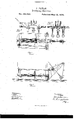
- Figure l is a plan, and Fig. 2 a side view, of a dredgingmachine in the construction of which my improvements are embodied.
- Figs. 3 and 4 are details.
- A is thedipper-crane, constructed and mounted on the dredge in the usual manner, and provided with a dipper or spoon, B.
- the crane and dipper are arranged to operate in the usual manner; but the means by which they are operated are novel.
- 0 O G are hydraulic cylinders, connected to a suitable pump, or othersource of supply, by a pipe, D, which cylinders are provided with valves, by means of which water may be admitted to or allowed to flow from the cylinders, as required in the working of the mechanism.
- These cylinders are provided with pistons and piston-rods, to the ends of which are connected cables, said cables, from the movement imparted to them by the piston-rods, operating the crane and dipperin the following manner:
- the central cylinder, 0, is the dipper or spoon cylinder. From the end of the piston-rod E of this cylinder a connection is made over suitable friction-rollcrs to the dipper by a wire or chain cable, F.
- This cylinder is provided with an inlet-valve, G, and an outlet-valve, G, by the proper manipulationsof which the piston is moved in either direction required, and the dipper elevated or lowered accordingly.
- the admission of water forces the piston in the direction of the arrow, thus elevating the dipper, while the opening of the outlet-valve G permits the water to discharge from the cylinder, thus allowing the dipper to be lowered by the force of its own weight.
- the piston-rod is provided with a roller, 0, which supports the weight of the rod when extended, and prevents sagging.
- the area of the piston is governed, of course, by the weight to be lifted and the pressure of water that can .be applied, and the cable-connection between the piston-rod and dipper may also be varied by means of sheave-blocks to move the dipper faster or slower than the movement of the piston. As shown in the drawings, a movement of one foot would cause the dipper to rise two feet. This proportion under some circum' stances mightnot be satisfactory. Therefore I do not limit myclaim to the arrangement illustrated, as I propose to vary the proportion of parts as circumstances may direct.
- O O are the cylinders which operate the turn-table H of the crane.
- the piston-rods of these cylinders are connected by a continuous cable, I, which cable passes over suitablyar ranged friction-rollers and around the turntable, in the manner shown.
- the operation of each of these cylinders is governed by a threeway cock, J, or other equivalent device, placed on the water-pipe.
- a threeway cock, J, or other equivalent device placed on the water-pipe.
- water is turned on the cylinder at the side to which movement is desired, while the cock of the cylinder at the other side is moved so that the'discharge-port will be open.
- one cylinder will be fill ing and exerting a pull on the crane while the other cylinder is discharging.
- a retrograde movement of the crane is accomplished by re versing the position or the cooks.
- ⁇ Vhat I claim as my invention is- In a dredgingmachine having the crane A and dipper B, the combination of the cylinders 0 0 each provided with avalve, J, operating as described, whereby, as fluid is admitted to one cylinder it is allowed to escape from the other cylinder, the continuous cable I, secured to the piston-rods of said cylinders, and working over the turn-table H. to swing the crane, the cylinder 0, having the valves G G, and the sheaved chain F, attached to its piston-rod and working over the outer sheave of the crane to raise the dipper, all arranged with relation to each other substantially as specified.
Landscapes
- Engineering & Computer Science (AREA)
- Mechanical Engineering (AREA)
- Mining & Mineral Resources (AREA)
- Civil Engineering (AREA)
- General Engineering & Computer Science (AREA)
- Structural Engineering (AREA)
- Earth Drilling (AREA)
Description
J. OANAN. Dredging-Machine.
No. 215,263. Patented May 13, 1879.
N. PETERS, FNOTO-LllI-IOGRAPNER, WASHINGTON. D. C.
JAMES GANAN, or ALLANBURG, ONTARIO, CANADA.
UNITED STATES PATENT OFFrcE.
IMPROVEMENT IN DREDGlNG-MACHINES.
Specification forming part of Letters Iatent No. 215,263, dated May 13, 1879; application filed February 21, 1879.
To all whom it may concern:
Be it known that I, JAMES GANAN, of the village of Allanburg, in the county of Welland and Province of Ontario, Canada, 0011- tractor, have invented certain new and useful Improvements on Dredging-Machines, which improvements are fully set forth and described in the following specification and accompany: ing drawings.
My invention has relation more particularly to improvements in that class of dredging-ma chines known as spoon or dipper dredges and it consists in the application of hydraulic machinery for the purpose of raising the dipper and swinging the dipper-frame, as more particularly described hereinafter.
' In the accompanying drawings, Figure l is a plan, and Fig. 2 a side view, of a dredgingmachine in the construction of which my improvements are embodied. Figs. 3 and 4 are details.
Ais thedipper-crane, constructed and mounted on the dredge in the usual manner, and provided with a dipper or spoon, B. The crane and dipper are arranged to operate in the usual manner; but the means by which they are operated are novel.
0 O G are hydraulic cylinders, connected to a suitable pump, or othersource of supply, by a pipe, D, which cylinders are provided with valves, by means of which water may be admitted to or allowed to flow from the cylinders, as required in the working of the mechanism. These cylinders are provided with pistons and piston-rods, to the ends of which are connected cables, said cables, from the movement imparted to them by the piston-rods, operating the crane and dipperin the following manner: As shown in the drawings, the central cylinder, 0, is the dipper or spoon cylinder. From the end of the piston-rod E of this cylinder a connection is made over suitable friction-rollcrs to the dipper by a wire or chain cable, F. This cylinder is provided with an inlet-valve, G, and an outlet-valve, G, by the proper manipulationsof which the piston is moved in either direction required, and the dipper elevated or lowered accordingly. The admission of water forces the piston in the direction of the arrow, thus elevating the dipper, while the opening of the outlet-valve G permits the water to discharge from the cylinder, thus allowing the dipper to be lowered by the force of its own weight.
The piston-rod is provided with a roller, 0, which supports the weight of the rod when extended, and prevents sagging. The area of the piston is governed, of course, by the weight to be lifted and the pressure of water that can .be applied, and the cable-connection between the piston-rod and dipper may also be varied by means of sheave-blocks to move the dipper faster or slower than the movement of the piston. As shown in the drawings, a movement of one foot would cause the dipper to rise two feet. This proportion under some circum' stances mightnot be satisfactory. Therefore I do not limit myclaim to the arrangement illustrated, as I propose to vary the proportion of parts as circumstances may direct.
O O are the cylinders which operate the turn-table H of the crane. The piston-rods of these cylinders are connected by a continuous cable, I, which cable passes over suitablyar ranged friction-rollers and around the turntable, in the manner shown. The operation of each of these cylinders is governed by a threeway cock, J, or other equivalent device, placed on the water-pipe. In moving the crane by means of these cylinders, water is turned on the cylinder at the side to which movement is desired, while the cock of the cylinder at the other side is moved so that the'discharge-port will be open. Thus one cylinder will be fill ing and exerting a pull on the crane while the other cylinder is discharging. A retrograde movement of the crane is accomplished by re versing the position or the cooks.
That the position and arrangement of the cylinders could be varied from that shown I am aware. Therefore I do not limit my claim to any particular arrangement of parts.
The advantages of my invention are that most of the expensive and intricate mechanism now in use for operating steam dredging-ma chines is dispensed with, and simple, power= ful, and cheap hydraulic machinery substituted therefor. A further advantage is that the liability of breakage is much reduced, and the cost for repairs will be placed at a minimum figure.
I do not claim, broadly, the application of hydraulic machinery for operating cranes and excavator-shovels, and am also aware of En lish Patent No. 11,319 of 1846; but
\Vhat I claim as my invention is- In a dredgingmachine having the crane A and dipper B, the combination of the cylinders 0 0 each provided with avalve, J, operating as described, whereby, as fluid is admitted to one cylinder it is allowed to escape from the other cylinder, the continuous cable I, secured to the piston-rods of said cylinders, and working over the turn-table H. to swing the crane, the cylinder 0, having the valves G G, and the sheaved chain F, attached to its piston-rod and working over the outer sheave of the crane to raise the dipper, all arranged with relation to each other substantially as specified.
JAMES GANAN.
Witnesses:
GEO. A. AIRD, JOHN G. RIDOUT.
Publications (1)
| Publication Number | Publication Date |
|---|---|
| US215263A true US215263A (en) | 1879-05-13 |
Family
ID=2284666
Family Applications (1)
| Application Number | Title | Priority Date | Filing Date |
|---|---|---|---|
| US215263D Expired - Lifetime US215263A (en) | Improvement in dredging-maghines |
Country Status (1)
| Country | Link |
|---|---|
| US (1) | US215263A (en) |
-
0
- US US215263D patent/US215263A/en not_active Expired - Lifetime
Similar Documents
| Publication | Publication Date | Title |
|---|---|---|
| US215263A (en) | Improvement in dredging-maghines | |
| US247829A (en) | And ge | |
| US856759A (en) | Hydraulic elevator. | |
| US388910A (en) | Excavator | |
| US45484A (en) | Improvement in chain-pumps | |
| US909280A (en) | Hydraulic motor for wagon-dumps. | |
| US1051601A (en) | Hydraulic motor. | |
| US198957A (en) | Improvement in dredging-buckets | |
| US56387A (en) | Improvement in pumps | |
| US118151A (en) | Improvement in propelling mechanisms for vessels | |
| US620392A (en) | Force-pump | |
| US665807A (en) | Balance-pump. | |
| US463194A (en) | Ezra w | |
| US187711A (en) | Improvement in hydraulic elevators | |
| US244718A (en) | Thomas dill | |
| US511726A (en) | Elevator | |
| US565815A (en) | Means for pumping oil-wells | |
| US502950A (en) | Hydraulic pump | |
| US579799A (en) | Windlass water-elevator | |
| US781738A (en) | Excavating-machine. | |
| US1021861A (en) | Pumping apparatus. | |
| US829346A (en) | Pumping apparatus. | |
| US200923A (en) | Improvement in lift and force pumps | |
| US133256A (en) | Improvement in hydraulic hoisting apparatus | |
| US298680A (en) | Lingtow |