US2150596A - Manufacture of cigarettes - Google Patents
Manufacture of cigarettes Download PDFInfo
- Publication number
- US2150596A US2150596A US97707A US9770736A US2150596A US 2150596 A US2150596 A US 2150596A US 97707 A US97707 A US 97707A US 9770736 A US9770736 A US 9770736A US 2150596 A US2150596 A US 2150596A
- Authority
- US
- United States
- Prior art keywords
- stubs
- stub
- drum
- conveyor
- longitudinal axes
- Prior art date
- Legal status (The legal status is an assumption and is not a legal conclusion. Google has not performed a legal analysis and makes no representation as to the accuracy of the status listed.)
- Expired - Lifetime
Links
- 235000019504 cigarettes Nutrition 0.000 title description 29
- 238000004519 manufacturing process Methods 0.000 title description 19
- 239000000463 material Substances 0.000 description 12
- 230000000694 effects Effects 0.000 description 5
- 241000208125 Nicotiana Species 0.000 description 4
- 235000002637 Nicotiana tabacum Nutrition 0.000 description 4
- 238000006073 displacement reaction Methods 0.000 description 3
- 230000002093 peripheral effect Effects 0.000 description 2
- 238000000926 separation method Methods 0.000 description 2
- 239000002131 composite material Substances 0.000 description 1
- 238000001914 filtration Methods 0.000 description 1
- 238000000034 method Methods 0.000 description 1
Images


Classifications
-
- A—HUMAN NECESSITIES
- A24—TOBACCO; CIGARS; CIGARETTES; SIMULATED SMOKING DEVICES; SMOKERS' REQUISITES
- A24C—MACHINES FOR MAKING CIGARS OR CIGARETTES
- A24C5/00—Making cigarettes; Making tipping materials for, or attaching filters or mouthpieces to, cigars or cigarettes
- A24C5/47—Attaching filters or mouthpieces to cigars or cigarettes, e.g. inserting filters into cigarettes or their mouthpieces
- A24C5/478—Transport means for filter- or cigarette-rods in view of their assembling
Definitions
- This invention is for improvements in or relating to the manufacture of cigarettes, and refers more particularly to a method of and a machine for making cigarettes, provided with filter plugs,
- a 'I'he mouthpieces shall for convenience be referred to herein as stubs, and the term stub shall include mouthpieces in the form of tubes of paper or other material which may be empty, l0 or filled entirely, or partly with filtering or avouring material or tobacco. It will be appreciated that where the tubes are not lled they should have suiiicient rigidity to enable them to remain open when the cigarettes are being smoked.
- stub shall also be deemed to include a composite mouthpiece constituted 'in part by a length of wrapped cigarette rod, and in part by a'length of filter or avouring material 20 wrapped in a tubular wrapper or by a tubular piece which is either hollow or partly filled with filter or iiavouringy material.
- the term stub shall also be deemed to include a mouthpiece comprising a length of tobacco iiller in a wrapper, 25 which tobacco is of a dinerent kind of tobacco from that forming the main body of the cigarette.
- Cigarettes provided with stubs will, for convenience, be referred, to herein as -mouthpiece cigarettes.
- the stubs are not uniform in shape, and they may, for example, be oval in shape, in which case it is often found during the feeding of the stubs that when the stubs are considered in a. single plane, the major axis of one stub is at right angles to the major axis of the adjacent stub. When this occurs, difliculty isI invariably experienced in satisfactorily feeding the stubs.
- Diiculty is also experienced when the stubs are formed from paper or other iilter material, ⁇ such for example as layers of crepe paper between which there are placed layers of cellulosic ma.- terial. It is found, when the stubs are formed from such material, that frequently a portion of material projects from the end ⁇ of a stub, and that when the stubs are abutting, the projecting portions from one stub become entangled with the end of the adjacent stub.- This dilculty 'is more particularly noticeable when the stubs are u fed from a hopper in the form of comparatively (Cl. ISI-39) long lengths of stub material which are severed into desired lengths for uniting with cigarettes.
- apparatus comprising meansv for feeding a plurality of axially aligned stubs which l0 have ends abutting or closely adjacent, and means operative to space said stubs apart from each other in the direction of their longitudinal axes.
- 'I'he spacing of the stubs may be 'repeated or eifected in a plurality of stages, and between the repeated spacing or stages means may be provided to align the stubs with respect to the path which they followed before the separating operation and the means may be operative to move the stubs in the direction of their longitudinal axes and towards the central point of their combined overall length.
- the stubs may be fed by a conveyor, and a guide element or elements provided to engage with the stubs to space the stubs apart from each other in the direction of the longitudinal axes.
- the conveyor may comprise a rotatable drum having utes in its periphery for the reception of the stubs and aguide may be provided for each stub, the guide extending around or partly around the periphery of the drum.
- the guides are disposed at varying distances from the periphery of the drum, whereby the end faces of the stubs in those flutes which are controlled by.
- Stubs of comparatively long length may be delivered from a hopper to the feeding means, and cutting elements provided to subdivide the long lengths, whilst they are carried by said means.
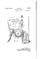
- Figure 1 is a vertical sectional view of stub feeding mechanism constructed in accordance 50 with the invention.
- Figure 2 is a ,side'elevation partly in section and drawn to an enlarged scale, showing a portion of the'stub feeding mechanism illustrated in Figure 1.
- Figure 3 is a view of Figure 2, looking in the direction of the arrow A.
- Figure 4 is a side elevation of the mechanism illustrating gearing for driving the various rotating parts.
- Figure 6 is a sectional view on the line 6-6 of Figure 2.
- a hopper I from which the lengths of material are deposited one at a time into the flutes 2 of a rotatable drum 3.
- the stubs are supported in the hopper by a fixed plate and an oscillating plate IOI.
- is pivoted at
- 04 is carried by one arm on a bell crank lever which is pivoted at.
- Thecam follower is maintained against the cam
- the action of the plate IOI is to vibrate the stubs in the hopper I in-order to facilitate the feeding of the stubs through the space
- the drum 3 is divided' to enable knives 4 to sever the comparatively long stubs, as seen clearly in Figure 3, into three stubs of double the length required in the finished cigarettes.
- the knives 4 are circular rotating knives carried by arms 5; adjustably mounted on a spindle I5. The knives are rotated in any suitable manner from the main drive of the machine, and grinders 'I are provided to sharpen both sides of the knives.
- Guides 8 and 9 are provided to retain the stubs in the flutes 2 of the conveyor, that is the drum 3, and the guides are so arranged that -they are disposed at varying distances frm the periphery of ,the drum. It will be seen from Figure 2 that the guide 9- is closer to the periphery of the drum 3 than is the guide 8. The guide 9 is positioned to engage the middle severed stub, as can be seen from Figure 3, and as the drum 3 rotates, the outer stubs fall partly out of the flutes 2 and are engaged by the guide 8.
- the end faces of the outer stubs are engaged by the guide 9, the edges 59 of which are formedras cam faces, and as the drum 3 continues to move the stubs past the cam faces and the guide 9, the outer stubs are moved away from the central stub so that the three stubs are spaced apart from each other in the direction of their longitudinal axes. This permits the stubs to fall quite independentlyof one another and facilitates the transfer from the utes 2 to the next conveyor as described below.
- the stubs which have been spaced apart are deposited into the flutes I0 of a rotatable wheel II and in order to ensure that' each stub is placed into the flutes I0, fork members I2 project through slots in the drum 3 and engage with and ensure that three aligned stubs are removed from a flute 2 of the drum 3 and deposited into a ute I0 of the drum I I which in turn delivers the stubs to the flutes I5 of a rotatable drum I6.
- the stubs when being spaced times a portion of material projecting from an end of a stub, the projecting portion being entangled with the end of the adjacent stub.
- the stubs when being spaced apart in the direction of their longitudinal axes, are sometimes caused to be moved out of alignment with respect to the path through which they are intended to be carried by the drum 3, and in such cases it is necessary to re-align the stubs with the path through which the drum 3 is arranged to carry them, otherwise When they are placed upon a conveyor which moves the stubs into alignment with cigarette lengths, it is found that the stubs are not correctly deposited on the conveyor.
- the stubs in the flutes I5 are moved in the direction of their longitudinal axes andtowards the central point of their combined overall length, the central point beingconsidered when the stubs are correctly aligned with respect to the path through which the drum 3 is arranged to carry the stubs.
- the means to effect this operation comprises a pair of guides I3 and I4 which are bell-mouthed where the stubs rst engage with the guides.
- the guide I8 is provided with edges 58 ⁇ formed as cam faces as above described with respect to the guide 9, and the inner end faces of the outer stubs which stubs are controlled'by the guides I'I and I9 respectively are engaged by the cam faces of the guide I8, th'e outer stubs being thereby moved in the direction of their longitudinal axes so' that the stubs are spaced apart.
- This second separation serves to facilitate the fall of the stubs from the drum as in the previous case, and also more accurately locates the stubs and spaces them apart axially.
- the separation of the stubs may be effected in a plurality of stages by suitably modifying the shape of the cams 9 and I8.
- the stubs are delivered from the drum I6 to control means formed as stub arresting surfaces. As the stubs leave the flutes I5 they roll over inclined surfaces 2
- the stub arresting surfaces 20 comprise three movable members, one for each of the three stubs, delivered by a flute I5, and the surfaces are arranged above the path of an endless conveyor 23 formed in the present case as a rotatable disc and provided with pusher pieces 24, each of which engages with a stub to move the stub above a trough 25 in which the stub is deposited and inserted into the space between successive cigarette lengths which are to be assembled with the stub in order to form mouthpiece cigarettes.
- An annular space 26 is provided between the conveyor 23 and an outer wall 21, the stubs being Vmoved through this space by the pusher pieces 24.
- the outer wall 21 is carried on a stationary supporting plate 28.
- the supporting plate 28 forms a bottom to the space 26 between the conveyor 23 and the wall 21, except at a place directly above the trough 25, a space being provided in the plate 28 at this point to enable the stubs to be deposited into the trough 25.
- the speed of the conveyor 23 is such that whilst one flute I is passing oifer the space 26, three pusher pieces 24 will move past the place at which the three stubs delivered by the flute are arrested by the surfaces 20.
- the conveyor 23 and' drum I 6 may be driven in any convenient manner.
- the sprocket a shown in Figures 1 and 4 is driven by gearing from the main shaft of the machine which drives the spindle on which sprocket a is mounted.
- Sprocket a is connected by a chain with a sprocket b to which a gear c is fixed, the gear c intermeshing with a gear d mounted on the spindle e.
- gear f To the near end of the spindle e is secured a gear f, Figure 4; the gear f intermeshes with a gear g to which is secured a smaller gear h which in turn intermeshes with a large gear 9 carried on the spindle 1c on which the drum 3 is mounted.
- a smaller gear m is mounted on a shaft n and intermeshes with the large gear y', and another gear p is also mounted on the spindle n and intermeshes with a gear q mounted on the spindle r of the fiuted drum I6.
- a gear s is mounted on the spindle t of the uted drum II and intermeshes with the gear q.
- 'I'he conveyor 23 is also driven from the shaft which carries the sprocket a, and is driven by intermeshing gears u and v, the gear v being mounted on the same shaft as the sprocket a.
- the gearing above described is so arranged that three pusher pieces 24 pass the delivery point while the drums 3, I I, and I6 each move a distance of one flute.
- each of the stubs In order to allow each of the stubs to be fed in turn on to the supporting plate 28, 'eachof the arresting surfaces is withdrawn in turn.
- the arresting surfaces are moved into and out of the path of the stubs by means of levers 29 which are operated by cams 38, a spring 3
- stub engaging elements 32 each of which is arranged to engage with one of the stubs delivered by one of the flutes I5.
- the stub engaging elements are pivoted at 33, and are operated in timed relationship with the stub arresting surfaces 2li.
- ⁇ stub engaging elements 32 are provided with tailpieces 34, which protrude through slots in the arresting surfaces 20, and the tail pieces are engaged by stops 35 secured to the arresting surfaces.
- each of the stops 35 engages with the corresponding tail piece 34, and causes the respective stub engaging element 32 to be pivoted about the point 33 so that it kmoves downwardly and engages with the stub upon the supporting plate 28, and ensures that the stub is positioned onthe supporting plate before the stub is engaged by a pusher piece 24.
- the stub engaging element 32 ensures that the stub is in position on the supporting plate 28, and that it does not rebound after falling on to the plate, thereby tending to assume an undesired position.
- the central stub is the first to be deposited upon the plate 28, whereafter the two outer ones are deposited one after the other.
- a conveyor for a plurality of substantially axially aligned stubs, two or more of said stubs being in abutting relation to each other, ,and means to engage an end face of a stub on the conveyor and tomove the stub in the direction of its longitudinal axis and space it apart from an adjacent abutting stub on the conveyor.
- a conveyor for a plurality of axially aligned stubs means to effect displacement of the stubs in a direction transverse to the longitudinal axes thereof, and means to engage an end face of a displaced stub and to move that stub in the direction of its longitudinal axis to space it lapart from contacting relation with an adjacent stub.
- a conveyor to move a plurality of axially aligned stubs in a direction transverse to their longitudinal axes, and means to alter the relative positions of the stubs on the conveyor to space the stubsapart in the direction of their longitudinal axes.
- a conveyor to move a plurality of substantially axially aligned stubs in a direction transverse to their longitudinal axes, and means to engage an end face of a stub on the conveyor and to move the stub in the direction of its longitudinal axis and space it apart from an adjacentstub on the conveyor.
- a conveyor to move a plurality of axially aligned stubs in a direction transverse to their longitudinal axes, means to eiect displacement of the stubs in a direction transverse to the longitudinal axes thereof, and means to engage an end face of a displaced stub and to move that stub in the direction of its longitudinal axis to space it apart from contact with an adjacent stub.
- a conveyor to move a plurality of substantially axially aligned stubs in a direction transverse to their longitudinal axes, means to effect spacing of the stubs in the direction of their longitudinal axes in a plurality of stages, and means operative between successive stages to move the stubs in the direction ⁇ of their longitudinal axes and toward the central point of their combined over-all length, said first named means comprising elements to engage an end face of a stub and move the stub in the direction of its longitudinal axis.
- a conveyor to move a plurality of substantially axially aligned stubs in a direction transverse to their longitudinal axes, means to eiect spacing of the stubs in the direction -of their longitudinal'axes in a plurality of stages, and means operative between successive stages to move the stubs in the direction of their longitudinal axes and toward the central point of their combined over-al1 length, said rst named means comprising a device to effect. displacement of the stubs in a direction transverse to the longitudinal axes thereof, and elements to engage an end face of a stub and move the stub in the direction of its longitudinal axis.
- a conveyor to' move a plurality of substantially axially aligned stubs in a direction transverse to their longitudinal axes, means toJ effect spacing of the stubs in the direction of their longitudinal axes in a plurality of stages, elements to engage an end face of a stub and move the stubin the direction of its longitudinal axis, and means operative between successive stages to engage the end face of the stub oppo.
- a rotatable drum having peripheral utes extending in a direction substantially parallel to the axis of rotation of the drum, a ute being arranged to contain a plurality of substantially axially aligned stubs, and means to alter the relative positions of the stubs in a flute to space the stubs apart in the direction of their longitudinal axes.
- a rotatable drum having peripheral flutes extending in a direction substantially parallel to the axis of rotation of the drum, a flute being arranged to contain a plurality of substantially axially aligned stubs, a guide for each stub contained in a iiute, said guides being so arranged that alternate stubs are displaced in a direction transverse to the longitudinal axes of the stubs, the edges of the guides controlling the remaining stubs, being arranged to engage an end face of a displaced stub and so shaped as to move the displaced stubs in the direction of their longitudinal axes.
Landscapes
- Manufacturing Of Cigar And Cigarette Tobacco (AREA)
Description
March 14, 1939. A. BINGHAM 2,150,596
MANUFACTURE OF CIGARETTES Filed Aug. 24, 19.36 4 sheets-sheet 1 March 14, 1939, A. BINGHAM 2,150,596
MANUFACTURE oF GIGARETTES Filed Aug. 24,l 1956 4 sheets-sheet 2 www Il,
lll/lll,"
March 14, 1939. A. BINGHAM MANUFACTURE OF CI'GARETTES 4 Sheets-Sheet 5 Filed Aug. 24, 1936 INVENTORS I @4d/EI'. @hwy March 14, 1939. A, B|NGHAM 2,150,596
v MANUFACTURE oF GIGARETTES Y' l Filed Aug.. 24, 1936 4 Sheets-Sheet 4 Patented Mar. 14, 1939 MANUFACTURE F CIGABETTES Arthur Bingham, Deptford, London, England, assignor to Molins Machine Company, Limited,
London, England Application August 24, 1936,seria1 No. 97,701 In Great Britain October 4, 1935 11 Claims.
This invention is for improvements in or relating to the manufacture of cigarettes, and refers more particularly to a method of and a machine for making cigarettes, provided with filter plugs,
mouthpieces or the like.
A 'I'he mouthpieces shall for convenience be referred to herein as stubs, and the term stub shall include mouthpieces in the form of tubes of paper or other material which may be empty, l0 or filled entirely, or partly with filtering or avouring material or tobacco. It will be appreciated that where the tubes are not lled they should have suiiicient rigidity to enable them to remain open when the cigarettes are being smoked.
The term stub shall also be deemed to include a composite mouthpiece constituted 'in part by a length of wrapped cigarette rod, and in part by a'length of filter or avouring material 20 wrapped in a tubular wrapper or by a tubular piece which is either hollow or partly filled with filter or iiavouringy material. The term stub shall also be deemed to include a mouthpiece comprising a length of tobacco iiller in a wrapper, 25 which tobacco is of a dinerent kind of tobacco from that forming the main body of the cigarette.
Cigarettes provided with stubs will, for convenience, be referred, to herein as -mouthpiece cigarettes.
It is found when a plurality of stubs is fed in a manner such that the stubs are in axial alignment and abutting end to end, that when it is desired to separate the stubs, the stubs tend to adhere to each other, due to a number of causes. v Sometimes the stubs are not uniform in shape, and they may, for example, be oval in shape, in which case it is often found during the feeding of the stubs that when the stubs are considered in a. single plane, the major axis of one stub is at right angles to the major axis of the adjacent stub. When this occurs, difliculty isI invariably experienced in satisfactorily feeding the stubs.
Diiculty is also experienced when the stubs are formed from paper or other iilter material,` such for example as layers of crepe paper between which there are placed layers of cellulosic ma.- terial. It is found, when the stubs are formed from such material, that frequently a portion of material projects from the end `of a stub, and that when the stubs are abutting, the projecting portions from one stub become entangled with the end of the adjacent stub.- This dilculty 'is more particularly noticeable when the stubs are u fed from a hopper in the form of comparatively (Cl. ISI-39) long lengths of stub material which are severed into desired lengths for uniting with cigarettes.
According to the present invention there is provided in or for a machine for manufacturing mouthpiece cigarettes by uniting aligned adja.- 5 cent stubs and cigarettes by securing wrapping material to or around said adjacent stubs and cigarettes whilst said stubs and cigarettes are moving axially, apparatus comprising meansv for feeding a plurality of axially aligned stubs which l0 have ends abutting or closely adjacent, and means operative to space said stubs apart from each other in the direction of their longitudinal axes. 'I'he spacing of the stubs may be 'repeated or eifected in a plurality of stages, and between the repeated spacing or stages means may be provided to align the stubs with respect to the path which they followed before the separating operation and the means may be operative to move the stubs in the direction of their longitudinal axes and towards the central point of their combined overall length.
The stubs may be fed by a conveyor, and a guide element or elements provided to engage with the stubs to space the stubs apart from each other in the direction of the longitudinal axes. The conveyor may comprise a rotatable drum having utes in its periphery for the reception of the stubs and aguide may be provided for each stub, the guide extending around or partly around the periphery of the drum. y The guides are disposed at varying distances from the periphery of the drum, whereby the end faces of the stubs in those flutes which are controlled by. the guides disposed at the greatest distance from the periphery of the drum are engaged by a remaining guide or guides, a part at least of said remaining guide or guides being disposed in the path of the stubs' engaged thereby, so that the stubs so engaged are spaced apart from, each 40 other in the direction oi' their longitudinal axes. Stubs of comparatively long length may be delivered from a hopper to the feeding means, and cutting elements provided to subdivide the long lengths, whilst they are carried by said means.
The invention will be more particularly de scribed with reference to the accompanying drawings, in which:-
Figure 1 is a vertical sectional view of stub feeding mechanism constructed in accordance 50 with the invention. l
Figure 2 is a ,side'elevation partly in section and drawn to an enlarged scale, showing a portion of the'stub feeding mechanism illustrated in Figure 1.
Figure 3 is a view of Figure 2, looking in the direction of the arrow A.
Figure 4 is a side elevation of the mechanism illustrating gearing for driving the various rotating parts.
Figure 6 is a sectional view on the line 6-6 of Figure 2.
Like references refer to like parts throughout the various figures of the drawings.
Referring to the drawings, comparatively long lengths of stub material are contained in a hopper I, from which the lengths of material are deposited one at a time into the flutes 2 of a rotatable drum 3. The stubs are supported in the hopper by a fixed plate and an oscillating plate IOI. The plate |0| is pivoted at |02, and is oscillated by a cam |03. A cam follower |04 is carried by one arm on a bell crank lever which is pivoted at. |06 to the frame of the machine. Thecam follower is maintained against the cam |03 by a spring, not shown. To the other arm of the bell crank lever |05 there is connected a link |01 which link is also connected to the plate IOI. The action of the plate IOI is to vibrate the stubs in the hopper I in-order to facilitate the feeding of the stubs through the space |08 formed between the end of the plate IOI and' the surface of the stationary support |00. It is found that if such a plate as IOI is not used there is sometimes a tendency for the stubs to become jammed in the hopper, and not freely to pass through the opening |08. The drum 3 is divided' to enable knives 4 to sever the comparatively long stubs, as seen clearly in Figure 3, into three stubs of double the length required in the finished cigarettes. The knives 4 are circular rotating knives carried by arms 5; adjustably mounted on a spindle I5. The knives are rotated in any suitable manner from the main drive of the machine, and grinders 'I are provided to sharpen both sides of the knives.
The stubs which have been spaced apart are deposited into the flutes I0 of a rotatable wheel II and in order to ensure that' each stub is placed into the flutes I0, fork members I2 project through slots in the drum 3 and engage with and ensure that three aligned stubs are removed from a flute 2 of the drum 3 and deposited into a ute I0 of the drum I I which in turn delivers the stubs to the flutes I5 of a rotatable drum I6.
It is found that whenthe stubs are being spaced times a portion of material projecting from an end of a stub, the projecting portion being entangled with the end of the adjacent stub. When such is the case, the stubs, when being spaced apart in the direction of their longitudinal axes, are sometimes caused to be moved out of alignment with respect to the path through which they are intended to be carried by the drum 3, and in such cases it is necessary to re-align the stubs with the path through which the drum 3 is arranged to carry them, otherwise When they are placed upon a conveyor which moves the stubs into alignment with cigarette lengths, it is found that the stubs are not correctly deposited on the conveyor. In order to avoid this difficulty, the stubs in the flutes I5 are moved in the direction of their longitudinal axes andtowards the central point of their combined overall length, the central point beingconsidered when the stubs are correctly aligned with respect to the path through which the drum 3 is arranged to carry the stubs. The means to effect this operation comprises a pair of guides I3 and I4 which are bell-mouthed where the stubs rst engage with the guides. and the guides I3 and I4 gradually converge towards each other until they are in alignment with the drum 3, and are spaced apart in a manner such that the stubs are completely closed together so that they abut end to end and are again conveyed in the same general path as that through which the drum 3 previously conveyed the stubs. v
After the stubs being conveyed by the drum I5 have been closed together they are again spaced apart in the direction of their longitudinal axes whilst' being controlled by guides I'I, I8 and I9, the guides I'I and I9 being disposed at a distance from the periphery of the drum I6 which is greater than the distance between the peripheryof the drum and the guide In. The guide I8 is provided with edges 58` formed as cam faces as above described with respect to the guide 9, and the inner end faces of the outer stubs which stubs are controlled'by the guides I'I and I9 respectively are engaged by the cam faces of the guide I8, th'e outer stubs being thereby moved in the direction of their longitudinal axes so' that the stubs are spaced apart. This second separation serves to facilitate the fall of the stubs from the drum as in the previous case, and also more accurately locates the stubs and spaces them apart axially.
It will be appreciated that if desired the separation of the stubs may be effected in a plurality of stages by suitably modifying the shape of the cams 9 and I8.
The stubs are delivered from the drum I6 to control means formed as stub arresting surfaces. As the stubs leave the flutes I5 they roll over inclined surfaces 2| and 22, the surface 22, which engages with the central stub, being arranged slightly in advance of the surfaces 2| over which the outer stubs pass, the arrangement being clearly shown in Figure 2 and such' as to obtain the free delivery of the stubs from the flutes to the controlling means.
The stub arresting surfaces 20 comprise three movable members, one for each of the three stubs, delivered by a flute I5, and the surfaces are arranged above the path of an endless conveyor 23 formed in the present case as a rotatable disc and provided with pusher pieces 24, each of which engages with a stub to move the stub above a trough 25 in which the stub is deposited and inserted into the space between successive cigarette lengths which are to be assembled with the stub in order to form mouthpiece cigarettes.
An annular space 26 is provided between the conveyor 23 and an outer wall 21, the stubs being Vmoved through this space by the pusher pieces 24. The outer wall 21 is carried on a stationary supporting plate 28. The supporting plate 28 forms a bottom to the space 26 between the conveyor 23 and the wall 21, except at a place directly above the trough 25, a space being provided in the plate 28 at this point to enable the stubs to be deposited into the trough 25. The speed of the conveyor 23 is such that whilst one flute I is passing oifer the space 26, three pusher pieces 24 will move past the place at which the three stubs delivered by the flute are arrested by the surfaces 20.
The conveyor 23 and' drum I 6 may be driven in any convenient manner. For example, the sprocket a shown in Figures 1 and 4 is driven by gearing from the main shaft of the machine which drives the spindle on which sprocket a is mounted. Sprocket a is connected by a chain with a sprocket b to which a gear c is fixed, the gear c intermeshing with a gear d mounted on the spindle e. To the near end of the spindle e is secured a gear f,Figure 4; the gear f intermeshes with a gear g to which is secured a smaller gear h which in turn intermeshes with a large gear 9 carried on the spindle 1c on which the drum 3 is mounted.
A smaller gear m is mounted on a shaft n and intermeshes with the large gear y', and another gear p is also mounted on the spindle n and intermeshes with a gear q mounted on the spindle r of the fiuted drum I6. A gear s is mounted on the spindle t of the uted drum II and intermeshes with the gear q.
'I'he conveyor 23 is also driven from the shaft which carries the sprocket a, and is driven by intermeshing gears u and v, the gear v being mounted on the same shaft as the sprocket a. The gearing above described is so arranged that three pusher pieces 24 pass the delivery point while the drums 3, I I, and I6 each move a distance of one flute.
In order to allow each of the stubs to be fed in turn on to the supporting plate 28, 'eachof the arresting surfaces is withdrawn in turn. The arresting surfaces are moved into and out of the path of the stubs by means of levers 29 which are operated by cams 38, a spring 3| being provided to maintain the parts in their working position.
Above the stubs supported by the stub arresting surfaces 20, there are provided three stub engaging elements 32, each of which is arranged to engage with one of the stubs delivered by one of the flutes I5. The stub engaging elements are pivoted at 33, and are operated in timed relationship with the stub arresting surfaces 2li. The
` stub engaging elements 32 are provided with tailpieces 34, which protrude through slots in the arresting surfaces 20, and the tail pieces are engaged by stops 35 secured to the arresting surfaces. As the lobes 5I of the cams 30 cause the arresting surfaces 28 to bev withdrawn out of the path of the stubs so as to allow them to be deposited upon the supporting plate 28, each of the stops 35 engages with the corresponding tail piece 34, and causes the respective stub engaging element 32 to be pivoted about the point 33 so that it kmoves downwardly and engages with the stub upon the supporting plate 28, and ensures that the stub is positioned onthe supporting plate before the stub is engaged by a pusher piece 24. The stub engaging element 32 ensures that the stub is in position on the supporting plate 28, and that it does not rebound after falling on to the plate, thereby tending to assume an undesired position.
When three stubs are positioned above the space 26, they are allowed to fall at predetermined intervals so that they are engaged in succession by one of the pusher pieces 24, and in the example shown in the drawings, the central stub is the first to be deposited upon the plate 28, whereafter the two outer ones are deposited one after the other.
What I claim as my invention and desire to secure by Letters Patent isz- 1. In a machine for manufacturing mouthpiece cigarettes, a conveyor for a pluralityvof axially aligned stubs, two or more of said stubs being in abutting relation to each other, and means to alter the relative positions of the abutting stubs on the conveyor to space'the stubs apart in the direction of their longitudinal axes.
2. In a machine for manufacturing mouthpiece cigarettes, a conveyor for a plurality of substantially axially aligned stubs, two or more of said stubs being in abutting relation to each other, ,and means to engage an end face of a stub on the conveyor and tomove the stub in the direction of its longitudinal axis and space it apart from an adjacent abutting stub on the conveyor.
3. In a machine for manufacturing mouthpiece cigarettes, a conveyor for a plurality of axially aligned stubs, means to effect displacement of the stubs in a direction transverse to the longitudinal axes thereof, and means to engage an end face of a displaced stub and to move that stub in the direction of its longitudinal axis to space it lapart from contacting relation with an adjacent stub.
5. In a machine for manufacturing mouthpiece cigarettes, a conveyor to move a plurality of substantially axially aligned stubs in a direction transverse to their longitudinal axes, and means to engage an end face of a stub on the conveyor and to move the stub in the direction of its longitudinal axis and space it apart from an adjacentstub on the conveyor.
6. In a machine for manufacturing mouthpiece cigarettes, a conveyor to move a plurality of axially aligned stubs in a direction transverse to their longitudinal axes, means to eiect displacement of the stubs in a direction transverse to the longitudinal axes thereof, and means to engage an end face of a displaced stub and to move that stub in the direction of its longitudinal axis to space it apart from contact with an adjacent stub.
7. In a machine for manufacturing mouthpiece cigarettes, a conveyor to move a plurality of substantially axially aligned stubs in a direction transverse to their longitudinal axes, means to effect spacing of the stubs in the direction of their longitudinal axes in a plurality of stages, and means operative between successive stages to move the stubs in the direction `of their longitudinal axes and toward the central point of their combined over-all length, said first named means comprising elements to engage an end face of a stub and move the stub in the direction of its longitudinal axis.
8. In a machine for manufacturing mouthpiece cigarettes, a conveyor to move a plurality of substantially axially aligned stubs in a direction transverse to their longitudinal axes, means to eiect spacing of the stubs in the direction -of their longitudinal'axes in a plurality of stages, and means operative between successive stages to move the stubs in the direction of their longitudinal axes and toward the central point of their combined over-al1 length, said rst named means comprising a device to effect. displacement of the stubs in a direction transverse to the longitudinal axes thereof, and elements to engage an end face of a stub and move the stub in the direction of its longitudinal axis.
9. In a machine for manufacturing mouthpiece cigarettes, a conveyor to' move a plurality of substantially axially aligned stubs in a direction transverse to their longitudinal axes, means toJ effect spacing of the stubs in the direction of their longitudinal axes in a plurality of stages, elements to engage an end face of a stub and move the stubin the direction of its longitudinal axis, and means operative between successive stages to engage the end face of the stub oppo.
elements, to move the stubs in the direction of their longitudinal axes and toward the central point of the combined over-all length of the stubs.
10. In a machine for manufacturing mouthpiece cigarettes, a rotatable drum having peripheral utes extending in a direction substantially parallel to the axis of rotation of the drum, a ute being arranged to contain a plurality of substantially axially aligned stubs, and means to alter the relative positions of the stubs in a flute to space the stubs apart in the direction of their longitudinal axes.
11. In a machine for manufacturing mouthpiece cigarettes, a rotatable drum having peripheral flutes extending in a direction substantially parallel to the axis of rotation of the drum, a flute being arranged to contain a plurality of substantially axially aligned stubs, a guide for each stub contained in a iiute, said guides being so arranged that alternate stubs are displaced in a direction transverse to the longitudinal axes of the stubs, the edges of the guides controlling the remaining stubs, being arranged to engage an end face of a displaced stub and so shaped as to move the displaced stubs in the direction of their longitudinal axes.
ARTHUR BINGHAM.
Applications Claiming Priority (1)
| Application Number | Priority Date | Filing Date | Title |
|---|---|---|---|
| GB27416/35A GB463654A (en) | 1935-10-04 | 1935-10-04 | Improvements in or relating to the manufacture of cigarettes |
Publications (1)
| Publication Number | Publication Date |
|---|---|
| US2150596A true US2150596A (en) | 1939-03-14 |
Family
ID=10259214
Family Applications (1)
| Application Number | Title | Priority Date | Filing Date |
|---|---|---|---|
| US97707A Expired - Lifetime US2150596A (en) | 1935-10-04 | 1936-08-24 | Manufacture of cigarettes |
Country Status (3)
| Country | Link |
|---|---|
| US (1) | US2150596A (en) |
| FR (1) | FR811557A (en) |
| GB (1) | GB463654A (en) |
Cited By (4)
| Publication number | Priority date | Publication date | Assignee | Title |
|---|---|---|---|---|
| US2602453A (en) * | 1948-07-02 | 1952-07-08 | Amalgamated Tobacco Corp Ltd | Filter tip feed mechanism for filter tip cigarette-making machines |
| US2652138A (en) * | 1948-12-03 | 1953-09-15 | Molins Machine Co Ltd | Apparatus for feeding rodlike articles |
| US2858046A (en) * | 1954-03-31 | 1958-10-28 | Koerber & Co Kg | Machines for making filter tip cigarettes |
| US2874701A (en) * | 1954-03-31 | 1959-02-24 | Koerber & Co Kg | Guiding system on machines for producing filter tip cigarettes |
-
1935
- 1935-10-04 GB GB27416/35A patent/GB463654A/en not_active Expired
-
1936
- 1936-08-24 US US97707A patent/US2150596A/en not_active Expired - Lifetime
- 1936-10-02 FR FR811557D patent/FR811557A/en not_active Expired
Cited By (4)
| Publication number | Priority date | Publication date | Assignee | Title |
|---|---|---|---|---|
| US2602453A (en) * | 1948-07-02 | 1952-07-08 | Amalgamated Tobacco Corp Ltd | Filter tip feed mechanism for filter tip cigarette-making machines |
| US2652138A (en) * | 1948-12-03 | 1953-09-15 | Molins Machine Co Ltd | Apparatus for feeding rodlike articles |
| US2858046A (en) * | 1954-03-31 | 1958-10-28 | Koerber & Co Kg | Machines for making filter tip cigarettes |
| US2874701A (en) * | 1954-03-31 | 1959-02-24 | Koerber & Co Kg | Guiding system on machines for producing filter tip cigarettes |
Also Published As
| Publication number | Publication date |
|---|---|
| GB463654A (en) | 1937-04-05 |
| FR811557A (en) | 1937-04-17 |
Similar Documents
| Publication | Publication Date | Title |
|---|---|---|
| USRE26900E (en) | Method and apparatus for making and manipulating cigarettes and similar rod-shaped articles | |
| US3131612A (en) | Production of mouthpieces for cigarettes | |
| US2649761A (en) | Manufacture of filter tip and like composite cigarettes | |
| US2952105A (en) | Wrapping device | |
| US2172804A (en) | Manufacture of cigarettes | |
| US3357320A (en) | Multiple filter assembly apparatus | |
| US2166486A (en) | Cigarette apparatus | |
| US2156600A (en) | Manufacture of cigarettes | |
| US2423554A (en) | Method of and means for making mouthpiece cigarettes | |
| US2152416A (en) | Manufacture of cigarettes | |
| US3081778A (en) | Method of making a cigarette having a composite filter plug | |
| US2150596A (en) | Manufacture of cigarettes | |
| US3478632A (en) | Filter-section distributing devices,especially for use in the manufacture of filter tipped cigarettes | |
| US3311008A (en) | Process of severing rod-like articles and arranging the severed articles in a row | |
| US3308833A (en) | Machine for making cigarettes | |
| US3286809A (en) | Method and apparatus for manipulating rod shaped articles | |
| US2118783A (en) | Cigarette | |
| US3367341A (en) | Apparatus for connecting aligned cigarettes and filters | |
| US2929384A (en) | Cigarette making machine | |
| US3119397A (en) | Manufacture of mouthpiece cigarettes | |
| US3238825A (en) | Method of feeding and cutting filters | |
| US2798495A (en) | Manufacture of mouthpiece cigarettes | |
| US2105412A (en) | Manufacture of cigarettes | |
| US2169662A (en) | Manufacture of cigarettes | |
| US3091245A (en) | Means for wrapping connecting leaves around the abutment regions of assemblies compriising cigarettes and filter plugs |