US2148564A - Power transmission gearing assembly - Google Patents
Power transmission gearing assembly Download PDFInfo
- Publication number
- US2148564A US2148564A US194095A US19409538A US2148564A US 2148564 A US2148564 A US 2148564A US 194095 A US194095 A US 194095A US 19409538 A US19409538 A US 19409538A US 2148564 A US2148564 A US 2148564A
- Authority
- US
- United States
- Prior art keywords
- shaft
- gears
- pinion
- drive
- coupling
- Prior art date
- Legal status (The legal status is an assumption and is not a legal conclusion. Google has not performed a legal analysis and makes no representation as to the accuracy of the status listed.)
- Expired - Lifetime
Links
- 230000005540 biological transmission Effects 0.000 title description 22
- 230000008878 coupling Effects 0.000 description 46
- 238000010168 coupling process Methods 0.000 description 46
- 238000005859 coupling reaction Methods 0.000 description 46
- 230000000712 assembly Effects 0.000 description 9
- 238000000429 assembly Methods 0.000 description 9
- 230000033001 locomotion Effects 0.000 description 8
- 238000005452 bending Methods 0.000 description 5
- 238000006073 displacement reaction Methods 0.000 description 3
- 238000004519 manufacturing process Methods 0.000 description 2
- 101100379079 Emericella variicolor andA gene Proteins 0.000 description 1
- 238000010276 construction Methods 0.000 description 1
- 238000010586 diagram Methods 0.000 description 1
- 238000009434 installation Methods 0.000 description 1
- 150000002500 ions Chemical class 0.000 description 1
- 230000013011 mating Effects 0.000 description 1
Images

Classifications
-
- F—MECHANICAL ENGINEERING; LIGHTING; HEATING; WEAPONS; BLASTING
- F16—ENGINEERING ELEMENTS AND UNITS; GENERAL MEASURES FOR PRODUCING AND MAINTAINING EFFECTIVE FUNCTIONING OF MACHINES OR INSTALLATIONS; THERMAL INSULATION IN GENERAL
- F16H—GEARING
- F16H1/00—Toothed gearings for conveying rotary motion
- F16H1/02—Toothed gearings for conveying rotary motion without gears having orbital motion
- F16H1/20—Toothed gearings for conveying rotary motion without gears having orbital motion involving more than two intermeshing members
- F16H1/22—Toothed gearings for conveying rotary motion without gears having orbital motion involving more than two intermeshing members with a plurality of driving or driven shafts; with arrangements for dividing torque between two or more intermediate shafts
-
- Y—GENERAL TAGGING OF NEW TECHNOLOGICAL DEVELOPMENTS; GENERAL TAGGING OF CROSS-SECTIONAL TECHNOLOGIES SPANNING OVER SEVERAL SECTIONS OF THE IPC; TECHNICAL SUBJECTS COVERED BY FORMER USPC CROSS-REFERENCE ART COLLECTIONS [XRACs] AND DIGESTS
- Y10—TECHNICAL SUBJECTS COVERED BY FORMER USPC
- Y10T—TECHNICAL SUBJECTS COVERED BY FORMER US CLASSIFICATION
- Y10T74/00—Machine element or mechanism
- Y10T74/19—Gearing
- Y10T74/19628—Pressure distributing
Definitions
- Birmin N. Y. assignor to Farrelgham Company, Incorporated, Buffalo,
- This invention relates to improved power transmission gearing assembly which is of particular utility in propulsion systems for marine craft for transmission of power and speed to the propeller shaft from power sources such as turbines or Diesel engines.
- a number of reduction gearing trains are usually provided for drive by the power source to deliver the desired power and speed to the propeller shaft gear.
- the reduction gearing trains be arranged and adapted to transmit driving power to the propeller shaft gear in a manner to compensate for or eliminate disturbing conditions which might result from unbalanced loading, twisting or bending of gear shafts or imperfect alignment due to inaccuracies in manufacture, and to compensate for or avoid any other disturbances in order that a condition of equilibrium and balanced operation may be assured.
- An important feature of the invention is, therefore, to provide drive pinion assemblies which will permit the use of trans,- mission gears with double helical teeth which in turn permit the use of high helical angle without the occurrence of bending moments which might result in bending or misalinement of the drive pinion assembly shafts.
- each drive pinion assembly comprising shaft structures having pinions at the ends thereof meshing with intermediate gears on the ends of countershafts, between which intermediate gears are the transmission gears which mesh with the propeller shaft gear or mesh directly with two gears on the propeller shaft with the gear arrangement known as the single reduction. It is very important that the pinions on the drive pinion assemblies be maintained in accurate alignment, axially and radially, with the reduction gears with which they mesh in order to maintain equal load distribution, and -noiseless and efficient operation.
- An important feature of my invention is, therefore, the provision of a balanced or compensating drive for each pinion drive shaft assembly, two shaft sections being provided, each ,mounting a drive pinion at one end and with the other ends of the shaft sections being engaged by a special coupling device which is driven by a torque shaft connected with a driving source.
- connection of the coupling element with the shaft sections maybe through yieldable or spring elements or through opposed single helical splines, and the entire arrangement is such thatthe coupling will produce a condition of equilibrium between the drive pinions which will compensate for slight differences in radial or axial alignment and will provide -for lateral movement to conform with the requirements of expansion under heat of the reduction gear assembly, and because of the yieldable coupling connection, or the helical angle of the spline connection, will allow the respective pinions to compensate for any wobble or end motion of the reduction gear members meshed thereby and permit radial alinement or register of the double helical teeth and equal distribution of the power to be transmitted.
- Figure 1 is a plan view, more or less diagram# matic, of a power transmission gearing assembly to which my invention is applied;
- Figure 2 is a diagrammatic side elevation showing the various gearing assemblies and their relative centers and location.
- y Figure 3 is a longitudinal section of one of the drive pinion assemblies
- FIG. 4 is a side elevation of the inner ends of the pinion shaft sections and the torque shaft
- Figure 5 is a longitudinal section of a modified form of drive pinion assembly
- Figure 6 is a side elevation of the driven ends of the pinion shafts of Figure 5.
- Figure 7 is a side elevation, partly in section
- the bearings I4 and I4' journal the countershaft I1 on which is mounted the transmission gear
- the countershaft I5 supports the transmission gears I9 and I9' respectively which are of larger diameter than the gear I6.
- the countershaft I1 at its outer endls supports the transmission gears 20 and 20' respectively which, as shown, have the same diameter as the gears
- the various gears are of the double helical or herringbone type.
- I have shown three drive pinion assemblies A, B and C adapted for selective connection with driving sources such as turbines or Diesel engine (not shown).
- the assemblies A and B are asso ciated with the transmission gears on the countershaft I1, and the assembly C is associated with the gears on the countershaft I5.
- Figures 3 and 4 show the structure and arrangement of the drive assembly B which is inwardly of and above the countershaft l1 and comprises the fore and aft drive pinions 2
- the pinion 2i is secured on, or may form an integral part of a tubular shaft section 22 and the ⁇ pinion 2
- 'Ihe shaft sections are axially aligned, the section 22 being journalled in bearing structures 23 and 24 and the shaft section 22 being journalled in bearing structures 23 and 24'.
- the Ishaft sections 22 and 22 have heads 25 and 25', respectively, received within the ends of the housing 26 of a coupling device D.
- the heads have splines or teeth 21 and 21' respectively for meshing with the splines or teeth 28 and 28' on the coupling housing 26, the splines being opposed and of the single helical type.
- a torque shaft 29 Extending through the bore of the outer shaft section 22 is a torque shaft 29 which at its ⁇ inner end projects into the coupling housing 26 and has the head 30 provided with splines or teeth 3
- the torque shaft is suitably journalled as by bushings 32 in the shaft 22 and at its outerend is secured to the inner member 313 of a coupling structure E whose outer member 34 has spline connection 35 with the inner member 33 and is adapted for connection with a driving source such as a turbine or engine, the spline connections 3
- the shafts may be of equal length and comparatively short with corresponding reduction of their bending or twisting movements.
- the spline connection 35 permits axial shift of the shaft 29 relative to the coupling member 34, and the spline connection between the coupling housing 26 and the heads of the shafts 22 and 22' also permits relative axial movement of the shaft sections.
- the shaft section bearing structures are also sufficiently displaced from the ends of placement of the shaft sections in the bearings.
- may thus follow lateral displacement of the intermediate gears on the countershaft I1 so as to maintain proper tooth mesh engagement.
- 'I'he peripheries of the shaft heads 25 and 25 and of the head 30 of the torque shaft carry the coupling housing 26 and are slightly rounded transversely to compensate for mis-alignment of the pinion shafts.
- the opposed single helical spline coupling between the shafts and the coupling housing will produce a condition of equilibrium between the forward and aft gear members which will compensate for slight differences in radial alignment in both ahead and astern and will provide for lateral movement to conform with the requirements of expansion under heat of the intermediate pinion members on the countershafts, and will allow the respective pinion members to compensate for any wobble or for end motion of their mating gear members caused by inaccuracies of manufacture or installation.
- the intermeshed double helical gears may accurately aline and register and adapt themselves for the most efficient driving connection and transmission and equal distribution of the load.
- the structure and operation of the driving pinion assembly C is the same as that of the assembly B, the pinions 36 and 36 being larger than the pinions of the assembly B to compensate for the difference in speed of the respective driving sources B and C.
- the torque shaft 29 of the assembly C terminates in a coupling 31 for connection with its driving source, this coupling being substantially of the same construction as the coupling E for the drive assembly B.
- the driving assembly A may be the same as the driving assemblies B and C and provided with drive pinions meshing respectively with the intermediate transmission gears 20 and 20.
- the assembly A comprising a short shaft 38 journalled in suitable bearings 39 between which the shaft supports avdrive pinion 40 which meshes with the intermediate transmission gear 20, the shaft being provided at its outer end with a coupling structure 4
- the other assemblies B and C are used for high power driving and the use of the center drive and coupling connection in association with herringbone gears will compensate for inaccuracies which might otherwise disturb and prevent efficient operation, and will permit proper and efficient meshing of the various gears so that they will run quietly, and the entire operation will be in a condition of load equilibrium for smooth, efcient functioning.
- the coupling structure D instead of being centrally located between the aligned drive-pinion shafts, is located at the outer end of the shaft structures.
- is tubular and journaled in bearing structures 43 and 44 adjacent to the ends of the pinion.
- ' is journaled in bearing structures 46 and 41 adjacent to the ends of the piniony the shaft 45 extending outwardly through the tubular shaft 42 oi the pinion 2
- the shaft 42 has the coupling head 49 provided with helical splines or teeth 50.
- the outer end of the shaft 45 has a head 5
- the coupling frame 53 surrounds the shaft heads and has opposed helical splines 54 and 55 for meshing respectively with the helical splines 50 and 52 on the heads.
- the coupling frame 53 has the tubular drive link 56 secured thereto which link terminates at its outer end in a ange 51 having straight teeth or splines 58 thereon meshed by the teeth or splines 59 on the driving head 60 and4 parallel to the axis of the drive shaft 6I extending from the driving source (not shown).
- the opposed helical spline connections thereof with the shaft heads will cause the pinion shafts to'be simultaneously driven, the splines being of the single helical type, and with the driving and driven splines free for relative axial movement, the drive pinions will be free to follow any radial and axial displacement of the transmission gears meshed thereby, the gears being of the double helical type.
- The-spiiruconnection of the driving link 56 with the drivihgshaft 6i will permit relative axial movement, the splines which terminate in the coupling frame 53 functioning more or less as a universal drive connection between the drive shaft and the pinion shafts.
- the driving power is thus transmitted to the pinion shafts without disturbing the radial alignment or register of the double helical teeth of the gearing elements and with compensation for axial misalignment of the pinion shafts.
- Figure I shows such arrangement, the head 62 of the torque shaft 29 extending into and being secured to the coupling frame 63,*the head carrying spring coupling members 64 and 64' engaging respectively with the heads 25 and 25 of the pinion shafts 22 and 22' so that rotation of the coupling frame is yieldingly transmitted to the pinion shafts for relative displacement of said shafts to permit the drive pinions thereon to maintain accurate meshing engagement with the transmission gears.
- a propulsion shaft having a gear thereon, a countershaft having a pinion thereon meshing with said propulsion shaft gear, transmission gears at the opposite ends of said countershaft, and a drive pinion assembly for said transmission gears, said assemblycomprising drive pinions meshing with said transmission gears, axially aligned supporting shafts for said drive pinions, a coupling housing having spline connection with the ends of said pinion shafts, andy a torque shaft concentric with said coupling housing having spline connection therewith and being adapted for connection with power source.
- a'driven shaft having spaced apart gears thereon, 4and a drive -pinion assembly for said l gears comprising pinions meshing with the respective gears, axially aligned shafts supporting said pinions at their outer ends, a coupling device having single helical drive connections with the ends of said pinion shafts, and a torque shaft concentric with said coupling and having spline vdriving connection therewith and adapted for connection with a power source.
- a driven shaft having two spaced apart gears thereon, and driving assembly for said gears comprising drive pinions meshing with said gears, shafts for said pinions, a coupling device receiving the inner ends of said shafts and having helical spline driving connection therewith, and a torque shaft extending through one of said pinion shafts and adapted to transmit driving power from a power source to said v'coupling device.
- a driven shaft having two spaced apart gears thereon, and a driving assembly for said gears comprising drive pinions meshing with said gears,
- a driven shaft having spaced apart gears thereon, and a driving assembly for said gears comprising driving pinions for the respective gears, supporting shafts for said pinions extending therefrom, a
- a driven shaft having spaced apart transmission gears thereon, and a drive pinion assembly comprising drive pinions meshing with said gears, separate axially aligned shafts for said pinions on the outer ends of which said pinions are mounted, a drive coupling device having opposed single helical spline driving connection with the inner ends of said pinion shafts, and a drive shaft for said coupling device extending therefrom through one of said pinion shafts and adapted for connection with a power source.
- a driven shaft having spaced apart gears thereon, and a drive pinion assembly for said gears comprising pinions meshing with the respective gears, axially aligned shafts supporting said pinions, adjacent ends of said shafts terminating in cou- -pling heads, a coupling frame receiving said heads and having yieldable spring driving connection therewith, and a drive shaft coupled to said coupling frame.
Landscapes
- Engineering & Computer Science (AREA)
- General Engineering & Computer Science (AREA)
- Mechanical Engineering (AREA)
- Gear Transmission (AREA)
Description
Feb. 28, 1939. A KUHNS 2,148,564
Filed March 5, 193B 3 Sheets-Sheet l gf-f y @MM5 Z5 Sheets-Sheet 2 Feb. 28, 1939. A. KUHNS Y POWER TRANSMISSION GEARNG ASSEMBLY Filed Maron 5, 193s r usr/,v ,5w/Ms.
Feb. 28, 1939. A. KUHNS 2,148,564
POWER TRANSMISSION GEARNG ASSEMBLY Filed March 5, 1938 3 Sheets-Sheet 3 5m EDF @K if 5 Patented-Feb. 2 8, '1939 PATENT oI-Flce POWER TRANSMISSION GEARING ASSEMBLY Austin Kuhns, Buffalo,
Birmin N. Y., assignor to Farrelgham Company, Incorporated, Buffalo,
N. Y., a corporation of Connecticut Application March 5,
' `s claims.
This invention relates to improved power transmission gearing assembly which is of particular utility in propulsion systems for marine craft for transmission of power and speed to the propeller shaft from power sources such as turbines or Diesel engines.
In systems of this type, a number of reduction gearing trains are usually provided for drive by the power source to deliver the desired power and speed to the propeller shaft gear. To insure enicient operation, it is necessary that the reduction gearing trains be arranged and adapted to transmit driving power to the propeller shaft gear in a manner to compensate for or eliminate disturbing conditions which might result from unbalanced loading, twisting or bending of gear shafts or imperfect alignment due to inaccuracies in manufacture, and to compensate for or avoid any other disturbances in order that a condition of equilibrium and balanced operation may be assured.
,As the transmission gearing must be capable of delivering high horsepower at high speed or at lower speed, the use of high helical angles is very desirable on account of resulting noiseless and efficient operation. An important feature of the invention is, therefore, to provide drive pinion assemblies which will permit the use of trans,- mission gears with double helical teeth which in turn permit the use of high helical angle without the occurrence of bending moments which might result in bending or misalinement of the drive pinion assembly shafts.
In my improved arrangement, I provide driving pinion assemblies adapted for connection with driving sources, each drive pinion assembly comprising shaft structures having pinions at the ends thereof meshing with intermediate gears on the ends of countershafts, between which intermediate gears are the transmission gears which mesh with the propeller shaft gear or mesh directly with two gears on the propeller shaft with the gear arrangement known as the single reduction. It is very important that the pinions on the drive pinion assemblies be maintained in accurate alignment, axially and radially, with the reduction gears with which they mesh in order to maintain equal load distribution, and -noiseless and efficient operation. The respective drive pinions are of necessity a considerable distance apart and if these are not in perfect radial and axial alignment there will occur a serious condition of unbalanced twist, bending, and loading of the pinion shaft which is connected at one end with a driving source,
193s, serial No. 194,095
and of the gear teeth themselves. An important feature of my invention is, therefore, the provision of a balanced or compensating drive for each pinion drive shaft assembly, two shaft sections being provided, each ,mounting a drive pinion at one end and with the other ends of the shaft sections being engaged by a special coupling device which is driven by a torque shaft connected with a driving source. y
The connection of the coupling element with the shaft sections maybe through yieldable or spring elements or through opposed single helical splines, and the entire arrangement is such thatthe coupling will produce a condition of equilibrium between the drive pinions which will compensate for slight differences in radial or axial alignment and will provide -for lateral movement to conform with the requirements of expansion under heat of the reduction gear assembly, and because of the yieldable coupling connection, or the helical angle of the spline connection, will allow the respective pinions to compensate for any wobble or end motion of the reduction gear members meshed thereby and permit radial alinement or register of the double helical teeth and equal distribution of the power to be transmitted.
The above referred to andother features of the invention are incorporated in the structure shown on the drawings, in which drawings:
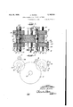
Figure 1 is a plan view, more or less diagram# matic, of a power transmission gearing assembly to which my invention is applied;
Figure 2 is a diagrammatic side elevation showing the various gearing assemblies and their relative centers and location.
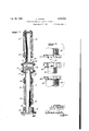
y Figure 3 is a longitudinal section of one of the drive pinion assemblies;
d Figure 4 is a side elevation of the inner ends of the pinion shaft sections and the torque shaft,
Figure 5 is a longitudinal section of a modified form of drive pinion assembly,
Figure 6 is a side elevation of the driven ends of the pinion shafts of Figure 5; and
Figure 7 is a side elevation, partly in section,
pulsion shaft gear The bearings I4 and I4' journal the countershaft I1 on which is mounted the transmission gear |8 which meshes with the propulsion shaft gear Il.
At its opposite ends, the countershaft I5 supports the transmission gears I9 and I9' respectively which are of larger diameter than the gear I6. The countershaft I1 at its outer endls supports the transmission gears 20 and 20' respectively which, as shown, have the same diameter as the gears |9, but which may be a different diameter. The various gears are of the double helical or herringbone type.
I have shown three drive pinion assemblies A, B and C adapted for selective connection with driving sources such as turbines or Diesel engine (not shown). The assemblies A and B are asso ciated with the transmission gears on the countershaft I1, and the assembly C is associated with the gears on the countershaft I5.
Figures 3 and 4 show the structure and arrangement of the drive assembly B which is inwardly of and above the countershaft l1 and comprises the fore and aft drive pinions 2| and 2| which mesh respectively with the intermediate gears 20 and 29' on the countershaft I1. The pinion 2i is secured on, or may form an integral part of a tubular shaft section 22 and the `pinion 2| has a similar shaft section 22. 'Ihe shaft sections are axially aligned, the section 22 being journalled in bearing structures 23 and 24 and the shaft section 22 being journalled in bearing structures 23 and 24'. These various bearings together with the bearings for the propeller shaft I0 and the countershafts I5 and i1 form a rigid part of a supporting base or frame (not shown).
At their inner ends, the Ishaft sections 22 and 22 have heads 25 and 25', respectively, received within the ends of the housing 26 of a coupling device D. The heads have splines or teeth 21 and 21' respectively for meshing with the splines or teeth 28 and 28' on the coupling housing 26, the splines being opposed and of the single helical type.
Extending through the bore of the outer shaft section 22 is a torque shaft 29 which at its` inner end projects into the coupling housing 26 and has the head 30 provided with splines or teeth 3| for engagement with the splines 32 on the housing 26 between the splines 28 and 28' and with engaging surfaces parallel to the axis of torque shaft 29. The torque shaft is suitably journalled as by bushings 32 in the shaft 22 and at its outerend is secured to the inner member 313 of a coupling structure E whose outer member 34 has spline connection 35 with the inner member 33 and is adapted for connection with a driving source such as a turbine or engine, the spline connections 3| and 35 compensating for any error or change under operating conditions in the axial alignment of the driving source shaft andA the. gear assembly so that the power will be smoothly delivered.
By centralizing the coupling device between the pinion shafts, the shafts may be of equal length and comparatively short with corresponding reduction of their bending or twisting movements.
The spline connection 35 permits axial shift of the shaft 29 relative to the coupling member 34, and the spline connection between the coupling housing 26 and the heads of the shafts 22 and 22' also permits relative axial movement of the shaft sections. The shaft section bearing structures are also sufficiently displaced from the ends of placement of the shaft sections in the bearings.
The herringbone pinions 2| and\2| may thus follow lateral displacement of the intermediate gears on the countershaft I1 so as to maintain proper tooth mesh engagement. 'I'he peripheries of the shaft heads 25 and 25 and of the head 30 of the torque shaft carry the coupling housing 26 and are slightly rounded transversely to compensate for mis-alignment of the pinion shafts.
The opposed single helical spline coupling between the shafts and the coupling housing will produce a condition of equilibrium between the forward and aft gear members which will compensate for slight differences in radial alignment in both ahead and astern and will provide for lateral movement to conform with the requirements of expansion under heat of the intermediate pinion members on the countershafts, and will allow the respective pinion members to compensate for any wobble or for end motion of their mating gear members caused by inaccuracies of manufacture or installation. Thus the intermeshed double helical gears may accurately aline and register and adapt themselves for the most efficient driving connection and transmission and equal distribution of the load.
The structure and operation of the driving pinion assembly C is the same as that of the assembly B, the pinions 36 and 36 being larger than the pinions of the assembly B to compensate for the difference in speed of the respective driving sources B and C. The torque shaft 29 of the assembly C terminates in a coupling 31 for connection with its driving source, this coupling being substantially of the same construction as the coupling E for the drive assembly B.
The driving assembly A may be the same as the driving assemblies B and C and provided with drive pinions meshing respectively with the intermediate transmission gears 20 and 20. However, I have shown the assembly A comprising a short shaft 38 journalled in suitable bearings 39 between which the shaft supports avdrive pinion 40 which meshes with the intermediate transmission gear 20, the shaft being provided at its outer end with a coupling structure 4| for connection with a driving source. The other assemblies B and C are used for high power driving and the use of the center drive and coupling connection in association with herringbone gears will compensate for inaccuracies which might otherwise disturb and prevent efficient operation, and will permit proper and efficient meshing of the various gears so that they will run quietly, and the entire operation will be in a condition of load equilibrium for smooth, efcient functioning. In the modified arrangement of Figures 5 and 6. the coupling structure D, instead of being centrally located between the aligned drive-pinion shafts, is located at the outer end of the shaft structures. The supporting shaft 42 for the drive pinion 2| is tubular and journaled in bearing structures 43 and 44 adjacent to the ends of the pinion. The supporting shaft 45 for the drive pinion 2|' is journaled in bearing structures 46 and 41 adjacent to the ends of the piniony the shaft 45 extending outwardly through the tubular shaft 42 oi the pinion 2|, a bushing 48 in the outer end of the shaft 42 providing bearing support for the outer end of the shaft 45. At its outer end the shaft 42 has the coupling head 49 provided with helical splines or teeth 50. The outer end of the shaft 45 has a head 5| secured thereto which has helical splines or teeth 52, the
.head l being of smaller diameter than the head 49. The coupling frame 53 surrounds the shaft heads and has opposed helical splines 54 and 55 for meshing respectively with the helical splines 50 and 52 on the heads.
The coupling frame 53 has the tubular drive link 56 secured thereto which link terminates at its outer end in a ange 51 having straight teeth or splines 58 thereon meshed by the teeth or splines 59 on the driving head 60 and4 parallel to the axis of the drive shaft 6I extending from the driving source (not shown).
Upon rotation'of the driving coupling frame 53, the opposed helical spline connections thereof with the shaft heads will cause the pinion shafts to'be simultaneously driven, the splines being of the single helical type, and with the driving and driven splines free for relative axial movement, the drive pinions will be free to follow any radial and axial displacement of the transmission gears meshed thereby, the gears being of the double helical type. The-spiiruconnection of the driving link 56 with the drivihgshaft 6i will permit relative axial movement, the splines which terminate in the coupling frame 53 functioning more or less as a universal drive connection between the drive shaft and the pinion shafts. The driving power is thus transmitted to the pinion shafts without disturbing the radial alignment or register of the double helical teeth of the gearing elements and with compensation for axial misalignment of the pinion shafts.
Instead of the spline connection between the coupling frame and the pinion shafts, as shown inFigure 3, a spring connection could be used. Figure I shows such arrangement, the head 62 of the torque shaft 29 extending into and being secured to the coupling frame 63,*the head carrying spring coupling members 64 and 64' engaging respectively with the heads 25 and 25 of the pinion shafts 22 and 22' so that rotation of the coupling frame is yieldingly transmitted to the pinion shafts for relative displacement of said shafts to permit the drive pinions thereon to maintain accurate meshing engagement with the transmission gears. l p
Although I have shown a double helical gearing assembly as a preferred arrangement, my invention c ould be applied to a single helical gearing or straight spur gearing assembly.
I have shown practical embodiments of the features of my invention but I do not desire'to be limited thereto as changes and modicat'ions maybe made without departing fromthe scope and spint of the invention.
I claim Ias follows:
.1. In a propulsion system of the class described, a propulsion shaft having a gear thereon, a countershaft having a pinion thereon meshing with said propulsion shaft gear, transmission gears at the opposite ends of said countershaft, and a drive pinion assembly for said transmission gears, said assemblycomprising drive pinions meshing with said transmission gears, axially aligned supporting shafts for said drive pinions, a coupling housing having spline connection with the ends of said pinion shafts, andy a torque shaft concentric with said coupling housing having spline connection therewith and being adapted for connection with power source.
2. In a propulsion system of the class described, a'driven shaft having spaced apart gears thereon, 4and a drive -pinion assembly for said l gears comprising pinions meshing with the respective gears, axially aligned shafts supporting said pinions at their outer ends, a coupling device having single helical drive connections with the ends of said pinion shafts, and a torque shaft concentric with said coupling and having spline vdriving connection therewith and adapted for connection with a power source. h
3. In a propulsion system of the class described, a driven shaft having two spaced apart gears thereon, and driving assembly for said gears comprising drive pinions meshing with said gears, shafts for said pinions, a coupling device receiving the inner ends of said shafts and having helical spline driving connection therewith, and a torque shaft extending through one of said pinion shafts and adapted to transmit driving power from a power source to said v'coupling device.
4. In a propulsion system of the class described, a driven shaft having two spaced apart gears thereon, and a driving assembly for said gears comprising drive pinions meshing with said gears,
supporting shafts for said pinions terminating at' their inner ends in drive flanges having splines -thereon at angles with the shaft axes, a coupling device surrounding said splined anges and being splined for cooperation with said iiange splines for drive of said pinion shafts, and a torque shaft extending through one of said pinion shafts and adapted at its outer end for connection with a power source, the inner end, of said torque shaft having a splined driving flange for cooperation with splines on said coupling device for driving of said coupling device and the shaft splined thereto.
ing opposed single helical spline connection therewith, and means for driving said coupling.
6. In a propulsion system of the class described, a driven shaft having spaced apart gears thereon, and a driving assembly for said gears comprising driving pinions for the respective gears, supporting shafts for said pinions extending therefrom, a
Ydriving coupling for said pinion shafts having opposed single helicalspline connection therewith, and means for driving said coupling, said gears and pinions being of the double helical type.
7. In a propulsion system of the class described, a driven shaft having spaced apart transmission gears thereon, and a drive pinion assembly comprising drive pinions meshing with said gears, separate axially aligned shafts for said pinions on the outer ends of which said pinions are mounted, a drive coupling device having opposed single helical spline driving connection with the inner ends of said pinion shafts, and a drive shaft for said coupling device extending therefrom through one of said pinion shafts and adapted for connection with a power source.
8. In a propulsion system of the class described, a driven shaft having spaced apart gears thereon, and a drive pinion assembly for said gears comprising pinions meshing with the respective gears, axially aligned shafts supporting said pinions, adjacent ends of said shafts terminating in cou- -pling heads, a coupling frame receiving said heads and having yieldable spring driving connection therewith, and a drive shaft coupled to said coupling frame. v
AUSTIN KUHINS.
Priority Applications (1)
| Application Number | Priority Date | Filing Date | Title |
|---|---|---|---|
| US194095A US2148564A (en) | 1938-03-05 | 1938-03-05 | Power transmission gearing assembly |
Applications Claiming Priority (1)
| Application Number | Priority Date | Filing Date | Title |
|---|---|---|---|
| US194095A US2148564A (en) | 1938-03-05 | 1938-03-05 | Power transmission gearing assembly |
Publications (1)
| Publication Number | Publication Date |
|---|---|
| US2148564A true US2148564A (en) | 1939-02-28 |
Family
ID=22716277
Family Applications (1)
| Application Number | Title | Priority Date | Filing Date |
|---|---|---|---|
| US194095A Expired - Lifetime US2148564A (en) | 1938-03-05 | 1938-03-05 | Power transmission gearing assembly |
Country Status (1)
| Country | Link |
|---|---|
| US (1) | US2148564A (en) |
Cited By (8)
| Publication number | Priority date | Publication date | Assignee | Title |
|---|---|---|---|---|
| US2578015A (en) * | 1945-07-10 | 1951-12-11 | Gustav A Reinhard | Transmission |
| US2639624A (en) * | 1949-08-19 | 1953-05-26 | Falk Corp | Yieldable power transmission |
| US2660064A (en) * | 1951-08-20 | 1953-11-24 | George R Stibitz | Mechanical differential |
| US2671360A (en) * | 1949-08-19 | 1954-03-09 | Falk Corp | Variable-speed transmission |
| US2734396A (en) * | 1956-02-14 | Twin drive and driven power | ||
| US4114468A (en) * | 1973-02-16 | 1978-09-19 | Universal Power Corporation | Drive means for electric generators particularly adapted in floating power plant |
| FR2402124A1 (en) * | 1977-08-31 | 1979-03-30 | Mannesmann Ag | MECHANICAL POWER REDUCER |
| US4946428A (en) * | 1986-11-18 | 1990-08-07 | Barozzi Gian P | Compact play-free speed-reducing transmission |
-
1938
- 1938-03-05 US US194095A patent/US2148564A/en not_active Expired - Lifetime
Cited By (8)
| Publication number | Priority date | Publication date | Assignee | Title |
|---|---|---|---|---|
| US2734396A (en) * | 1956-02-14 | Twin drive and driven power | ||
| US2578015A (en) * | 1945-07-10 | 1951-12-11 | Gustav A Reinhard | Transmission |
| US2639624A (en) * | 1949-08-19 | 1953-05-26 | Falk Corp | Yieldable power transmission |
| US2671360A (en) * | 1949-08-19 | 1954-03-09 | Falk Corp | Variable-speed transmission |
| US2660064A (en) * | 1951-08-20 | 1953-11-24 | George R Stibitz | Mechanical differential |
| US4114468A (en) * | 1973-02-16 | 1978-09-19 | Universal Power Corporation | Drive means for electric generators particularly adapted in floating power plant |
| FR2402124A1 (en) * | 1977-08-31 | 1979-03-30 | Mannesmann Ag | MECHANICAL POWER REDUCER |
| US4946428A (en) * | 1986-11-18 | 1990-08-07 | Barozzi Gian P | Compact play-free speed-reducing transmission |
Similar Documents
| Publication | Publication Date | Title |
|---|---|---|
| US4590820A (en) | Rotational power transmission apparatus | |
| US4118997A (en) | Bevel gearing | |
| US4388838A (en) | Multiple countershaft simple transmission | |
| US2148564A (en) | Power transmission gearing assembly | |
| US2516077A (en) | Gear set | |
| White | Design study of a split-torque helicopter transmission | |
| US4399719A (en) | Twin screw extruder with power branching gearing | |
| US2505002A (en) | Planetary gearing | |
| US3486832A (en) | Helicopter rotor transmission system | |
| US2479406A (en) | Bevel gear drive | |
| US2209120A (en) | Power transmission mechanism | |
| US1740756A (en) | Power-transmission gear | |
| US1990606A (en) | Shafting for power transmission | |
| EP3287654A1 (en) | Flexible coupling arrangements for drive systems | |
| US4776232A (en) | Gearbox arrangement for an industrial robot | |
| US10364038B2 (en) | Propulsion unit for an aircraft | |
| US6122985A (en) | Torque-dividing transmission, particularly for aircraft | |
| US3808913A (en) | Epicyclic gear train | |
| US2293279A (en) | Aircraft transmission | |
| EP1295788A2 (en) | Hybrid power input quill for transmissions | |
| US3564937A (en) | Mechanical drive with angle power transmission | |
| US3106067A (en) | Turbine power plants | |
| US3309936A (en) | Reduction gear construction | |
| US1551844A (en) | Gear train | |
| US2133102A (en) | Drive connection |