US2141237A - Electric telegraphy - Google Patents
Electric telegraphy Download PDFInfo
- Publication number
- US2141237A US2141237A US25051A US2505135A US2141237A US 2141237 A US2141237 A US 2141237A US 25051 A US25051 A US 25051A US 2505135 A US2505135 A US 2505135A US 2141237 A US2141237 A US 2141237A
- Authority
- US
- United States
- Prior art keywords
- relay
- grid
- tube
- circuit
- dash
- Prior art date
- Legal status (The legal status is an assumption and is not a legal conclusion. Google has not performed a legal analysis and makes no representation as to the accuracy of the status listed.)
- Expired - Lifetime
Links
- 238000004804 winding Methods 0.000 description 26
- 230000007935 neutral effect Effects 0.000 description 21
- 210000002105 tongue Anatomy 0.000 description 13
- 230000001276 controlling effect Effects 0.000 description 11
- 239000004020 conductor Substances 0.000 description 10
- 230000005540 biological transmission Effects 0.000 description 6
- 230000001172 regenerating effect Effects 0.000 description 5
- 238000000034 method Methods 0.000 description 3
- 125000004122 cyclic group Chemical class 0.000 description 2
- 230000010355 oscillation Effects 0.000 description 2
- 230000001105 regulatory effect Effects 0.000 description 2
- OZAIFHULBGXAKX-UHFFFAOYSA-N 2-(2-cyanopropan-2-yldiazenyl)-2-methylpropanenitrile Chemical compound N#CC(C)(C)N=NC(C)(C)C#N OZAIFHULBGXAKX-UHFFFAOYSA-N 0.000 description 1
- 230000002238 attenuated effect Effects 0.000 description 1
- 229910052729 chemical element Inorganic materials 0.000 description 1
- 238000006243 chemical reaction Methods 0.000 description 1
- 230000001419 dependent effect Effects 0.000 description 1
- 238000007689 inspection Methods 0.000 description 1
- 230000008929 regeneration Effects 0.000 description 1
- 238000011069 regeneration method Methods 0.000 description 1
- 230000000284 resting effect Effects 0.000 description 1
Images


Classifications
-
- H—ELECTRICITY
- H03—ELECTRONIC CIRCUITRY
- H03M—CODING; DECODING; CODE CONVERSION IN GENERAL
- H03M5/00—Conversion of the form of the representation of individual digits
Definitions
- This invention relates to new and useful improvements in electric telegraphy, and more particularly to circuit arrangements of translating or converting telegraph code signals composed of a certain number of elements into telegraph codes composed of a different number of elements.
- One of the objects of the present invention is to provide for the transmission of a two-element code which may be easily read by the average telegrapher and for simple and efficient circuit arrangements for translating from a threeelement code into a two-element code, and vice versa, with or without means for regenerating impulses that may have become mutilated during transmission.
- the translation is accomplished by interposing a time delay circuit between a relay associated with the input and a relay associated with the output end of a telegraph circuit.
- the time delay circuit comprises a vacuum tube or a plurality of vacuum tubes so arranged that by suitably adjusting or varying the potential on the grid electrode of the tube, the length or spacing of the signals may be controlled through the agency of the output relay.
- the translation of a three-element code into a two-element code may be controlled by timing H the operation in a predetermined manner of the impulse transmitting relay associated with the transmitter, depending whether the relay is operated in accordance with dash or dot signals.
- the arrangement is such that the translation can be effected without any special means being provided of maintaining transmitting and receiving equipments in synchronism.
- Still another feature of the invention has to do with the actuation of a direct Writer in accordance with a code and in response to signals received in a different code.
- FIG. 1 illustrates the two-element cable code contrasted with the usual three-element code
- Fig. 2 the arrangement at the sending station for translating the three-element code into the two-element code
- Fig. 3 the arrangement for translating the twoelement code into the three-element code at the juncture of a land line with a cable;
- Fig. 4 the arrangement for regenerating and converting three-element cable code signals where a long cable works into a land line;
- Fig. 5 an arrangement for translating into a two-element code three-element code signals which have not been greatly mutilated in their transmission over a cable;
- Fig. 6 a twoto three-element translator having a direct writer output.
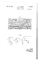
- Fig. 1 graplr'cally illustrates the usual threeelement cable code contrasted with the two-element code of the present invention.
- the three elements of the usual cable code are; positive, negative, and absence of current. If we divide the time during which a signal is applied into three units, a dot consists of positive potential applied for three units of time, a dash of negative potential applied for three units of time, and spacing between dots and dashes is indicated by the absence of current for three unit lengths of time. In my two-element code no negative potentials are applied, the distinction between a dot and a dash being that the dot is represented by positive potential applied for one unit of time and a dash of positive potential applied for two units of time. Spacing is indicated by the absence of current for three unit lengths of time. The two elements of the code consists, therefore, of marking and spacing.
- Each two-element cable code dot, dash or spacing signal requires the same amount of time for its transmission.
- the two-element cable code dot consists of one unit spacing, one unit marking and one unit spacing, a total of three units; a dash of two units marking and one unit spacing, again a total of three units; and a space of three units spacing.
- the three units of time required for sending each element of this code occupy the same period as corresponding periods in the three-element code, i. e., one centerhole in the usual three-element cable code sending tape. No signals need be stored at a translator station. It is obvious from an inspection of Fig. 1 that the two-element code when recorded by a direct writer may be as easily read as the three-element code.
- the third or last unit of each code signal is always spacing, whether the signal is a dot, a dash or spacing.
- the ending of the marking interval on both the dot and dash signals occurs at the end of the second time unit.
- the interval between the end of the marking of the dash and the end of the marking of the dot is exactly three units of time or one centerhole on the sending tape.
- a similar interval of time separates the end of the marking of the dot and the end of the marking of the next dash.
- FIG. 2 The manner in which such two-element cable code may be transmitted from a tape perforated in accordance with the usual three-element cable code is diagrammatically shown in Fig. 2, illustrating only such, parts of a standard automatic transmitter operating at constant speed as are necessary for an understanding of the present invention.
- a transmitting relay 1 connected with the positive pole of grounded battery may have its circuit completed to ground over a contact 2 or a contact 3.
- the open or closed condition of hese contacts depends on the position of a dash pecker 4 and a dot pecker 5, respectively, which, as well known, bear against the perforated transmitting tape and are permitted to rise under spring tension if a hole is punched in the tape.
- cams or interrupters 8 and I mounted on a common shaft 8 which is constantly rotated by the automatic transmitter at the rate of one revolution for each centerhole.
- the conducting portion of cam 6 extends over two-thirds of its circumference, and that of cam I over one-third of its circumference.
- a wiper 9 connected with contact 2 bears against cam 6 and a wiper l connected with contact 3 bears against cam I.
- the cams are conductively connected with shaft 8 and the latter is grounded.
- the telegraph line H is connected with one terminal of the winding of a line relay l2, the other terminal of which is grounded.
- the arrangement includes two timing circuits one of which is for distinguishing between dots and dashes by the duration of the marking time and the other to space the dot and dash transmitting relays when no marking signal has been received for a predetermined time interval.
- the two circuits are respectively controlled by means including vacuum tubes l3 and I4 having any suitable arrangement of electrodes.
- the two terminals of filament 2! of tube l3 are connected with the two terminals of ungrounded battery over equal resistances 22 in the two legs of the circuit.
- Filament 23 of tube I 4 is similarly connected over resistances 24.
- the potential of the filament is, therefore, approximately midway between the positive and negative terminals of the main power battery indicated at 25.
- the line relay I2 is tie-energized and connects the negative pole of battery 25 over its armature and back or spacing contact to one end of the winding of a control relay 25, the other end of which is connected over a resistance 2'! to the positive pole of battery 25.
- the control relay 26 becomes energized and connects the negative pole of the battery through its front contact and armature and a resistance 28, to grid 29 of tube [3 and to one plate of the condenser I1; the other plate is connected to the positive pole of the battery.
- the condenser will, therefore, receive a negative charge on the grid side and the grid 29 becomes very negative with re spect to the cathode 2
- relay 15 will now become energized.
- the shunt resistance I9 of condenser ii is so adjusted that the plate relay 15 will not be operated when a dot is received, and will be operated when a dash is received.
- the armature of line relay l2 must be attracted and that of control relay 26 released for more than one unit of time (in practice, one and one-half units to time) before the negative charge from grid 29 leaks off sufliciently to permit the operation of plate relay l5.
- the energization of relay l5 will indicate, therefore, that a dash was received.
- the relay 25 would have been energized, whereby upon the de energization of the line relay l2, a circuit would be closed from the negative pole of battery over the armature and back contact of relay [2, resistance 3
- vacuum tube 14 and associated circuits The purpose of vacuum tube 14 and associated circuits is to restore the dot and dash transmitters 32 and 33 to their spacing position, so as to send a spacing signal into the cable 33 when no two-element marking signals are received for a predetermined length of time.
- the relay [2 When the relay [2 is energized the negative pole of the battery is connected over the armature and marking contact of this relay, a resistance 39 and thence to condenser l8 and grid 43 of vacuum tube M. This will negatively charge condenser l8 and grid d3, preventing the flow of current to plate 4! of tube l4 and the winding of spacing relay It.
- the spacing relay can, therefore, not become energized.
- variable resistance 25! is so adjusted that the negative charge can leak off through it sufficiently to permit the operation of relay l6 only if the relay 82 remains de-energized for three units of time of the twoelement cable code, that is to say, while a spacing signal is transmitted.
- relay l6 attracts its armature, breaks the connection of conductor 34 to the positive pole of the battery, and connects the positive pole over its front contact, conductor 42 and the bottom windings of relays 32 and 33, and a resistance 43, to the negative pole of the battery. Energization of these two windings will move both armatures 35 and 36 onto their spacing contacts, connecting ground with cable 38 which, in the cable code, indicates spacing.
- FIG. 4 shows a circuit arrangement for converting such regenerated threeelement code messages into a two-element code. Since cable code regenerators are well known their details are not illustrated except for the usual regenerator tuning fork 5i] and the output terminals 5
- tact 57 is closed simultaneously with the work pick-up contact so that the tongues of the dot and dash relays 52 and 55 will be moved only while the tuning fork 50 is closing the contact 51. Furthermore, this contact is so adjusted that a relay 59 connected with plate 60 of the tube 58 is invariably unoperated during every third time interval. While the fork 50 is marking, negative poten al is applied over resistance SI to grid 62 of the tube 58, and over resistance 63 to the condenser This will negatively charge the condenser and apply a negative potential on grid 62, whereby no current can flow to plate 60 from filament 55, the two terminals of which are con: nected with the two poles of battery 53 over resistances 55. Therefore, no current, i.
- the resulting plate current in the tube 58 will operate the relay which will become energized and connect the positive pole of grounded battery with the line
- the dot relay 52 is in an operated position when the tuning fork 59 leaves its contact 51, it will discharge condenser 64 over a variable resistarmature and front contact of relay 52 and a relatively low resistance 19 to the positive pole of the battery.
- the resistance 69 is so adjusted that the time required for the negative charge to leak off grid 62 will take one more unit of time than when the dash relay 55 was operated, whereby relay 59 will be energized only for a length of time necessary for the sending of a dot of the two-element code to the line 61.
- a dot and a dash polar relay and i3! respond to the signals received over cable terminals 82 and 83. These relays control by means of their armatures 84 and 85 a tube 85 which, with its associated apparatus, controls in turn the conversion of the three-element into the two-element code.
- a relay 8'? connected with the plate 88 of tube 85 controls a so-called slave relay 89.
- and assoed equipment are provided for the purpose i reducing the dash length signals received from into dot length signals.
- a tube 92 with its ate relay and associated timing circuits compensates for the characteristic distortion in the received signals.
- e circuit of vacuum tube 86 is 50 arranged may be obtained, as well as the desired ratio or" the marking and spacing time controlled by this relay.
- These resistances may be adjusted to value of from O-100,000 ohms and are connccted in series to the positive pole of 110 volt generator 95. Midway between the two resistances is connected the positive pole over a condenser 9'I.
- the two resistances in series are connected also over a wire 98 with grid 99 of vacuum tube 86 through an intervening l-megohm resistance I00, and with one plate of condenser IOI, the other plate of which is connected to the positive pole over a 2500-ohm resistance I02.
- a second grid I03 of tube 88 and similar second grids of the two other tubes are connected to the positive pole over a 5000-ohm resistance I04. These second grids play no role in the functioning of these tubes and are illustrated merely because three-element tubes are not as easily available as double-grid tubes.
- Relay 59 which is operated over the circuit extending from the positive pole over resistance i92 and the spacing contact and armature of relay 8'5 to the negative pole, will, of course, mark for two-thirds and space for one-third of the time. This is the correct duration of contact time for dash output in the two-element code.
- the plate relay 93 associated with tube 92 controls the stopping of tube 85 from oscillating.
- the tube 8'3 is free to oscillate in the manner described under the control of resistances 94 and 95 only when relay 93 is de-energized and its armature is on the spacing contact. While the armature is on the marking contact, it connects the positive pole direct over resistance I00 with grid 99 and with the condenser NH.
- the change in the potential of grid 99 is controlled or timed not only when the grid is negative and approaching a positive condition, but also when it is positive and approaching a negative condition. If the grid potential were plotted against time, the resultant graph would have a saw-toothed appearance and the line going from negative to positive would have less slope than when going from positive to negative.
- the start of a cable code dot or dash which directly follows a spacing signal occurs relatively early as compared with the start of a dot directly following a dash or a dash directly following a dot. This is called the characteristic distortion of a cable code and the present circuit arrangement is arranged to compensate for it.
- the tube 88 will now start operating in the manner previously described to vibrate the armatures of relays 81 and 89 at centerhole speed.
- negative potential is applied through the armature and front contact of this relay, conductor H5 and resistance I08, to grid E09 of tube 92. This will prevent any clipping of the marks from relay 89 in case the received signal should be clipped, since the negative charge on grid I09 prevents the untimely energization of relay 93.
- Tube 90 and its associated relay SI and circuits reduce the dash length signals repeated by relay 89 into dot length signals for transmission over a land telegraph line I I6.
- the relay 9I may be energized by space current flowing from cathode II! of tube 90 to plate II8 of the tube while grid II9 is positive with respect to the cathode.
- the grid is connected over a l-megohm resistance I20 with a junction point I2I with which are connected:
- the resistance I24 is adjusted to delay the twoelement dot by one-third of a centerhole. If the received cable signal is a dash, then no delay is required. When the dash relay is operated it will apply positive potential over conductor R28 to grid II9 and cause immediately the energization of relay 9I, since as long as dash relay 8! is marking, the variable resistance PM is shunted by the comparatively low resistance I01.
- is connected by throwing switch I29 into the lower or testing position so that the percentage of marking of this relay is directly indicated on a milliammeter I28 and, at the same time, the marks are recorded on one pen of a double pen direct writer connected through a jack I30.
- the other pen of the direct writer should record the received cable signals.
- the tongue of the dash relay BI is held to 1e marking contact and the beats of the translator are compared with received signals.
- the frequency is so adjusted that the beats on the tape are of the same frequency as the centerholes of the received signal.
- the adjustment for frequency is made by means of the variable resistances 94 and 95.
- Adjustment for percentage marking on I28 is made by maintaining a suitable ratio between 94 and 95. This adjustment will be correct when the beats are of the same frequency as the incoming signals and 62 marking is indicated by meter I 28.
- the dot relay tongue 84 is now held against its marking contact and the percentage marking is observed.
- the resistance I24 is adjusted so that the percentage marking be 33
- the input of the translator is now connected to the received cable signals. All capacity is removed from condenser H2 and the distortion observed on the direct writer of the two-element output signals from the translator.
- the gap between the first dash and dot of the letter C will be slightly greater than between the second dash and dot.
- the capacity of condenser H2 is now slightly increased until there is no distortion on the letter C.
- the translator is now ready for operation.
- Fig. 6 shows an arrangement for translating a two-element code into a three-element cable code direct writer record.
- the direct writer diagrammatically indicated at 290 is provided in the plate circuit of a vacuum tube 20I and is shunted by a lOO-ohm resist ance 292 so that only a portion of the plate current passes through the coil of the direct writer.
- 1000-ohm resistances 203 and 204 are used as a voltage divider or potentiometer to apply a reduced voltage to plate 205 of tube 20I.
- the resistances in the plate circuit are so proportioned and arranged that when grid 206 of the tube is negative with respect to the cathode 23?, no plate current will flow and the pen of the direct writer 290 will not be deflected. This condition will be maintained when a dot received on telegraph line 208 is recorded.
- Grounded polarized line relay 209 remains de-energized with its tongue 2 I0 against the spacing contact, closing a circuit from the negative pole of volts generator 2I I, the windings of relays 2I2 and 2I3 in series, a 1500-ohm resistance 2I4 midway between the two generators 2 I I. Both relays become energized.
- grid 2I5 of a vacuum tube 2I6 becomes positive with respect to cathode 2
- This relay will connect the negative pole over a 10,000-ohm resistance 220 and the center tap of the two generators 2 I I in parallel over a zero adjustment potentiometer 22I, conductor 222 and a 2.5 megohm resistance 223 to the grid 206 of tube MI.
- the potentiometer 22I is so adjusted that required grid potential is applied for permitting the flow of sufficient plate current in tube 20I for the direct pen writer to assume the abovementioned intermediate position.
- the line relay tongue 2I0 engages its marking contact and applies negative potential over a 200-ohm resistance 224 to grid 2I5 of tube 2I6 through an intervening 2.5-megohm resistance 225 and to a condenser 226.
- the other plate of the condenser is connected to the positive pole and the two plates are shunted by a variable resistance 221 and a fixed 10,000-ohm resistance 228.
- the condenser 226 will be quickly charged negatively as well as the grid 2I5, stopping the flow of plate current in tube 2I6 and de-energizing relay 2I9. The latter will disconnect the zero adjustment potentiometer 22I from grid 206 of tube 20I.
- Condenser 235 is much larger than condenser 229, whereby the potential of 235 will be A small grid condenser 229 only slightly altered when this circuit is estab- 15 lished. Condenser 229 will now be of the same potential as 235 and grid 206 of tube 2!!! will be of a similar potential.
- condenser 229 wi l not have sufiicient charge to render grid 206 positive with respect to the cathode, whereby no plate current will flow to energize the direct writer The latter will record a dot.
- the correctness of the setting of dot-dash adjustment rheostat 23! will be indicated by the amplitude of the dashes on the direct writer 2013. Too little resistance will be indicated by dots of less than normal amplitude. The amount of resistance required to give an occasional dot of less than normal amplitude should be noted and the resistance at which dashes of less than full amplitude occur should also be noted.
- the rheostat 239 should be kept at an intermediate value.
- the space adjustment rheostat 221 is regulated to make the dots or dashes preceding spaces of the proper length.
- the zero adjustment potentiometer 22! should be regulated to'make the zero line as indicated on the direct writer come midway between the dot and dash lines.
- a telegraph transmitter for converting a three-element code into a two-element code, a source of current, a transmitting relay having a ontact connected with said source, a circuit for said relay, means responsive to the three-element code for controlling said circuit, and timing means for closing said circuit for two-thirds and opening it for one-third of a time unit when a dash signal occurs in the three-element code, and for closing the circuit for one-third and opening it for two-thirds of said time unit when a dot signal occurs in the three-element code.
- a source of current for converting a three-element code into a two-element code
- a transmitting relay having an armature connected with the positive pole of said source
- a circuit for said relay having two branches, a dash pecker actuated contact in the first and a dot pecker actuated contact in the second branch, two interrupters, and means for rotating said interrupters in unison, one of said interrupters marking for two-thirds and spacing for one-third of a revolution the first branch, and the other marking for one-third and spacing for two-thirds of a revolution the second branch of the relay circuit.
- a relay associated with the input and a relay associated with the output end of said circuit means including a vacuum tube having a grid electrode for controlling the operation of the output relay in accordance with the operation of the input relay, and means for performing said translation including a variable grid leak reactance for timing the operation of said vacuum tube.
- an impulse receiving relay for translating a code composed of a plurality of elements into a code composed of a different number of elements
- a timing circuit for distinguishing between dots and dashes received by the marking time of said relay
- transmitting relay mechanism variably responsive to said timing circuit
- a second timing circuit to space the operation of said transmitting relay mechanism when said receiving relay does not mark for a predetermined length of time.
- a telegraph circuit for translating a two-element code into a three-element code, a neutral relay responsive to all marking and spacing impulses, a timing circuit for distinguishing dots and dashes by the marking time of said relay, dot and dash transmitting relays variably responsive to said timing circuit, and a second timing circuit to space said dot and dash transmitting relays when said neutral relay does not for a predetermined length of time.
- a source of current a neutral telegraph line relay having an armature connected with the negative pole of said source, a first and a second vacuum tube each having a cathode, a grid and an anode, a first relay having an armature connected with the positive pole and a winding connected between the positive pole and the anode of the first tube, a second relay having two windings one of which is connected between the positive pole and the anode of the second tube, a connection from the positive pole to the grid of each tube, each including a condenser and a variable resistance in parallel, a connection from the marking contact of said line relay to the grid of the first tube, a control relay, a connection from the spacing contact of said line relay in parallel to the winding of the control relay and the armature of said second relay, a connection from the negative pole to the grid of the second tube including the marking contact of the control relay, polarized dot and dash transmitting relays having windings controlled solely in the marking contact
- a telegraph circuit for regenerating cable code signals composed of a certain number of elements and translating them into a code composed of a different number of elements, dot and dash relays responsive to incoming code signals, a tuning fork, a time delay circuit jointly controlled by the tuning fork and contacts of said dot and dash relays, and a code transmitting relay controlled by said time delay circuit.
- a telegraph circuit for regenerating threeelement cable code signals and translating them into a two-element code
- neutral dot and dash relays responsive to incoming three-element cable code signals, a tuning fork having a contact closed only while one of said relays is moving its armature, a time delay circuit including a vacuum tube having a grid jointly controlled by the tuning fork contact and the armatures of said dot and dash relays, and a two-element code transmitting relay in the output circuit of said tube.
- a cable code signal regenerator having a tuning fork and two output terminals, a source of current, a neutral dot relay connected with one and a neutral dash relay with the other terminal, a vacuum tube having a cathode, a grid and an anode, a neutral transmitting relay connected with the anode, a con nection between the grid and the positive pole of said source including a relatively low resistance and a condenser in series, a second connection between the grid and the positive pole including a low resistance and a make contact of the dash relay in series, a third connection between the grid and the positive pole including in series a low resistance, a make contact of the dot relay and a variable resistance, and a connection between the grid and the negative pole including a contact closed by said tuning fork approximately for one-third of its operating time.
- a telegraph circuit for translating a cable of one type into a code of a difierent type, relay mechanism responsive to dot and dash signals received, means including a vacuum tube controlled by said relay mechanism for converting the code or" one type into a code of the different type, means including a second vacuum tube controlled by the output of the first tube for reducing dash length signals received from the first tube into dot length signals, and a timing circuit including a third vacuum tube to compensate for the characteristic distortion in the received three-element signals.
- dot and dash polar relays responsive to signals received, means including a vacuum tube controlled by said relays for converting the three-element code into a two-element code, a slave relay controlled by the output of said tube, means including a second vacuum tube controlled by said relay for reducing dash length signals received from the first tube into dot length signals, and a timing circuit including a vacuum tube to compensate for the characteristic distortion in the received three-element signals.
- a source of current means including a vacuum tube having a cathode, an anode and a grid, a grid circuit for said tube connected with a low capacitance grid leak, a relay in the output circuit of said tube controlling the two-element code output, means including two variable resistances and in parallel with the resistance, a device controlled by the three-element signals received for applying to the grid circuit positive potential, a relatively high capacitance connecting the positive pole to a point midway between the two variable resistances, means controlled by said relay for applying negative potential to said grid over one of said variable resistances, and a connection from the negative pole to said relatively low capacitance controlled by said relay.
- polarized dot and dash relays responsive to incoming signals, a vacuum tube having a cathode, a grid and an anode, a source of current, a grid circuit including a high resistance, the spacing contacts of said relays and a lower resistance in series to the positive pole, a relay in the anode circuit, impulse sending means operable in accordance with the incoming signals, means to prevent the operation of said impulse sending means while the anode relay is energized and for operating it when the anode relay is de-energized, a marking contact in the impulse sending means for connecting the negative pole to said high resistance, a leakage path from said grid to the negative pole in cluding in series a resistance, and a variable condenser and an intermediate resistance in parallel with the last mentioned resistance and condenser, the capacitance of said condenser being just sufficient to lag the de-energization of the anode relay by an interval of time equal to the
- a telegraph system input relay mechanism, three vacuum tubes each having a cathode, a grid and an anode, a relay connected with the anode of each tube, the anode relay of the third tube controlling the output of the system, a source of current, a slave relay controlled by the anode relay of the second tube, a variable capacitance, means jointly controlled by said capacitance, relay mechanism and slave relay for varying the potential on the first tube grid, a variable resistance, means jointly controlled by the variable resistance and the anode relays of the first and second tubes for varying the potential on the second tube grid, another variable resistance, and means jointly controlled by the last mentioned resistance, said slave relay and said relay mechanism for varying the potential on the third tube grid.
- polarized dot and dash input relays three vacuum tubes each having a cathode, a grid and an anode, a relay connected with the anode of each tube, a source 01" current, a connection between the grid of the first tube and the negative pole including a resistance and in parallel therewith, a resistance and a variable condenser, and a second parallel connection to the positive pole including spacing contacts of said input relays and a resistance in series, parallel paths between the grid of the second tube and the positive pole, the first including a condenser and resistance in series, the second marking contact of the anode relay of the first tube, the third two variable resistances in series, and the fourth one of said variable resistances and a condenser, two paths between the negative pole and the grid of the second tube, one including the marking contact of the anode relay oi the second tube a resistance and said one of said variable resistances in series, and the other the spacing contact of said anode relay of the second tube,
- a source of current a line relay responsive to two-element code signals, a direct writer for recording said signals in a three-element code, a vacuum tube having a cathode, a grid and an anode, means controlled by the incoming dot and dash signals for applying negative, positive and an intermediate potential to the grid, and an anode including said direct writer.
- a source of current means responsive to input signals in a certain code, a device in the output of said circuit operable in a different code, a vacuum tube having an anode, a cathode, and a grid, means controlled by the input signals for applying negative, positive and an intermediate potential to said grid, and an anode circuit including said device.
- a source of current a line relay responsive to two-element code signals, a direct writer for recording said signals in a three-element code, a vacuum tube having a cathode, a grid and an anode, means controlled by the incoming dot and dash signals for varying from negative to positive the potential on the grid, means responsive to incoming spacing signals for maintaining said grid at potential intermediate said negative and positive potentials, an anode circuit including said direct writer, and means for so proportioning said anode circuit that when the grid is negative no current will flow through the direct writer to deflect it, when the grid is positive maximum current will fiow through the anode circuit causing maximum defiection of the direct writer, and when the grid is at the intermediate potential enough current flows in the anode circuit to deflect the direct writer into a position intermediate zero and maximum deflection.
- a grounded polar line relay a source of current
- two vacuum tubes each having a cathode, a grid and an anode
- a relay connected with the anode of the first tube
- a direct writer connected with the anode of the second tube
- two neutral relays in series with the spacing contact of said line relay, a very high resistance connected with the grid of each tube
- two parallel branches from the very high resistance oi the first tube grid to the positive pole, one including a high capacitance and the other a variable resistance
- a potentiometer connected over a very high resistance between the negative pole and the marking contact of the first tube ano
- the method of electric telegraphy which comprises allotting to dot, dash and space signals predetermined periods of time, of the same length for each kind of signal, sending the dash signal only during the first and second one-third portions of a period, sending the dot only during the second one-third portion of a period, and sending the space signal during the entire period, whereby an easily legible two-element code may be transmitted.
- the method of electric telegraphy which comprises allotting to dot, dash and space signals predetermined periods of time, of the same length for each kind of signals, during the sending of a dot spacing the line for the first one-third of the period, marking it for the second one-third and spacing it for the third one-third, during the sending of a dash signal marking the line during the first and second one-third of a period and spacing it for the third one-third of the period, and for the sending of a spacing signal spacing the line for an entire period.
- a source of current for converting a three-element code into a two-element code
- a transmitting relay having an armature connected with said source
- a circuit for said relay having two branches, a contact operable in accordance with the dash signals of the three-element code in the first and a contact operable in accordance with the dot signals of the three-element code in the second branch, two interrupters, and means for rotating said interrupters in unison, one of said interrupters marking for two-thirds and spacing for one-third of a revolution the first branch, and the other marking for one-third and spacing for two-thirds of a revolution the second branch of the relay circuit.
- a relay responsive to impulses received, a timing circuit including a vacuum tube for distinguishing between dots and dashes received by the marking time of said relay, transmitting relay mechanism variably controlled by said vacuum tube, and a second timing circuit including a second vacuum tube to space the operation of said transmitting relay mechanism when said relay does not mark for a predetermined length of time.
- a source of current a telegraph line relay, a first and a second vacuum tube each having a cathode, a grid and an anode, a first relay connected with the anode of the first tube, a second relay connected with the anode of the second tube, a grid leak condenser for each tube, a variable resistance in parallel with each grid leak condenser, means controlled by said line relay for applying negative potential to the grids of said tubes, dot and dash transmitting relay mechanism, a circuit for said relay mechanism controlled by said first relay, a circuit for said relay mechanism jointly controlled by said first, second and line relays, and a third circuit for said relay mechanism jointly controlled by the line, first and second relays.
- a source of current a neutral telegraph line relay, a first and a second vacuum tube each having a cathode, a grid and an anode, a first relay connected with the anode of the first tube, a second relay having two windings one of which is connected with the anode of the second tube, a connection from the positive pole to the grid of each tube, each including a capacitance and a variable resistance in parallel, means operable upon the marking of said line r lay for applying negative potential to the grid of the first tube, a control relay controlled in the spacing contact of said line relay, a connection from the negative pole to the grid of the second tube including the marking contact of the control relay, polarized dot and dash transmitting relays having windings controlled in the marking contact of said first relay, second windings for said polarized relays jointly controlled in the spacing contacts of said first, second and line relays, third windings for said polarized relays, and a circuit for said third windings including in series the
- a telegraph circuit for regenerating three-element cable code signals and translating them into a two-element code
- neutral dot and dash relays responsive to incoming three-element cable code signals
- a tuning fork having a contact closed only while one of said relays is moving its armature
- a time delay circuit jointly controlled by the tuning fork contact and the armatures of said dot and dash relays, and a twoelement code transmitting relay in said time delay circuit.
- a cable code signal regenerator having a tuning fork and two output terminals, a source of current, a neutral dot relay connected with one and a neutral dash relay with the other terminal, a vacuum tube having a cathode, a grid and an anode, a neutral transmitting relay connected with the anode, a grid leak path including a condenser for said tube, a second grid leak path including a low resistance and a make contact of the dash relay, a third grid leak path including a low resistance, a make contact of the dot relay and a variable resistance, and a connection between the grid and the negative pole including a contact controlled by said tuning fork.
- a telegraph circuit means for alternately applying positive and negative potentials to the grid of the first tube, means including a variable resistance for timing the change of potential on said grid from negative to positive to take place at a certain rate, and means including the output circuit of the first tube and one of said variable resistances for timing the change of potential from positive to negative at a faster rate.
- a telegraph circuit according to claim 11 means for alternately applying positive and negative potentials to the grid of the first tube, and means including variable resistances for varying the potential on said grid twice as fast from positive to negative as form negative to positive.
- a telegraph circuit means including the second tube and variable resistances for alternately applying positive and negative potentials to the grid of the first tube, means including said variable resistances for timing the change of potential on said grid from negative to positive to take place at a certain rate, and means including the ouput circuit of the first tube and one of said variable resistances for timing the change of potential from positive to negative at a faster rate.
- a source of current means including a vacuum tube having a cathode, an anode and a grid, a grid circuit for said tube including a high resistance and controlled by the three-element signals received, a relay in the output circuit of said tube controlling the two-element code output, two branch paths for said grid circuit to the positive pole of said source, one including two variable resistances in series, and the other a relatively low capacitance, a path from the positive pole through a relatively high capacitance to a point in said one of said branch paths midway between the two variable resistances, a connection from said point to the negative pole including a low resistance and the marking contact and armature of said relay, and a connection from the negative pole to said relatively low capacitance including the armature and spacing contact of said relay.
- relay mechanism responsive to incoming signals, a vacuum tube having a cathode, .a grid and an anode, a source of current, a relay in the anode circuit, impulse sending means operable in accordance with the incoming signals and controlled by said relay, means controlled by the impulse sending means and said relay mechanism for varying the potential on said grid, and a leakage path for said grid to lag the deenergization of the anode relay by an interval or" time equal to the characteristic distortion of the incoming signals.
- relay mechansm responsive to incoming signals, a vacuum tube having a cathode, a grid and an anode, a source of current, means including said relay mechanism for applying positive potential to the grid, a relay in the anode circuit, impulse sending means operable in accordance with the incoming signals and controlled by the anode relay, a marking contact in the impulse sending means for applying negative potential to said grid, a leakage path from said grid to the negative pole including a capacitance just sufficient to lag the operation of the anode relay by an interval of time equal to the characteristic distortion of the incoming signals.
- a telegraph circuit according to clam 17, and a potentiometer in the anode circuit are identical to A telegraph circuit according to clam 17, and a potentiometer in the anode circuit.
- a telegraph circuit according to claim 18, and a potentiometer in the output circuit are provided.
- a telegraph circuit according to claim 18, a low capacitance grid leak condenser, a high capacitance condenser, and means controlled by the input signals for interconnecting said condensers.
- a source of current a polar line relay responsive to two-element code signals, a direct writer for recording said signals in a three-element code
- a Vacuum tube having a cathode, a grid and an anode
- means including said relay and controlled by the incoming dot and dash signals for applying negative and positive potentials to the grid means including said relay and responsive to incoming spacing signals for maintaining said grid at potential intermediate said negative and positive potentials
- an anode circuit including a resistance, a potentiometer and said direct writer, said anode circuit eing so proportioned and adjusted that when the grid is negative no current will flow through the direct writer to deflect it, when the grid is positive maximum current will fiow through the anode circuit causing maximum deflection of the direct writer, and when the grid is at the intermediate potential enough current fiows in the anode circuit to deflect the direct writer into a position intermediate zero and maximum deflection.
- a line relay In a telegraph system, a line relay, a source of current, two vacuum tubes each having a cathode, a grid and an anode, a relay connected with the anode of the first tube, a direct writer and a potentiometer connected with the anode of the second tube, two neutral relays in series with the spacing contact of said line relay, a
- a telegraph system comprising means for sending a dash signal only during the first and second one-third portions of a period and means for sending a dot signal only during the second one-third portion of a period.
- a telegraph system comprising means for translating standard three element code signals into two element code signals in which the dot and dash signals each are allotted equal perods of time, means for transmitting said two ele ment code signals, and translating means operative in response to said transmitted two element code signals for retranslating said two element code into a three element code.
- a telegraph system comprising means for sending a dash signal only during the first and second one-third portions of a period, means for sending a dot signal only during the second onethird portion of an equal period, and means responsive to said dash and dot signals for translating said signals into code elements comprising positive and negative impulses, of equal time duration.
- a telegraph system for converting a three element code into a. two element code, and reconverting said two element code into a three element code comprising a source of current, a transmitting relay having a contact connected with said source, a circuit responsive to the three element code for controlling said circuit, timing means for closing said circuit for two-thirds and opening it for one-third of a time unit when a dash signal occurs, and for closing said circuit for one-third and openng it for two-thirds of said time unit when a dot signal occurs in said three element code to transmit a two element code, an impulse receiving relay in said circuit, a timing means for distinguishing between dot and dash signals of said two element code by the marking time of said receiving relay, and a transmitting relay means variably responsive to said timing circuit.
Landscapes
- Engineering & Computer Science (AREA)
- Theoretical Computer Science (AREA)
- Inking, Control Or Cleaning Of Printing Machines (AREA)
Description
Dec. 27, 1938. A, (:QNNERY 2,141,237
ELECTRIC TELEGRAPHY Filed June 5, 1955 5 Sheets-Sheet 1 'FIG.
a a mwrc 2515 M100 1707 3 DOT H. DASH 043/1 3- SPA SPACE s- 3 1. [MFA/TC FIG.2
INVENTOR:
A TORNEY Dec. 27,1938. A; F. CONNERY ELECTRIC TELEGRAPHY' Filed June 5, 1955 5 Sheets-Sheet 2 INVENTOR: AZDH? E (DIV/VH2) ATTORNEY Dec. 27, 1938'. F., CONNERY ,1
ELEQTRIC TELEGRAPHY Filed June 5, 1935 5 Sheets-Sheet 3 FIG. 4-
INVF N TOR 1 om co/mm y Dec. 27, 1938. I 'A: F. CONNERY b 2,141,237
ELECTRI C TELEGRAPHY Filed June 5, 1935 5 Sheets-Sheet 4 FIG. 5
mvnvran; vl/w 7 5 41050 f. (MINE/2V -M y Wow! I A r nut-V Dec. 27, 1938. A, F. CONNERY ELECTRI C TELEGRAPHY Filed June 5, 1935 5 Sheets-Sheet 5 Patented Dec. 27, 1938 UNITED STATES PATENT OFFlCE ELECTRIC TELEGRAPHY Application June 5, 1935, Serial No. 25,051
51 Claims.
This invention relates to new and useful improvements in electric telegraphy, and more particularly to circuit arrangements of translating or converting telegraph code signals composed of a certain number of elements into telegraph codes composed of a different number of elements.
Systems of this nature are usually employed at points where telegraph signals are relayed from a land line into a cable or vice versa.
One of the objects of the present invention is to provide for the transmission of a two-element code which may be easily read by the average telegrapher and for simple and efficient circuit arrangements for translating from a threeelement code into a two-element code, and vice versa, with or without means for regenerating impulses that may have become mutilated during transmission.
In accordance with the present invention the translation is accomplished by interposing a time delay circuit between a relay associated with the input and a relay associated with the output end of a telegraph circuit. According to one feature of the invention, the time delay circuit comprises a vacuum tube or a plurality of vacuum tubes so arranged that by suitably adjusting or varying the potential on the grid electrode of the tube, the length or spacing of the signals may be controlled through the agency of the output relay.
According to another feature of the invention, the translation of a three-element code into a two-element code may be controlled by timing H the operation in a predetermined manner of the impulse transmitting relay associated with the transmitter, depending whether the relay is operated in accordance with dash or dot signals. The arrangement is such that the translation can be effected without any special means being provided of maintaining transmitting and receiving equipments in synchronism.
According to still another feature of the invention, where it becomes necessary to regenerate o mutilated signals and at the same time transthe use of a special regenerator and simply by properly timing the output of the signals.
Still another feature of the invention has to do with the actuation of a direct Writer in accordance with a code and in response to signals received in a different code.
These and other features of the invention will more fully appear from the following detailed description of a preferred embodiment thereof and the appended claims. Obviously, the details of the circuits and apparatus used in conjunction therewith may be widely varied without departing from the spirit of the present invention.
It is to be understood that wherever in the specification and claims reference is made to positive and negative potentials or poles of a source of current, only relative values are meant. When, for instance, the grid of a vacuum tube is described as negatively charged or connected with the negative pole, I mean that the grid is more negative or less positive than another element, such as the filament related thereto or co-operating therewith. A slightly negative grid could as well be connected with the positive pole to make it less positive than the filament.
In the drawings which illustrate diagrammatically a few embodiments of the invention- Fig. 1 illustrates the two-element cable code contrasted with the usual three-element code;
Fig. 2 the arrangement at the sending station for translating the three-element code into the two-element code;
Fig. 3 the arrangement for translating the twoelement code into the three-element code at the juncture of a land line with a cable;
Fig. 4 the arrangement for regenerating and converting three-element cable code signals where a long cable works into a land line;
Fig. 5 an arrangement for translating into a two-element code three-element code signals which have not been greatly mutilated in their transmission over a cable; and
Fig. 6 a twoto three-element translator having a direct writer output.
Fig. 1 graplr'cally illustrates the usual threeelement cable code contrasted with the two-element code of the present invention. The three elements of the usual cable code are; positive, negative, and absence of current. If we divide the time during which a signal is applied into three units, a dot consists of positive potential applied for three units of time, a dash of negative potential applied for three units of time, and spacing between dots and dashes is indicated by the absence of current for three unit lengths of time. In my two-element code no negative potentials are applied, the distinction between a dot and a dash being that the dot is represented by positive potential applied for one unit of time and a dash of positive potential applied for two units of time. Spacing is indicated by the absence of current for three unit lengths of time. The two elements of the code consists, therefore, of marking and spacing.
Each two-element cable code dot, dash or spacing signal requires the same amount of time for its transmission. The two-element cable code dot consists of one unit spacing, one unit marking and one unit spacing, a total of three units; a dash of two units marking and one unit spacing, again a total of three units; and a space of three units spacing. The three units of time required for sending each element of this code occupy the same period as corresponding periods in the three-element code, i. e., one centerhole in the usual three-element cable code sending tape. No signals need be stored at a translator station. It is obvious from an inspection of Fig. 1 that the two-element code when recorded by a direct writer may be as easily read as the three-element code. Whenever it becomes necessary to trace a message at a relaying station, this may be readily done simply by inspecting the tape on which the two-element code was received. Two-element codes heretofore employed could not be read by the average telegrapher and had to be laboriously deciphered or first translated into a three-element code.
One of the characteristics of my two-element cable code is that the third or last unit of each code signal is always spacing, whether the signal is a dot, a dash or spacing. The ending of the marking interval on both the dot and dash signals occurs at the end of the second time unit. On the letter C, for instance, the interval between the end of the marking of the dash and the end of the marking of the dot is exactly three units of time or one centerhole on the sending tape. A similar interval of time separates the end of the marking of the dot and the end of the marking of the next dash. It is this feature that makes my two-element cable code legible to the average telegrapher since, owing to the regularity of the intervals between signals, he can readily distinguish between discrete signal units.
The manner in which such two-element cable code may be transmitted from a tape perforated in accordance with the usual three-element cable code is diagrammatically shown in Fig. 2, illustrating only such, parts of a standard automatic transmitter operating at constant speed as are necessary for an understanding of the present invention. A transmitting relay 1 connected with the positive pole of grounded battery may have its circuit completed to ground over a contact 2 or a contact 3. The open or closed condition of hese contacts depends on the position of a dash pecker 4 and a dot pecker 5, respectively, which, as well known, bear against the perforated transmitting tape and are permitted to rise under spring tension if a hole is punched in the tape. The length of time during which the circuit through contacts 2 and 3 is closed is controlled by cams or interrupters 8 and I mounted on a common shaft 8 which is constantly rotated by the automatic transmitter at the rate of one revolution for each centerhole. The conducting portion of cam 6 extends over two-thirds of its circumference, and that of cam I over one-third of its circumference. A wiper 9 connected with contact 2 bears against cam 6 and a wiper l connected with contact 3 bears against cam I. The cams are conductively connected with shaft 8 and the latter is grounded.
It will be seen, therefore, that during onethird of the revolution of cams 8 and 1 the circuit branches to both contacts 2 and 3 will be open and the relay I will be de-energized. It is during this time that the peckers 4 and 5 assume their new positions as determined by the holes in the perforated tape. In case the dot pecker 5 is permitted to rise, it will close contact 3 and, under the control of cam 1, during the interval between two centerholes on the sending tape, the circuit of the transmitting relay i will remain open for two-thirds of a revolution of shaft 8 and cam T and closed for one-third of a revolution. In case the dash pecker 4 is selected, the circuit of the transmitting relay i will be open for only one-third of a revolution and closed for two-thirds of a revolution. In case a spacing signal is to be transmitted, then neither pecker will be operated and the transmitting relay l will remain deenergized for a complete revolution of cams 6 and 1. It will be seen, therefore, that through. its armature and front or marking contact transmitting relay I will connect the positive pole of grounded battery to a telegraph line H in accordance with the two-element code shown in Fig. 1, although the transmitter controlling the relay is operated from a tape perforated in accordance with the usual three-element cable code.
Wherever it becomes necessary to re-translate the two-element code transmitted over line H into the usual three-element cable code, the arrangement illustrated in Fig. 3 is provided. The telegraph line H is connected with one terminal of the winding of a line relay l2, the other terminal of which is grounded. The arrangement includes two timing circuits one of which is for distinguishing between dots and dashes by the duration of the marking time and the other to space the dot and dash transmitting relays when no marking signal has been received for a predetermined time interval. The two circuits are respectively controlled by means including vacuum tubes l3 and I4 having any suitable arrangement of electrodes. Each tube with its associated plate current relay l5 and IE, respectively, and grid condensers H and I8 shunted, respectively, by variable resistances l9 and 2!), acts as an easily adjusted and reliable slowto-operate and quick-to-release relay. The two terminals of filament 2! of tube l3 are connected with the two terminals of ungrounded battery over equal resistances 22 in the two legs of the circuit. Filament 23 of tube I 4 is similarly connected over resistances 24. The potential of the filament is, therefore, approximately midway between the positive and negative terminals of the main power battery indicated at 25.
During the spacing of transmitting relay Fig. l, the line relay I2 is tie-energized and connects the negative pole of battery 25 over its armature and back or spacing contact to one end of the winding of a control relay 25, the other end of which is connected over a resistance 2'! to the positive pole of battery 25. The control relay 26 becomes energized and connects the negative pole of the battery through its front contact and armature and a resistance 28, to grid 29 of tube [3 and to one plate of the condenser I1; the other plate is connected to the positive pole of the battery. The condenser will, therefore, receive a negative charge on the grid side and the grid 29 becomes very negative with re spect to the cathode 2|.
When a marking signal is received, that is to say, when transmitting relay I is energized, the line relay i2 is also energized and breaks in its back contact the circuit of control relay 26 which, in its armature and front contact, opens the above described connection to the negative pole of the battery. The negative charge will slowly leak off condenser I! through resistance I9 and the potential of grid 29 becomes less and less negative. At a definite time after the receipt of the marking signal determined by the adjustment of the variable resistance 19, the grid 29 of the tube will become sufficiently positive with respect to the cathode 2| to permit the flow of space current from the cathode to anode 30 of the tube. The left-hand winding of relay l being connected with the anode 39 and with he positive pole of battery 25, relay 15 will now become energized. The shunt resistance I9 of condenser ii is so adjusted that the plate relay 15 will not be operated when a dot is received, and will be operated when a dash is received. In other words, the armature of line relay l2 must be attracted and that of control relay 26 released for more than one unit of time (in practice, one and one-half units to time) before the negative charge from grid 29 leaks off sufliciently to permit the operation of plate relay l5. The energization of relay l5 will indicate, therefore, that a dash was received.
If a dot was received and the relay [5 did not become energized, then upon the subsequent deenergization of line relay l2, a circuit is closed from the negative pole of the battery over the armature and back contact of relay l2 and then on one hand through relay 26 to the positive pole to re-energize the control relay 26, and on the other hand through a resistance 3|, the armature and back contact of relay 15, the middle windings of dot transmitting relay 32 and dash transmitting relay 33 in series, conductor 34, the back contact and armature of relay [6, to the positive pole of battery 25. The dot and dash transmitting relays 32 and 33 are the usual polarized relays employed for the purpose of transmitting signals into cables. The current flows through the circuit just traced in such direction as to mark or energize the dot transmitting relay 32 and space or leave deenergized the dash transmitting relay 33. Relay 32 will, therefore, move armature 35 from the spacing to the marking contact, and relay 33 will leave its armature 36 on the spacing contact. A circuit will, therefore. be completed from ground over armature 35 and the associated marking contact, battery 31, armature 36 and the associated spacing contact and into a cable 38. In other Words, positive current will be applied to the cable which, in the three-element code, indicates a dot.
Had the signal received in the two-element code over telegraph line I I been a dash, the relay 25 would have been energized, whereby upon the de energization of the line relay l2, a circuit would be closed from the negative pole of battery over the armature and back contact of relay [2, resistance 3|, the. armature, front contact and right-hand winding of plate relay [5, the upper windings of relays 32 and 33 in series, conductor 3e, back contact and armature of relay IE to the positive pole of the battery. Current flowing through this circuit will hold relay l5 energized,
of line relay l5.
will mark the dash transmitting relay 33 and space the dot transmitting relay 32. The cable 38 will, therefore, be connected over the armature and marking contact of dash relay 33, the negative pole of battery 31, through the battery and then the spacing contact and armature 35 of the relay 32 to ground. As will be noted from Fig. 1, negative current applied to the cable indicates a dash.
Every time the line relay l2 restores to spacing a cable code dot or dash is transmitted, depending on the energized or de-energized condition At the same time the control relay 26 is also operated and negatively charges condenser l7 and the grid 29 of tube l3. In. case a dash is received by relay 12, then whether or not the flow of space current in tube l 3 is stopped upon the re-energization of control relay 26, the relay ill will remain energized over its holding Winding until its holding circuit is broken in the spacing contact of line relay 12.
The purpose of vacuum tube 14 and associated circuits is to restore the dot and dash transmitters 32 and 33 to their spacing position, so as to send a spacing signal into the cable 33 when no two-element marking signals are received for a predetermined length of time. Whenever the relay [2 is energized the negative pole of the battery is connected over the armature and marking contact of this relay, a resistance 39 and thence to condenser l8 and grid 43 of vacuum tube M. This will negatively charge condenser l8 and grid d3, preventing the flow of current to plate 4! of tube l4 and the winding of spacing relay It. The spacing relay can, therefore, not become energized. While the line relay i2 is deenergized, the charge will slowly leak off over variable resistance 20 and the grid Ml becomes less and less negative. The variable resistance 25! is so adjusted that the negative charge can leak off through it sufficiently to permit the operation of relay l6 only if the relay 82 remains de-energized for three units of time of the twoelement cable code, that is to say, while a spacing signal is transmitted. When this happens relay l6 attracts its armature, breaks the connection of conductor 34 to the positive pole of the battery, and connects the positive pole over its front contact, conductor 42 and the bottom windings of relays 32 and 33, and a resistance 43, to the negative pole of the battery. Energization of these two windings will move both armatures 35 and 36 onto their spacing contacts, connecting ground with cable 38 which, in the cable code, indicates spacing.
When the three-element code is transmitted over a relatively long cable, it is often necessary to regenerate or reform the signals Which have been attenuated. Fig. 4 shows a circuit arrangement for converting such regenerated threeelement code messages into a two-element code. Since cable code regenerators are well known their details are not illustrated except for the usual regenerator tuning fork 5i] and the output terminals 5| and 52' of the regenerator. A neutral dot relay 52 connected to the plus pole of positive battery 53 over a resistance 54 is connected with one of the output terminals 5!, and
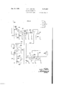
Where good quality three-element cable code signals are received over a cable the complete regeneration of the impulses is not necessary and the three-element cable code may be translated into a two-element code by means of the arrangement shown in Fig. 5. When the arrangement shown in this figure is used it will translate the slightly distorted three-element code which,
ence o9,
when finally re-translated into a two-element code, will be superior in quality to the threenent code received. A dot and a dash polar relay and i3! respond to the signals received over cable terminals 82 and 83. These relays control by means of their armatures 84 and 85 a tube 85 which, with its associated apparatus, controls in turn the conversion of the three-element into the two-element code. A relay 8'? connected with the plate 88 of tube 85 controls a so-called slave relay 89. A second .ium tube 99 with its plate relay 9| and assoed equipment are provided for the purpose i reducing the dash length signals received from into dot length signals. A tube 92 with its ate relay and associated timing circuits compensates for the characteristic distortion in the received signals.
e circuit of vacuum tube 86 is 50 arranged may be obtained, as well as the desired ratio or" the marking and spacing time controlled by this relay. These resistances may be adjusted to value of from O-100,000 ohms and are connccted in series to the positive pole of 110 volt generator 95. Midway between the two resistances is connected the positive pole over a condenser 9'I. The two resistances in series are connected also over a wire 98 with grid 99 of vacuum tube 86 through an intervening l-megohm resistance I00, and with one plate of condenser IOI, the other plate of which is connected to the positive pole over a 2500-ohm resistance I02. A second grid I03 of tube 88 and similar second grids of the two other tubes are connected to the positive pole over a 5000-ohm resistance I04. These second grids play no role in the functioning of these tubes and are illustrated merely because three-element tubes are not as easily available as double-grid tubes.
It will be seen, therefore, that space current can flow from cathode I05 (heated by a mament fed from a 26-volt source), to the plate 88 only when negative potential with which the condenser I0! is charged from the tongue of relay 8! has had time to leak off through resistances 94 and 95. When initially adjusting the circuit, these resistances are set so that the tube 86 will have a frequency in cycles per minute equal to the number of centerholes per minute of the received cable code signal, and the relay 8'! will have a one-third marking and a two-third spacing contact ratio.
The plate relay 93 associated with tube 92 controls the stopping of tube 85 from oscillating. The tube 8'3 is free to oscillate in the manner described under the control of resistances 94 and 95 only when relay 93 is de-energized and its armature is on the spacing contact. While the armature is on the marking contact, it connects the positive pole direct over resistance I00 with grid 99 and with the condenser NH. The change in the potential of grid 99 is controlled or timed not only when the grid is negative and approaching a positive condition, but also when it is positive and approaching a negative condition. If the grid potential were plotted against time, the resultant graph would have a saw-toothed appearance and the line going from negative to positive would have less slope than when going from positive to negative.
Assuming that the potential of condenser IOI is very positive with respect to the cathode I05, the grid 99 is positive and space current is flowing to plate 88. Relay 8'! is energized and negative potential is applied to the upper plate of condenser iilI over the armature and marking contact of relay 87, a 500 ohm resistance I65, variable resistance 94 and conductor 98. The time required for the charge will be dependent on the value of resistance 94.
When grid 99 finally becomes negative with respect to the cathode I05, the plate current will stop and the relay 81, becoming de-energized, will return its tongue to the spacing contact. A circuit will then immediately be closed from the negative pole through the tongue and spacing contact of relay 81, the winding of relay 89 shunted by a 400-ohm resistance and resistance 252 to the positive pole. The relay 89 becomes energized and the lower plate of condenser IDI, which was formerly positive, now suddenly becomes negative. The upper plate of the condenser also becomes very negative as a result of ings.
the changing of the potential of the lower plate. The grid 99 of the tube 86 is now very negative and the charge on condenser IOI leaks off through variable resistances 84 and 95 to the positive pole. After a certain length of time, depending on the combined resistances of 94 and 95, the grid will become positive with respect to the cathode and plate current will again flow, causing the reenergization of relay 8?. This relay breaks in its spacing contact the connection of the lower plate of condenser IilI to the negative pole which is now again connected only to the positive pole through the 2500-ohm resistance I02. The upper plate of the condenser is now very positive as a result of the change in potential of the lower plate, and the cycle of operation previously described is repeated.
This cyclic operation will continue as long as relay 83 is on its spacing contact. Resistance 94 is adjusted so that a length of time equal to onethird of a centerhole is required for the grid 99 to vary from positive to negative, and the resistance 95 is so adjusted that a length of time equal to two-thirds of a centerhole is required for the grid potential to vary from negative to .This plate current would be increasing while the armature was in transit between the contacts and thus the armature might never reach its back contact. Condenser 91 insures that the grid potential will continue in the negative direction at least until the armature of relay 81 reaches its back contact. When the armature reaches the back contact the grid becomes very negative. The l-megohm resistance I in series with the grid 89 reduces the grid current to a low value when the grid is positive.
The distortion suffered by the signals in their transmission through the cable is corrected by tube 82 and associated equipment.
In signals received over a long cable, the start of a cable code dot or dash which directly follows a spacing signal occurs relatively early as compared with the start of a dot directly following a dash or a dash directly following a dot. This is called the characteristic distortion of a cable code and the present circuit arrangement is arranged to compensate for it.
When no dot or dash signals are received the armatures 84 and 85 of relays 80 and 8| will be on their spacing contacts, as shown in the draw- The positive pole is, therefore, connected over a 3000-ohm resistance I01, armatures 85 and 84, and their spacing contacts, and a l-megohm resistance I08 to grid I09 of tube 92. Space current will, therefore, flow continuously from cathode IIO of the tube to plate III and maintain relay 98 energized. As above stated, while this relay 93 is energized, it maintains positive potential direct on the grid 98 of tube 86 and thus maintains relay 8? energized, preventing thus the cyclic operation of the tube. As soon as the first dot or dash is received, the positive pole through resistance i0] is disconnected in the contacts of relay 80 or 8I. The grid I09 of tube 92 will not immediately become negative, since it will take some time for the charge to leak off, variable condenser H2 being connected through a 10,000- ohm resistance II4 with resistance I08 and grid H2 and H4 are shunted by a 40,000-ohm resistance I I3. The greater the capacity of condenser II2, the longer will it take for the charge to leak off. When the grid I09 becomes negative with respect to cathode I I0, plate current will cease and the armature of relay 93 will leave its marking contact. The tube 88 will now start operating in the manner previously described to vibrate the armatures of relays 81 and 89 at centerhole speed. In response to each energization of relay 89, negative potential is applied through the armature and front contact of this relay, conductor H5 and resistance I08, to grid E09 of tube 92. This will prevent any clipping of the marks from relay 89 in case the received signal should be clipped, since the negative charge on grid I09 prevents the untimely energization of relay 93.
The amount of capacity in the variable condenser It? should be just sufiicient to lag the starting of the tube 86 by an interval of time equal to the characteristic distortion of the received signal. During the slight break in the cross-over of the received signal, both dot and dash relays 80 and BI will be resting their armatures on the spacing contacts for a moment. This cross-over will normally occur while the relay 89 is marking, whereby the grid I00 of tube 92 will be maintained at a negative potential over conductor II5. There will be, therefore, no tendency to check the oscillations of tube 86 during the signal cross-over. The arrival of a letter or word space will normally occur when the relay 89 is leaving its marking contact. The grid of 92 will quickly become positive and the oscillations will be checked.
The signals as repeated by relay 89 will, therefore, be of the proper length for the two-element dashes. Tube 90 and its associated relay SI and circuits reduce the dash length signals repeated by relay 89 into dot length signals for transmission over a land telegraph line I I6. The relay 9I may be energized by space current flowing from cathode II! of tube 90 to plate II8 of the tube while grid II9 is positive with respect to the cathode. The grid is connected over a l-megohm resistance I20 with a junction point I2I with which are connected:
(1) the positive pole in parallel over condenser I22 and over a 10,000-ohm resistance I23 and a resistance 124 which may be varied from 0 to 100,000 ohms;
(2) negative pole over the armature and back contact of relay 89 and a 500-ohm resistance I25; and
(3) the positive pole over the 3000-ohm resistance I01, the armature and marking contact of dash relay 8| and a conductor I26.
The resistance I24 is adjusted to delay the twoelement dot by one-third of a centerhole. If the received cable signal is a dash, then no delay is required. When the dash relay is operated it will apply positive potential over conductor R28 to grid II9 and cause immediately the energization of relay 9I, since as long as dash relay 8! is marking, the variable resistance PM is shunted by the comparatively low resistance I01.
While a double-throw switch I29 is in its normal or upper position, the positive pole of grounded battery I21 or the negative pole of grounded battery I2la will be applied to the telegraph line H8, depending whether the marking or spacing contact of relay SI is closed. In this case it is assumed that the land line is equipped with a polar line relay (see e. g., Fig. 6), and that the two-element code consists of positive impulses of one and two time unit duration to send dot and dash signals and of negative impulses to send ner:
First the output of relay 9| is connected by throwing switch I29 into the lower or testing position so that the percentage of marking of this relay is directly indicated on a milliammeter I28 and, at the same time, the marks are recorded on one pen of a double pen direct writer connected through a jack I30. The other pen of the direct writer should record the received cable signals.
The tongue of the dash relay BI is held to 1e marking contact and the beats of the translator are compared with received signals. The frequency is so adjusted that the beats on the tape are of the same frequency as the centerholes of the received signal. The adjustment for frequency is made by means of the variable resistances 94 and 95.
Adjustment for percentage marking on I28 is made by maintaining a suitable ratio between 94 and 95. This adjustment will be correct when the beats are of the same frequency as the incoming signals and 62 marking is indicated by meter I 28.
The dot relay tongue 84 is now held against its marking contact and the percentage marking is observed. The resistance I24 is adjusted so that the percentage marking be 33 The input of the translator is now connected to the received cable signals. All capacity is removed from condenser H2 and the distortion observed on the direct writer of the two-element output signals from the translator. The gap between the first dash and dot of the letter C will be slightly greater than between the second dash and dot. The capacity of condenser H2 is now slightly increased until there is no distortion on the letter C. The translator is now ready for operation.
Fig. 6 shows an arrangement for translating a two-element code into a three-element cable code direct writer record.
The direct writer diagrammatically indicated at 290 is provided in the plate circuit of a vacuum tube 20I and is shunted by a lOO-ohm resist ance 292 so that only a portion of the plate current passes through the coil of the direct writer. 1000- ohm resistances 203 and 204 are used as a voltage divider or potentiometer to apply a reduced voltage to plate 205 of tube 20I. The resistances in the plate circuit are so proportioned and arranged that when grid 206 of the tube is negative with respect to the cathode 23?, no plate current will flow and the pen of the direct writer 290 will not be deflected. This condition will be maintained when a dot received on telegraph line 208 is recorded. When the grid 296 is positive with respect to the cathode, maximum current will flow in the plate circuit and the pen of the direct writer will have maximum deflection. The direct writer is so connected that this deflection will be in the dash or downward direction of the tape. This condition is maintained while dashes are being recorded. In order to record spacing signals, it is necessary for the direct writer pen to assume a position midway between the dot line (zero plate current) and the dash line (maximum plate current). By maintaining grid 206 of tube 20I at a suitable potential with respect to the cathode, the direct writer pen will assume a position intermediate the dot and dash positions and thus record spacing.
Let us assume that a spacing signal is received on line 203. Grounded polarized line relay 209 remains de-energized with its tongue 2 I0 against the spacing contact, closing a circuit from the negative pole of volts generator 2I I, the windings of relays 2I2 and 2I3 in series, a 1500-ohm resistance 2I4 midway between the two generators 2 I I. Both relays become energized. When the line relay tongue 2I0 has remained away from its marking contact for a sufiicient length of time, grid 2I5 of a vacuum tube 2I6 becomes positive with respect to cathode 2|! of this tube. Space current will, therefore, flow from the cathode to plate 2I8, energizing relay 2I9. This relay will connect the negative pole over a 10,000-ohm resistance 220 and the center tap of the two generators 2 I I in parallel over a zero adjustment potentiometer 22I, conductor 222 and a 2.5 megohm resistance 223 to the grid 206 of tube MI. The potentiometer 22I is so adjusted that required grid potential is applied for permitting the flow of sufficient plate current in tube 20I for the direct pen writer to assume the abovementioned intermediate position.
Assuming that the next signal is a marking signal of dot duration, the line relay tongue 2I0 engages its marking contact and applies negative potential over a 200-ohm resistance 224 to grid 2I5 of tube 2I6 through an intervening 2.5-megohm resistance 225 and to a condenser 226. The other plate of the condenser is connected to the positive pole and the two plates are shunted by a variable resistance 221 and a fixed 10,000-ohm resistance 228. The condenser 226 will be quickly charged negatively as well as the grid 2I5, stopping the flow of plate current in tube 2I6 and de-energizing relay 2I9. The latter will disconnect the zero adjustment potentiometer 22I from grid 206 of tube 20I. will maintain the intermediate voltage on the grid 296 as long as required, provided that a high grid resistance of 2.5 megohms (223) is used. When the tongue 2I0 of the line relay 209 leaves its spacing contact, relays 2I2 and 2I3 become de-energized. When the tongue of relay 2I3 reaches its spacing contact, a circuit is closed from the positive pole through a variable resist ance 230, a 5000-ohm fixed resistance 23! and then in parallel over a 200-ohm resistance 232, a condenser 233 to the negative pole, and over the armature and back contact of relay 2I3 and a 200-ohm resistance 234 and condenser 235 to the negative pole. The charges of the two condensers 233 and 235 will mix and their voltages equalize. The capacity of condenser 235 is only a fraction of that of condenser 233, whereby the potential of the latter will be only slightly changed. Condensers 233 and 235 will now slowly take up a positive charge through the adjustable resistance 230. At the end of the marking period of line relay 209, the tongue 2I0 is again returned to the spacing contact and the relays 2I2 and 2I3 are re-energized. When relay 2I3 becomes energized, the condensers 233 and 235 will be separated and condenser 233 will be discharged. The energization of relay 2I2 will connect condenser 235 through its marking contact, a 200-ohm resistance 236, with condenser 229. Condenser 235 is much larger than condenser 229, whereby the potential of 235 will be A small grid condenser 229 only slightly altered when this circuit is estab- 15 lished. Condenser 229 will now be of the same potential as 235 and grid 206 of tube 2!!! will be of a similar potential.
If a dot signal is received, then condenser 229 wi l not have sufiicient charge to render grid 206 positive with respect to the cathode, whereby no plate current will flow to energize the direct writer The latter will record a dot.
If dash signal is received, then the line relay tongue rib is held against the marking contact for 'a sufiicient length of time for condenser 233 to receive a greater charge, whereby condensers i235 and 223 will have appreciably greater potential when relays 212 and M3 are re-energized upon the subsequent spacing of the line relay. ihe potential of 229 will now be suiiicient to render the grid positive with respect to the cathode whereby maximum plate current will how and the direct writer will record a dash. The variable resistance 22'! is so adjusted that if the line relay 2! does not mark for an interval of time equal to one centerhole, then the grid. 2E5 of tube 2E6 will become positive with respect to the cathode and suflicient plate current will flow to operate relay 2H3. When relay 2G9 becomes energized then, depending on the adjustment of potentiometer 22!, it will apply a potential on grid 296 of tube 28!, which will cause the recording of a spacing signal on the direct writer.
The correctness of the setting of dot-dash adjustment rheostat 23! will be indicated by the amplitude of the dashes on the direct writer 2013. Too little resistance will be indicated by dots of less than normal amplitude. The amount of resistance required to give an occasional dot of less than normal amplitude should be noted and the resistance at which dashes of less than full amplitude occur should also be noted. The rheostat 239 should be kept at an intermediate value.
The space adjustment rheostat 221 is regulated to make the dots or dashes preceding spaces of the proper length. The zero adjustment potentiometer 22! should be regulated to'make the zero line as indicated on the direct writer come midway between the dot and dash lines.
What is claimed is: 1. The method of electric telegraphy which comprises allotting to clot and dash signals preeasily legible two-element code may be transmitted.
2. In a telegraph transmitter for converting a three-element code into a two-element code, a source of current, a transmitting relay having a ontact connected with said source, a circuit for said relay, means responsive to the three-element code for controlling said circuit, and timing means for closing said circuit for two-thirds and opening it for one-third of a time unit when a dash signal occurs in the three-element code, and for closing the circuit for one-third and opening it for two-thirds of said time unit when a dot signal occurs in the three-element code.
3. In a telegraph transmitter for converting a three-element code into a two-element code, a source of current, a transmitting relay having an armature connected with the positive pole of said source, a circuit for said relay having two branches, a dash pecker actuated contact in the first and a dot pecker actuated contact in the second branch, two interrupters, and means for rotating said interrupters in unison, one of said interrupters marking for two-thirds and spacing for one-third of a revolution the first branch, and the other marking for one-third and spacing for two-thirds of a revolution the second branch of the relay circuit.
a. In a telegraph circuit for translating a code composed of a certain number of elements into a code composed of a different number of elements, a relay associated with the input and a relay associated with the output end of said circuit, means including a vacuum tube having a grid electrode for controlling the operation of the output relay in accordance with the operation of the input relay, and means for performing said translation including a variable grid leak reactance for timing the operation of said vacuum tube.
5. In a telegraph circuit for translating a code composed of a plurality of elements into a code composed of a different number of elements, an impulse receiving relay, a timing circuit for distinguishing between dots and dashes received by the marking time of said relay, transmitting relay mechanism variably responsive to said timing circuit, and a second timing circuit to space the operation of said transmitting relay mechanism when said receiving relay does not mark for a predetermined length of time.
6.1'n a telegraph circuit for translating a two-element code into a three-element code, a neutral relay responsive to all marking and spacing impulses, a timing circuit for distinguishing dots and dashes by the marking time of said relay, dot and dash transmitting relays variably responsive to said timing circuit, and a second timing circuit to space said dot and dash transmitting relays when said neutral relay does not for a predetermined length of time.
'7. In combination, a source of current, a neutral telegraph line relay having an armature connected with the negative pole of said source, a first and a second vacuum tube each having a cathode, a grid and an anode, a first relay having an armature connected with the positive pole and a winding connected between the positive pole and the anode of the first tube, a second relay having two windings one of which is connected between the positive pole and the anode of the second tube, a connection from the positive pole to the grid of each tube, each including a condenser and a variable resistance in parallel, a connection from the marking contact of said line relay to the grid of the first tube, a control relay, a connection from the spacing contact of said line relay in parallel to the winding of the control relay and the armature of said second relay, a connection from the negative pole to the grid of the second tube including the marking contact of the control relay, polarized dot and dash transmitting relays having windings controlled solely in the marking contact of said first relay, second windings for said polarized relays jointly controlled in the spacing contacts of said first, second and line relays, third windings for said polarized relays, and a circuit for said third windings including in series the marking contacts oi the line and first relays, and the marking contact and the second winding of the second relay.
8. In a telegraph circuit for regenerating cable code signals composed of a certain number of elements and translating them into a code composed of a different number of elements, dot and dash relays responsive to incoming code signals, a tuning fork, a time delay circuit jointly controlled by the tuning fork and contacts of said dot and dash relays, and a code transmitting relay controlled by said time delay circuit.
9. In a telegraph circuit for regenerating threeelement cable code signals and translating them into a two-element code, neutral dot and dash relays responsive to incoming three-element cable code signals, a tuning fork having a contact closed only while one of said relays is moving its armature, a time delay circuit including a vacuum tube having a grid jointly controlled by the tuning fork contact and the armatures of said dot and dash relays, and a two-element code transmitting relay in the output circuit of said tube.
10. In a telegraph system, a cable code signal regenerator having a tuning fork and two output terminals, a source of current, a neutral dot relay connected with one and a neutral dash relay with the other terminal, a vacuum tube having a cathode, a grid and an anode, a neutral transmitting relay connected with the anode, a con nection between the grid and the positive pole of said source including a relatively low resistance and a condenser in series, a second connection between the grid and the positive pole including a low resistance and a make contact of the dash relay in series, a third connection between the grid and the positive pole including in series a low resistance, a make contact of the dot relay and a variable resistance, and a connection between the grid and the negative pole including a contact closed by said tuning fork approximately for one-third of its operating time.
11. In a telegraph circuit for translating a cable of one type into a code of a difierent type, relay mechanism responsive to dot and dash signals received, means including a vacuum tube controlled by said relay mechanism for converting the code or" one type into a code of the different type, means including a second vacuum tube controlled by the output of the first tube for reducing dash length signals received from the first tube into dot length signals, and a timing circuit including a third vacuum tube to compensate for the characteristic distortion in the received three-element signals.
12. In a telegraph circuit for translating a three-element cable code into a two-element code, dot and dash polar relays responsive to signals received, means including a vacuum tube controlled by said relays for converting the three-element code into a two-element code, a slave relay controlled by the output of said tube, means including a second vacuum tube controlled by said relay for reducing dash length signals received from the first tube into dot length signals, and a timing circuit including a vacuum tube to compensate for the characteristic distortion in the received three-element signals.
13. In a telegraph circuit for converting a three-element cable code into a two-element code, a source of current, means including a vacuum tube having a cathode, an anode and a grid, a grid circuit for said tube connected with a low capacitance grid leak, a relay in the output circuit of said tube controlling the two-element code output, means including two variable resistances and in parallel with the resistance, a device controlled by the three-element signals received for applying to the grid circuit positive potential, a relatively high capacitance connecting the positive pole to a point midway between the two variable resistances, means controlled by said relay for applying negative potential to said grid over one of said variable resistances, and a connection from the negative pole to said relatively low capacitance controlled by said relay.
14. In a telegraph circuit to compensate for the distortion suffered by incoming signals, polarized dot and dash relays responsive to incoming signals, a vacuum tube having a cathode, a grid and an anode, a source of current, a grid circuit including a high resistance, the spacing contacts of said relays and a lower resistance in series to the positive pole, a relay in the anode circuit, impulse sending means operable in accordance with the incoming signals, means to prevent the operation of said impulse sending means while the anode relay is energized and for operating it when the anode relay is de-energized, a marking contact in the impulse sending means for connecting the negative pole to said high resistance, a leakage path from said grid to the negative pole in cluding in series a resistance, and a variable condenser and an intermediate resistance in parallel with the last mentioned resistance and condenser, the capacitance of said condenser being just sufficient to lag the de-energization of the anode relay by an interval of time equal to the characteristic distortion or the incoming signals.
15. In a telegraph system, input relay mechanism, three vacuum tubes each having a cathode, a grid and an anode, a relay connected with the anode of each tube, the anode relay of the third tube controlling the output of the system, a source of current, a slave relay controlled by the anode relay of the second tube, a variable capacitance, means jointly controlled by said capacitance, relay mechanism and slave relay for varying the potential on the first tube grid, a variable resistance, means jointly controlled by the variable resistance and the anode relays of the first and second tubes for varying the potential on the second tube grid, another variable resistance, and means jointly controlled by the last mentioned resistance, said slave relay and said relay mechanism for varying the potential on the third tube grid.
16. In a telegraph system, polarized dot and dash input relays, three vacuum tubes each having a cathode, a grid and an anode, a relay connected with the anode of each tube, a source 01" current, a connection between the grid of the first tube and the negative pole including a resistance and in parallel therewith, a resistance and a variable condenser, and a second parallel connection to the positive pole including spacing contacts of said input relays and a resistance in series, parallel paths between the grid of the second tube and the positive pole, the first including a condenser and resistance in series, the second marking contact of the anode relay of the first tube, the third two variable resistances in series, and the fourth one of said variable resistances and a condenser, two paths between the negative pole and the grid of the second tube, one including the marking contact of the anode relay oi the second tube a resistance and said one of said variable resistances in series, and the other the spacing contact of said anode relay of the second tube, a slave relay and the condenser in the first path to the positive pole, two parallel paths between the grid of the third tube and the positive pole, one including in series a make contact of said dash relay and the resistance in the second parallel path to the grid of the first tube, and the other a condenser and a variable resistance in parallel, a path between the negative pole and the grid of the third tube including a resistance and the spacing contact of said slave relay, and a path between the grid of the first tube and the negative pole including a make contact of said slave relay.
17 In a telegraph circuit, a source of current, a line relay responsive to two-element code signals, a direct writer for recording said signals in a three-element code, a vacuum tube having a cathode, a grid and an anode, means controlled by the incoming dot and dash signals for applying negative, positive and an intermediate potential to the grid, and an anode including said direct writer.
18. In a telegraph circuit, a source of current, means responsive to input signals in a certain code, a device in the output of said circuit operable in a different code, a vacuum tube having an anode, a cathode, and a grid, means controlled by the input signals for applying negative, positive and an intermediate potential to said grid, and an anode circuit including said device.
19. In a telegraph circuit, a source of current, a line relay responsive to two-element code signals, a direct writer for recording said signals in a three-element code, a vacuum tube having a cathode, a grid and an anode, means controlled by the incoming dot and dash signals for varying from negative to positive the potential on the grid, means responsive to incoming spacing signals for maintaining said grid at potential intermediate said negative and positive potentials, an anode circuit including said direct writer, and means for so proportioning said anode circuit that when the grid is negative no current will flow through the direct writer to deflect it, when the grid is positive maximum current will fiow through the anode circuit causing maximum defiection of the direct writer, and when the grid is at the intermediate potential enough current flows in the anode circuit to deflect the direct writer into a position intermediate zero and maximum deflection.
20. In a telegraph system, a grounded polar line relay, a source of current, two vacuum tubes each having a cathode, a grid and an anode, a relay connected with the anode of the first tube, a direct writer connected with the anode of the second tube, two neutral relays in series with the spacing contact of said line relay, a very high resistance connected with the grid of each tube, two parallel branches from the very high resistance oi the first tube grid to the positive pole, one including a high capacitance and the other a variable resistance, a path from the very high resistance of the first tube grid to the negative pole including the marking contact of the line relay and a very low resistance in series, parallel paths from the very high resistance of the second tube grid over a very low capacitance to the negative pole, to the armature of the first tube anode relay, and over a very low resistance to the marking contact of the first neutral relay, a potentiometer connected over a very high resistance between the negative pole and the marking contact of the first tube anode relay, a path from the armature of the first neutral relay over a very low resistance and a low capacitance to the negative pole and another path over the spacing contact and armature of the second neutral relay and then over a very low resistance and a very high capacitance to the negative pole and in parallel over a high and a variable resistance to the positive pole, the marking contact of the second neutral relay being connected to the negative pole, and a potentiometer in the anode circuit of the second tube.
21. The method of electric telegraphy which comprises allotting to dot, dash and space signals predetermined periods of time, of the same length for each kind of signal, sending the dash signal only during the first and second one-third portions of a period, sending the dot only during the second one-third portion of a period, and sending the space signal during the entire period, whereby an easily legible two-element code may be transmitted.
22. The method of electric telegraphy which comprises allotting to dot, dash and space signals predetermined periods of time, of the same length for each kind of signals, during the sending of a dot spacing the line for the first one-third of the period, marking it for the second one-third and spacing it for the third one-third, during the sending of a dash signal marking the line during the first and second one-third of a period and spacing it for the third one-third of the period, and for the sending of a spacing signal spacing the line for an entire period.
23. In a telegraph transmitter for converting a three-element code into a two-element code, a source of current, a transmitting relay having an armature connected with said source, a circuit for said relay having two branches, a contact operable in accordance with the dash signals of the three-element code in the first and a contact operable in accordance with the dot signals of the three-element code in the second branch, two interrupters, and means for rotating said interrupters in unison, one of said interrupters marking for two-thirds and spacing for one-third of a revolution the first branch, and the other marking for one-third and spacing for two-thirds of a revolution the second branch of the relay circuit.
24. A telegraph circuit according to claim 4 and comprising a second vacuum tube having a variable grid leak reactance and cooperating in the control of the output relay, and means controlled by the input relay for alternately applying negative potential to the grids of said tubes.
25. In a telegraph circuit for translating 2. code composed of a plurality of elements into a code composed of a different number of elements, a relay responsive to impulses received, a timing circuit including a vacuum tube for distinguishing between dots and dashes received by the marking time of said relay, transmitting relay mechanism variably controlled by said vacuum tube, and a second timing circuit including a second vacuum tube to space the operation of said transmitting relay mechanism when said relay does not mark for a predetermined length of time.
26. In combination, a source of current, a telegraph line relay, a first and a second vacuum tube each having a cathode, a grid and an anode, a first relay connected with the anode of the first tube, a second relay connected with the anode of the second tube, a grid leak condenser for each tube, a variable resistance in parallel with each grid leak condenser, means controlled by said line relay for applying negative potential to the grids of said tubes, dot and dash transmitting relay mechanism, a circuit for said relay mechanism controlled by said first relay, a circuit for said relay mechanism jointly controlled by said first, second and line relays, and a third circuit for said relay mechanism jointly controlled by the line, first and second relays.
27. In combination, a source of current, a neutral telegraph line relay, a first and a second vacuum tube each having a cathode, a grid and an anode, a first relay connected with the anode of the first tube, a second relay having two windings one of which is connected with the anode of the second tube, a connection from the positive pole to the grid of each tube, each including a capacitance and a variable resistance in parallel, means operable upon the marking of said line r lay for applying negative potential to the grid of the first tube, a control relay controlled in the spacing contact of said line relay, a connection from the negative pole to the grid of the second tube including the marking contact of the control relay, polarized dot and dash transmitting relays having windings controlled in the marking contact of said first relay, second windings for said polarized relays jointly controlled in the spacing contacts of said first, second and line relays, third windings for said polarized relays, and a circuit for said third windings including in series the marking contacts of the line and first relays, and the marking contact and a holding winding of the second relay.
28. In a telegraph circuit for regenerating three-element cable code signals and translating them into a two-element code, neutral dot and dash relays responsive to incoming three-element cable code signals, a tuning fork having a contact closed only while one of said relays is moving its armature, a time delay circuit jointly controlled by the tuning fork contact and the armatures of said dot and dash relays, and a twoelement code transmitting relay in said time delay circuit.
29. In a telegraph system, a cable code signal regenerator having a tuning fork and two output terminals, a source of current, a neutral dot relay connected with one and a neutral dash relay with the other terminal, a vacuum tube having a cathode, a grid and an anode, a neutral transmitting relay connected with the anode, a grid leak path including a condenser for said tube, a second grid leak path including a low resistance and a make contact of the dash relay, a third grid leak path including a low resistance, a make contact of the dot relay and a variable resistance, and a connection between the grid and the negative pole including a contact controlled by said tuning fork.
30. A telegraph circuit according to claim 11 and in which two variable resistances are connected in series with the grid of the first vacuum tube controlling the frequency of operation of the tube in accordance with the frequency of the code signals received, and a relay in the output of the first tube having a one-third marking and two-third spacing contact ratio.
31. A telegraph circuit according to claim 11 and a relay controlled by the output of the first tube and having a two-thirds marking and onethird spacing contact ratio.
32. A telegraph circuit according to claim 11 and in which a relay is operated by the output of said third tube, and means controlled by the last mentioned relay for stopping the operation of said first tube.
33. A telegraph circuit according to claim 11, means for alternately applying positive and negative potentials to the grid of the first tube, means including a variable resistance for timing the change of potential on said grid from negative to positive to take place at a certain rate, and means including the output circuit of the first tube and one of said variable resistances for timing the change of potential from positive to negative at a faster rate.
34. A telegraph circuit according to claim 11, means for alternately applying positive and negative potentials to the grid of the first tube, and means including variable resistances for varying the potential on said grid twice as fast from positive to negative as form negative to positive.
35. A telegraph circuit according to claim 12 and in which two variable resistances are connected in series with the grid of the first vacuum tube controlling the frequency of operation of the tube in accordance with the frequency of the three-element code signals received, a relay in the output of the first tube having a one-third marking and two-thirds spacing contact ratio and controlling said slave relay.
36. A telegraph circuit according to claim 12, means including the second tube and variable resistances for alternately applying positive and negative potentials to the grid of the first tube, means including said variable resistances for timing the change of potential on said grid from negative to positive to take place at a certain rate, and means including the ouput circuit of the first tube and one of said variable resistances for timing the change of potential from positive to negative at a faster rate.
37. A telegraph circuit according to claim 12, means including the second tube and variable resistances ior alternately applying positive and negative potentials to the grid of the first tube, means including said variable resistances for timing the change of potential on said grid from negative to positive to take place at a certain rate, means including the output circuit of the first tube and one of said variable resistances for timing the change of potential from positive to negative at a faster rate, and means controlled by said slave relay and said dot and dash relays for variably applying positive and negative potentials to the grid of said third tube.
38. In a telegraph circuit for converting a three-element cable code into a two-element code, a source of current, means including a vacuum tube having a cathode, an anode and a grid, a grid circuit for said tube including a high resistance and controlled by the three-element signals received, a relay in the output circuit of said tube controlling the two-element code output, two branch paths for said grid circuit to the positive pole of said source, one including two variable resistances in series, and the other a relatively low capacitance, a path from the positive pole through a relatively high capacitance to a point in said one of said branch paths midway between the two variable resistances, a connection from said point to the negative pole including a low resistance and the marking contact and armature of said relay, and a connection from the negative pole to said relatively low capacitance including the armature and spacing contact of said relay.
39. In a telegraph circuit to compensate for the distortion suffered by incoming signals, relay mechanism responsive to incoming signals, a vacuum tube having a cathode, .a grid and an anode, a source of current, a relay in the anode circuit, impulse sending means operable in accordance with the incoming signals and controlled by said relay, means controlled by the impulse sending means and said relay mechanism for varying the potential on said grid, and a leakage path for said grid to lag the deenergization of the anode relay by an interval or" time equal to the characteristic distortion of the incoming signals.
40. In a telegraph circuit to compensate for the distortion suffered by incomng signals, relay mechansm responsive to incoming signals, a vacuum tube having a cathode, a grid and an anode, a source of current, means including said relay mechanism for applying positive potential to the grid, a relay in the anode circuit, impulse sending means operable in accordance with the incoming signals and controlled by the anode relay, a marking contact in the impulse sending means for applying negative potential to said grid, a leakage path from said grid to the negative pole including a capacitance just sufficient to lag the operation of the anode relay by an interval of time equal to the characteristic distortion of the incoming signals.
41. A telegraph circuit according to clam 17, and a potentiometer in the anode circuit.
42. A telegraph circuit according to claim 1'7, and a potentiometer controlling the circuit of said grid.
43. A telegraph circuit according to claim 18, and a potentiometer in the output circuit.
44. A telegraph circuit according to claim 18, and a potentiometer in the circuit of said grid.
45. A telegraph circuit according to claim 18, a low capacitance grid leak condenser, a high capacitance condenser, and means controlled by the input signals for interconnecting said condensers.
46. In a telegraph circuit, a source of current, a polar line relay responsive to two-element code signals, a direct writer for recording said signals in a three-element code, a Vacuum tube having a cathode, a grid and an anode, means including said relay and controlled by the incoming dot and dash signals for applying negative and positive potentials to the grid, means including said relay and responsive to incoming spacing signals for maintaining said grid at potential intermediate said negative and positive potentials, and an anode circuit including a resistance, a potentiometer and said direct writer, said anode circuit eing so proportioned and adjusted that when the grid is negative no current will flow through the direct writer to deflect it, when the grid is positive maximum current will fiow through the anode circuit causing maximum deflection of the direct writer, and when the grid is at the intermediate potential enough current fiows in the anode circuit to deflect the direct writer into a position intermediate zero and maximum deflection.
4'7. In a telegraph system, a line relay, a source of current, two vacuum tubes each having a cathode, a grid and an anode, a relay connected with the anode of the first tube, a direct writer and a potentiometer connected with the anode of the second tube, two neutral relays in series with the spacing contact of said line relay, a
very high resistance connected with the grid of each tube, two parallel branches from the very high resistance of the first tube grid to the positive pole including, respectively, a capacitance and a variable resistance, a path from the very high resistance of the first tube grid to the negative pole including the marking contact of the line relay, a path from the very high resistance of the second tube grid over a very low capacitance to the negative pole, another path from the last mentioned resistance to the negative pole controlled by the first tube anode relay and another potentiometer, a third path from the last mentioned resistance to the negative pole including a low capacitance and controlled by the first neutral relay, means controlled by the second neutral relay for connecting the last mentioned path over a very high capacitance to the negative pole, and a variable resistance connected with the positive pole and in parallel with the last mentioned very high capacitance.
48. A telegraph system comprising means for sending a dash signal only during the first and second one-third portions of a period and means for sending a dot signal only during the second one-third portion of a period.
49. A telegraph system comprising means for translating standard three element code signals into two element code signals in which the dot and dash signals each are allotted equal perods of time, means for transmitting said two ele ment code signals, and translating means operative in response to said transmitted two element code signals for retranslating said two element code into a three element code.
50. A telegraph system comprising means for sending a dash signal only during the first and second one-third portions of a period, means for sending a dot signal only during the second onethird portion of an equal period, and means responsive to said dash and dot signals for translating said signals into code elements comprising positive and negative impulses, of equal time duration.
51. A telegraph system for converting a three element code into a. two element code, and reconverting said two element code into a three element code comprising a source of current, a transmitting relay having a contact connected with said source, a circuit responsive to the three element code for controlling said circuit, timing means for closing said circuit for two-thirds and opening it for one-third of a time unit when a dash signal occurs, and for closing said circuit for one-third and openng it for two-thirds of said time unit when a dot signal occurs in said three element code to transmit a two element code, an impulse receiving relay in said circuit, a timing means for distinguishing between dot and dash signals of said two element code by the marking time of said receiving relay, and a transmitting relay means variably responsive to said timing circuit.
ALDER F. CONNERY.
Priority Applications (1)
| Application Number | Priority Date | Filing Date | Title |
|---|---|---|---|
| US25051A US2141237A (en) | 1935-06-05 | 1935-06-05 | Electric telegraphy |
Applications Claiming Priority (1)
| Application Number | Priority Date | Filing Date | Title |
|---|---|---|---|
| US25051A US2141237A (en) | 1935-06-05 | 1935-06-05 | Electric telegraphy |
Publications (1)
| Publication Number | Publication Date |
|---|---|
| US2141237A true US2141237A (en) | 1938-12-27 |
Family
ID=21823781
Family Applications (1)
| Application Number | Title | Priority Date | Filing Date |
|---|---|---|---|
| US25051A Expired - Lifetime US2141237A (en) | 1935-06-05 | 1935-06-05 | Electric telegraphy |
Country Status (1)
| Country | Link |
|---|---|
| US (1) | US2141237A (en) |
Cited By (7)
| Publication number | Priority date | Publication date | Assignee | Title |
|---|---|---|---|---|
| US2436441A (en) * | 1945-02-22 | 1948-02-24 | Rca Corp | Printer for morse code signals |
| US2480386A (en) * | 1947-04-09 | 1949-08-30 | Rca Corp | Transcriber for ink recorder tape |
| US2560434A (en) * | 1948-07-27 | 1951-07-10 | Gloess Paul Francois Marie | Device for translating duration or time modulated pulses into coded pulses |
| US2579469A (en) * | 1939-03-24 | 1951-12-25 | Int Standard Electric Corp | Revertive calling party line system |
| US2700696A (en) * | 1950-06-16 | 1955-01-25 | Nat Res Dev | Electrical signaling and/or amplifying systems |
| US2865018A (en) * | 1954-06-25 | 1958-12-16 | Raytheon Mfg Co | Intelligence transmission |
| US3214749A (en) * | 1959-11-23 | 1965-10-26 | Bell Telephone Labor Inc | Three-level binary code transmission |
-
1935
- 1935-06-05 US US25051A patent/US2141237A/en not_active Expired - Lifetime
Cited By (7)
| Publication number | Priority date | Publication date | Assignee | Title |
|---|---|---|---|---|
| US2579469A (en) * | 1939-03-24 | 1951-12-25 | Int Standard Electric Corp | Revertive calling party line system |
| US2436441A (en) * | 1945-02-22 | 1948-02-24 | Rca Corp | Printer for morse code signals |
| US2480386A (en) * | 1947-04-09 | 1949-08-30 | Rca Corp | Transcriber for ink recorder tape |
| US2560434A (en) * | 1948-07-27 | 1951-07-10 | Gloess Paul Francois Marie | Device for translating duration or time modulated pulses into coded pulses |
| US2700696A (en) * | 1950-06-16 | 1955-01-25 | Nat Res Dev | Electrical signaling and/or amplifying systems |
| US2865018A (en) * | 1954-06-25 | 1958-12-16 | Raytheon Mfg Co | Intelligence transmission |
| US3214749A (en) * | 1959-11-23 | 1965-10-26 | Bell Telephone Labor Inc | Three-level binary code transmission |
Similar Documents
| Publication | Publication Date | Title |
|---|---|---|
| US2365450A (en) | Radio telegraph multiplex system | |
| GB837670A (en) | Improvements in or relating to signal transmission systems | |
| US2141237A (en) | Electric telegraphy | |
| US2292404A (en) | Collateral control by tape slack | |
| US2321618A (en) | Space discharge oscillating relay | |
| US2676204A (en) | Pulse demodulating circuit | |
| US2462613A (en) | Communication system | |
| US1717624A (en) | Amplification and reproduction of electrical impulses | |
| US2495946A (en) | Synchronizing corrector circuit | |
| US1771446A (en) | Regenerative telegraph repeater | |
| US2658944A (en) | Telegraph signal regenerator apparatus | |
| US2154608A (en) | Regenerative telegraph repeater | |
| US2802052A (en) | Regenerative telegraph repeaters | |
| US2375044A (en) | Selecting system | |
| US2816956A (en) | Electronic regenerative repeater | |
| US2351684A (en) | Electric remote-control system | |
| US2509829A (en) | Duplex telegraph system | |
| US1929879A (en) | Telegraph correction system | |
| US1770485A (en) | Means for neutralizing disturbances, especially of telegraph signals transmitted by radio | |
| US1832308A (en) | Interpolating system | |
| US1601940A (en) | Telegraph system | |
| US2183708A (en) | Signaling system | |
| US1855244A (en) | Telegraph system | |
| US1875935A (en) | Dot insertion | |
| US2619541A (en) | System for receiving messages transmitted electrically |