US2139883A - Maize header - Google Patents
Maize header Download PDFInfo
- Publication number
- US2139883A US2139883A US162053A US16205337A US2139883A US 2139883 A US2139883 A US 2139883A US 162053 A US162053 A US 162053A US 16205337 A US16205337 A US 16205337A US 2139883 A US2139883 A US 2139883A
- Authority
- US
- United States
- Prior art keywords
- grain
- members
- machine
- heads
- spaced
- Prior art date
- Legal status (The legal status is an assumption and is not a legal conclusion. Google has not performed a legal analysis and makes no representation as to the accuracy of the status listed.)
- Expired - Lifetime
Links
- 240000008042 Zea mays Species 0.000 title description 4
- 235000016383 Zea mays subsp huehuetenangensis Nutrition 0.000 title description 4
- 235000002017 Zea mays subsp mays Nutrition 0.000 title description 4
- 235000009973 maize Nutrition 0.000 title description 4
- 235000013339 cereals Nutrition 0.000 description 34
- 238000003306 harvesting Methods 0.000 description 8
- 238000010276 construction Methods 0.000 description 2
- 235000021438 curry Nutrition 0.000 description 2
- 240000006394 Sorghum bicolor Species 0.000 description 1
- 235000011684 Sorghum saccharatum Nutrition 0.000 description 1
- 238000005452 bending Methods 0.000 description 1
Images


Classifications
-
- A—HUMAN NECESSITIES
- A01—AGRICULTURE; FORESTRY; ANIMAL HUSBANDRY; HUNTING; TRAPPING; FISHING
- A01D—HARVESTING; MOWING
- A01D45/00—Harvesting of standing crops
- A01D45/02—Harvesting of standing crops of maize, i.e. kernel harvesting
- A01D45/021—Cornheaders
Definitions
- a still further object of the invention is to provide means for catching the heads of grain after they have been cut, toy insure, against the grain heads falling through the machine to the ground surface.
- Figure 4 is a bottom plan View of one of the harvesting sections.
- the machine embodies a pair of harvesting sections, indicated generally by the reference character 5, the sections being mounted on the usual tractor, and spaced apart in such a manner that two rows of grain may be harvested simultaneously.
Landscapes
- Life Sciences & Earth Sciences (AREA)
- Environmental Sciences (AREA)
- Outside Dividers And Delivering Mechanisms For Harvesters (AREA)
Description
W. CURRY MAIZE H EADER Dec. 113, `1938.
Filed Sept. 1, 1937 3 Sheets-Sheet 1 A NN ATTORNEYS.
Dec. 13, 1938. u W. CURRY 2,139,883
MAI ZE HEADER Filed Sept. l, 1937 3 Sheets-Sheet 2 ATTORNEYS.
Dec. 13, 1938.
.w. cURRY l MAIZE HEADER Filed Sept.*1, 1937 3 Sheets-Sheet 3 A TTORNEYS.
Patented Dec. 13, 1938 UNITED STATES PATENTOFFICE MAIZE HEADER Wiley Curry, Tahoka, Tex. Application September 1, 193.7, Serial No. 162,653
4 Claims.
This invention relates to agricultural machines, and particularly to agricultural machines designed primarily for harvesting grain such as maize, sorghum o-r the like, which is planted in rows, an important object of the invention being to provide a device ofthis character which will cut the grain heads from the stalks, and convey the heads to the rear of the machine, to a place of deposit.
Another object of the invention is the provision of means whereby the entire heads of the grain will be cut, regardless of the lengths of the heads.
A still further object of the invention is to provide means for catching the heads of grain after they have been cut, toy insure, against the grain heads falling through the machine to the ground surface.
With the foregoing and other objects in view, which will appear as the description proceeds, the invention resides in the combination and arrangement of parts and in the details of construction hereinafter described and claimed, it being understood that changes in the precise em,- bodiment of the invention herein described, may be made within the scope of what is claimed, without departing from the spirit of the invention.
Referring to the drawings:
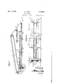
Figure 1 is a plan View of a harvesting machine constructed in accordance with the invention.
Figure 2 is a side elevational View thereof.
Figure 31s a longitudinal sectional view through one of the harvesting sections of the machine.
Figure 4 is a bottom plan View of one of the harvesting sections.
Figure 5 is a sectional view taken on line 5-5 of Figure 2 of ,the drawings.
Figure 6 is a sectional view taken on line 6-6 of Figure 2.
Referring to the drawings in detail, the machine embodies a pair of harvesting sections, indicated generally by the reference character 5, the sections being mounted on the usual tractor, and spaced apart in such a manner that two rows of grain may be harvested simultaneously.
In view of the fact that the harvesting sections are identical in construction, only one harvesting section will be described in detail.
Each harvesting section comprises substantially long members 6 spaced apart, as clearly shown by the drawings. These members 6 have their rear ends supported on the main aXle 'I of the tractor, which is indicated by the reference character 8, the forward ends of the members 6 being supported by means of the rod 9, that is secured to the forward end of the tractor.
The bracket Il'I which connects the members 6 at the rear endsl thereof, also provides a support for the power shaft I I that receives rotary motion L from the shaft I2 of the tractor, through the medium of the beltIS. Y
Extending upwardly from the members 6, and; arranged along the inner longitudinal edges thereof, are substantially wide members I4, between which the endless conveyor I5 operates, the endless conveyor being of a width to extend across the space between the members I4. The members` I4 are` constructed to provide wide forward ends and narrow rear ends, with the result that the endless carrier I5,vwh ichv operates in parallel relation with the upper edges of the members I4, moves in an inclined plane, the forward end of the carrier I5 being an. appreciable distance above the rear end thereof, with the result that the grain engaged by the lugs` I6 of the carrier I5, will be gradually bent rearwardly, as the grain heads are carried into the machine to the cutters, to be hereinafter more fully described. In order that the grain will be directed inwardly to the center of the machine, the forward inner ends of the members 6 are beveled as at I'I. Vertical shafts I8 are mounted in bearings I9 secured to the outer surfaces of the members I4 near the forward end of the machine, which shafts support the disk-like blades 20 that are of diameters` to overlap each other to the end that grain stalksr fed into the machine will be cut as the blades rotate. At the rear end of the machine are vertical shafts 2I that operate in bearings 22, the shafts 2| providing supports for the disk-like blades 23 that operate in a plane above the blades 20. Sprockets 24 are secured to the shafts I8 f and 2 I, over which the endless chains 25 operate, there being provided openings in the members I4 through which the chains 25 operate so that the lugs 26 extending therefrom will contact the grain to draw the grain into the machine. These chains also operate to transmit rotary movement of the shafts 2|, which carry pinions 2'I at their lower ends meshing with pinions 28 secured to the power shaft II, to the shafts I8. Operating in parallel relation with the chains 25 directly below the chains 25, are chains 29 that move over sprockets 3U mounted on the shafts 2 I, at the rear of the machine, and over the shafts 32 supported at the forward end of the machine. Lugs 33 extend inwardly from the chains to Contact with the grain tol move the grain into the machine.
Sprockets 34 are mounted near the upper ends of the shafts I8 and operate the substantially short chains 35 that move over sprockets 36 mounted on shafts 31, that in turn operate in the bearings 38, secured to the membersr I4. These chains 35 are also provided with horizontal lugs 39 that engage the longer stalks of grain to carry them into the machine.
Disposed at the rear end of each section of the machine, is a pipe 40, through which the heads of grain cut, are fed to the endless convepor 40 operating in the tubular housing 42, where the heads of grain are carried to a place of deposit. The endless conveyor 4I is operatedby the chain 43 moving over the sprocket 44 mounted on the shaft I l and sprocket 45 mounted on the endless conveyor shaft 46.
Near the central portion of each section is a vconnecting bar 41, which holds the members 6 in proper spaced relation with each other, and at the same time provide a support for the forward endsof the spaced rods 48 that extend along the bottom of each section at points within the space between the members 6, supporting the heads of grain which would otherwise fall to the ground surface.
I claim:
1. In a grain harvester, a body portion including spaced members, superimposed endless conveyors operating in horizontal spaced relation with respect to each other, a substantially shortv endless conveyor disposed adjacent to the forward end of the spaced members, and operating above the first mentioned conveyors, and an inclined endless conveyor of a width equal to the width of the space between the spaced members and adapted to engage the heads of the grain being cut andV gradually bend the grain downwardly, and knives for cutting the heads from r the stalks of the grain.
2. In a grain harvester, a body portion comprising parallel spaced members, upper and lower endless conveyors operating between the spaced members vadjacent to the lower edges of the spaced members, front and rear knives mounted on said spaced members, an endless conveyor operating in a plane inclined downwardly from the forward end of the spaced members and above the rst mentioned endless conveyors, the latter endless conveyor adapted to feed the grain to the knives.
3. In a grain harvester, a body portion including parallel spaced members, spaced endless conveyors operating adjacent to the lower edges of the spaced members and adapted to feed grain between said members, blades operating adjacent to the forward ends of said spaced members and adapted to cut the standing grain near the bases of the stalks thereof, blades operating adjacent to the rear ends of said spaced members, said conveyors adapted to feed grain into the latter blades to be cut from the stalks, and means for conveying the heads of the grain from the latter knives.
4. In a grain harvester, a pair of longitudinally spaced members, endless conveyors supported by the spaced members, lugs extending inwardly from the spaced members and adapted to engage the stalks of the grain moving the stalks rearwardly, knives adapted to cut the grain stalks at the bases thereof, knives operating adjacent to the rear ends of the spaced members, and a conveyor operating in an inclined plane above the knives for bending the grain stalks rearwardly and feeding the heads of the grain to the latter knives.
WILEY CURRY.
Priority Applications (1)
| Application Number | Priority Date | Filing Date | Title |
|---|---|---|---|
| US162053A US2139883A (en) | 1937-09-01 | 1937-09-01 | Maize header |
Applications Claiming Priority (1)
| Application Number | Priority Date | Filing Date | Title |
|---|---|---|---|
| US162053A US2139883A (en) | 1937-09-01 | 1937-09-01 | Maize header |
Publications (1)
| Publication Number | Publication Date |
|---|---|
| US2139883A true US2139883A (en) | 1938-12-13 |
Family
ID=22583968
Family Applications (1)
| Application Number | Title | Priority Date | Filing Date |
|---|---|---|---|
| US162053A Expired - Lifetime US2139883A (en) | 1937-09-01 | 1937-09-01 | Maize header |
Country Status (1)
| Country | Link |
|---|---|
| US (1) | US2139883A (en) |
Cited By (5)
| Publication number | Priority date | Publication date | Assignee | Title |
|---|---|---|---|---|
| US2489551A (en) * | 1945-06-27 | 1949-11-29 | Henry A Wegner | Sorghum harvesting machine |
| US2526543A (en) * | 1944-12-26 | 1950-10-17 | Northrup King & Co | Corn detasseling machine |
| US3736734A (en) * | 1972-01-12 | 1973-06-05 | R Pavel | Row crop header attachment |
| US10582661B2 (en) * | 2015-12-18 | 2020-03-10 | Kopper Kutter, LLC | System and method for converting cutting and gathering system of a corn head |
| US11071251B2 (en) * | 2015-12-18 | 2021-07-27 | Kopper Kutter, LLC | System and method for converting cutting and gathering system of a corn head |
-
1937
- 1937-09-01 US US162053A patent/US2139883A/en not_active Expired - Lifetime
Cited By (5)
| Publication number | Priority date | Publication date | Assignee | Title |
|---|---|---|---|---|
| US2526543A (en) * | 1944-12-26 | 1950-10-17 | Northrup King & Co | Corn detasseling machine |
| US2489551A (en) * | 1945-06-27 | 1949-11-29 | Henry A Wegner | Sorghum harvesting machine |
| US3736734A (en) * | 1972-01-12 | 1973-06-05 | R Pavel | Row crop header attachment |
| US10582661B2 (en) * | 2015-12-18 | 2020-03-10 | Kopper Kutter, LLC | System and method for converting cutting and gathering system of a corn head |
| US11071251B2 (en) * | 2015-12-18 | 2021-07-27 | Kopper Kutter, LLC | System and method for converting cutting and gathering system of a corn head |
Similar Documents
| Publication | Publication Date | Title |
|---|---|---|
| US4236369A (en) | Row crop attachment | |
| RU2545762C2 (en) | Forest-harvesting machines | |
| US2442520A (en) | Row crop silage harvester | |
| US2379822A (en) | Harvester | |
| US2553519A (en) | Onion topper | |
| US2139883A (en) | Maize header | |
| US2949717A (en) | Pickup mechanism for harvesters | |
| US2220398A (en) | Agricultural device | |
| US1478142A (en) | Stone picker | |
| US2399774A (en) | Harvester | |
| US4073378A (en) | Automatic tobacco harvester with improved leaf conveying system | |
| US2948100A (en) | Grain gathering attachment for combines | |
| US2637964A (en) | Beet harvester having beet cleaning means | |
| US2699030A (en) | Method of harvesting broom corn and the like | |
| US2834175A (en) | Cotton harvester | |
| US3416298A (en) | Crop harvesting machine | |
| US3393501A (en) | Brussels sprouts harvester | |
| US2745237A (en) | Transfer mechanism for use in harvesting machines | |
| US2894364A (en) | Corn harvester and gathering conveyor therefor | |
| US2560974A (en) | Stripper type cotton harvester | |
| US2168966A (en) | Bulb digging machine | |
| US2177911A (en) | Ensilage harvesting machine | |
| US1925975A (en) | Two row grain header | |
| US2518732A (en) | Gatherer for corn harvesters | |
| US2287379A (en) | Two-row topper |