US2139806A - Machine for the continuous printing of negative films on a plurality of positives at the same time - Google Patents
Machine for the continuous printing of negative films on a plurality of positives at the same time Download PDFInfo
- Publication number
- US2139806A US2139806A US94172A US9417236A US2139806A US 2139806 A US2139806 A US 2139806A US 94172 A US94172 A US 94172A US 9417236 A US9417236 A US 9417236A US 2139806 A US2139806 A US 2139806A
- Authority
- US
- United States
- Prior art keywords
- film
- unwinding
- rods
- plate
- windows
- Prior art date
- Legal status (The legal status is an assumption and is not a legal conclusion. Google has not performed a legal analysis and makes no representation as to the accuracy of the status listed.)
- Expired - Lifetime
Links
- 238000005286 illumination Methods 0.000 description 15
- 230000001105 regulatory effect Effects 0.000 description 10
- 230000001276 controlling effect Effects 0.000 description 6
- 238000006073 displacement reaction Methods 0.000 description 6
- QSHDDOUJBYECFT-UHFFFAOYSA-N mercury Chemical compound [Hg] QSHDDOUJBYECFT-UHFFFAOYSA-N 0.000 description 3
- 229910052753 mercury Inorganic materials 0.000 description 3
- 230000008878 coupling Effects 0.000 description 2
- 238000010168 coupling process Methods 0.000 description 2
- 238000005859 coupling reaction Methods 0.000 description 2
- 241000272201 Columbiformes Species 0.000 description 1
- 230000003287 optical effect Effects 0.000 description 1
- 230000001360 synchronised effect Effects 0.000 description 1
Images


Classifications
-
- G—PHYSICS
- G03—PHOTOGRAPHY; CINEMATOGRAPHY; ANALOGOUS TECHNIQUES USING WAVES OTHER THAN OPTICAL WAVES; ELECTROGRAPHY; HOLOGRAPHY
- G03B—APPARATUS OR ARRANGEMENTS FOR TAKING PHOTOGRAPHS OR FOR PROJECTING OR VIEWING THEM; APPARATUS OR ARRANGEMENTS EMPLOYING ANALOGOUS TECHNIQUES USING WAVES OTHER THAN OPTICAL WAVES; ACCESSORIES THEREFOR
- G03B27/00—Photographic printing apparatus
- G03B27/32—Projection printing apparatus, e.g. enlarger, copying camera
- G03B27/46—Projection printing apparatus, e.g. enlarger, copying camera for automatic sequential copying of different originals, e.g. enlargers, roll film printers
- G03B27/475—Projection printing apparatus, e.g. enlarger, copying camera for automatic sequential copying of different originals, e.g. enlargers, roll film printers copying cinematographic film
Definitions
- The-present invention relates to a machine for the continuous printing by projection of one or a plurality of negative films on a plurality of positives at the same time, of the type diagrammatically illustrated in Fig. l of the accompanying drawings in which the negative films, for example, picture negative I and a sound negative 2, as well as the positives 3, 3', 3" etc.
- optical projection systems composed of prisms and lenses being arranged'to project respectively on each positive, through the windows such as 5, 5" etc., or 6, 6', 6" etc., of the plated, if different zones near the negative or negatives being respectively in register with the windows 1, I, l etc., or 8, 8, 8" etc, of the said plate.
- The" device has for its object to overcome this drawback and it is characterized by the fact that it comprises movable screens which are independent of each 40 other, arranged behind the projecting windows of the negative films, and means for successively controlling the displacements of said screens in synchronism with the unwinding of the negative films.
- Fig. 1 shows diagrammatically a complete or) printing machine of the above referred to-type.
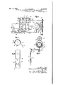
- Fig. 2 is a front elevation of the adjusting screens of a negative film.
- FIG. 3 is a side elevation thereof.
- Fig. 4- is an elevation of the members control- 55; ling the displacements of the movable screens.
- PATENT OFFICE Fig. 5 is-an end view of one of said members.
- Fig. 6 shows a pilot strip and Figs. '7 and 8 respectively show in elevation and in man view the members by means of which said pilot strip automatically produces the variations of illumination.
- the device comprises as above mentioned, a fixed plate 4 having, for each negative as many winsows T, l", 1 etc. as there are positives to be 10 printed;
- movable screens 9'; 9, 9" etc. carried by rods 10, l0, In” etc. can be displacedand are held with running friction'between the'plate 4 and a second covering plate 4, for example by means of weak spring 16" blades I I fixed to each of saidrods.
- At the ends of said rods III are laterally fixed projections l2, l2, l2 et c. having spherical heads, which engage'in a groove I3 having a flared end l4 provided in a movable grooved member I5 serving as a guide.
- the member' l5' is displaced first towards the right in the direction of the arrow 1, by means which will be described hereinafter, so as to disengage the heads I2o'f the rods lllwhich remain stationary owing to the friction'produced by the springs I l.
- the member I5 is then displaced vertically in the direction of the arrow f, as shown in dotted lines inFig. 2, the amount which the screens 9 are to be displacedand then brought back towards the left in the direction of the arrow 3, one of the edges of th'e'fiared end I4 of the groove I3 successive'sively engaging during this return movement the heads l2- of the rods ll! so'as to displace the screens -9 one after the other in synchronism with the unwinding of the film.
- Eccentric sleeves I6, l6, l6", fitted to each other are loosely mounted on a fixed shaft l1.
- Each of said sleeves carries a pinion l8, l8, l8" which can be respectively brought into mesh, by means of ,electromagnets I9, l9, 19', with the pinions 20, 20, 20" etc. mounted with a rubbing fit on acohstantly rotating drive shaft 2
- Each of the sleeves is provided with a plate 23 (Fig. 5) having two abutments 24, 25 which impinge on .a projection 26 secured to the frame-so as to prevent the sleeves from rotating more than one half a revolution; the
- a plate 23 has furthermore a recess 21 in which engages the end of a lever 28 (Fig. 4) pivoted at 29 which normally prevents the sleeve from rotating; all the levers 28 of the sleeves
- a fork 32 pivoted on a pin 33 and secured to a lever 34 wh ch carries the grooved member l5 actuating the screen supporting rods Hi.
- the pin 33 is mounted in a carriage 35 which is adapted to be displaced in parallel relation to the shaft I! in a slide 36.
- Said carriage 35 is secured to a rod 3? carrying at its end a finger 38 engaged in a groove 39 provided in a drum 40 loosely mounted on a shaft 4
- the drum 49 can be secured to the shaft 4i by means of a clutch 44 controlled by the electro-magnet 45.
- the groove 39 has two spiral portions of different and opposite pitch 46, 4'! which are separated by a circular portion 48 extending perpendicularly to the generatrix of the drum.
- the pitch of the spiral section 41 of the groove 39 of the drum 40 and the speed of the latter are calculated in such a manner that the successive action of the member l5 on the screens 9 is synchronous with the unrolling of the film, so that each screen 9 is actuated when the same zone of the negative passes in front of the corresponding window 7 of the plate 4.
- the illumination adjustment device according to the invention has been described, for greater simplicity for a single negative.
- the device is multiplied as many times as there are negatives, each of the devices thus constituted being controlled by a special pilot strip.
- Fig. 6 shows a pilot strip 5
- a device has been shown by way of example for automatically controlling the illumination of two negatives, for example pictures and sounds, and comprising for this purpose two pilot strips 5
- levers 56, 56, 56" etc. bear with their bent and tapered ends 55, the number of said levers being equal to that of the eccentric sleeves
- At their ends opposite the pilot strips 56, 56, 56" etc. are pivoted by means of grooves 84, 84', 84 and and projections 58, 58, 58 with the supports 59, 59', 59"
- each of said trips having a current inlet terminal 6
- have a round perforation 64 which is engaged on one of the pins 65, 65 projecting from the passage 53 when the door 54 is open.
- the levers 56 are raised and the feed drums 66, 66 of the strips 5
- the projection; 6.9 provided on its inner face pushes the rod 10; and the angle piece H: carrying the pins 6.5, which move backwards and release the
- the angle piece II is provided with anappendix 12- in engagement with a finger 1-3 secured to a stirrup l4 pivoted at Hi-and supporting the levers 56, 56, 56".
- stirrup 14 moves downwards, thereby enabling the levers 56 to move downwardly when the notches 52. of the strips 5
- the angle piece 'H- furthermore carriesatenon I6 displacing the arm 11 actuating a fork l8 1 which causes the clutch member W to slide onthe shaft bymeans of the tenons 81- and the grooves 82 soas to engage the-clutch IQ-83 and automatically secure the feed drums 66 to their shaft 80 when the door 54 closes.
- a device for'regulating the illumination comprising asingle source of? light, a fixed plate provided in front of each negative with asmany narrow windows as there are positives to be printed and arranged one above the other for simultaneously projecting on each positive different adjacent regions ofthe negative, separate movable screens independent of each other arranged behind each of said windows, and common control means for successively displacing said screens in'synchronism with the unwinding of the negative film.
- a device for regulating. the illumination comprising a single source of light, a fixed plate provided in front of each negative with as many narrow windows asthereare positives to be printedand'arranged one above the other for simultaneously projecting, on each positive different adjacent regions of the-negative, separate movable screens independent of each other arranged behind each of said windows, rods-arranged parallel to the direction of unwinding of the film and respectively connected to said screens, a movable member successively acting on the ends of said rods in synchronism with the unwinding of the negative film.
- a device for regulating the illumination comprising in front of each negative film a plate provided withas many windows for projection arranged one above the, other aslther-e are positives to be printed, movable screens independent of each other arranged behind said windows, rods arranged parallel to the direction of unwinding of the film and respectively secured tothe said screens, a second.
- said grooved member transversely to the direction of unwinding of the film so as to disengage said projections, means for displacing said member parallelv to the direction of the film, said latter: means comprising a plurality of eccentric sleeves freely mounted on each other, and means for displacing said grooved member transversely to the direction of the film so that the spherical projections of the screen supporting rods are successively engaged by the flared end of the groove.
- a device for regulating the illumination comprising, in front of each negative film, a plate provided with as many windows for projection arranged one above the other asthere are positives-to be printed, movable screens independent of each other arrangedbe hind said windows, rods arranged parallel to the direction of unwinding of the film and respectively secured to the said screens, a second plate, leaf springs secured to the said rods for holding same with running friction between the plate with windows and said second plate, projections havingspherical heads fixed to the ends of said rods, a movable member and in said member a groove having a fiared end, arranged transversely to the direction of unwinding of the film and in whichare engaged the spherical heads of said projections, means for displacing-said grooved member transversely and parallel to the direction of unwinding of the film, said means comprising a fixed shaft arranged transversely to
- a device for regulating ly secured to the said screens a second plate, leaf springs secured to the said rods for holding same with running friction between the plate with windows and said second plate, projections having spherical heads fixed to the ends of said rods, a movable member and in said member a groove having a flared end, arranged transversely to the direction of unwinding of the film and in which are engaged the spherical heads of said projections, means for displacing said grooved member transversely and parallel to the direction of unwinding of the film, said means comprising a fixed shaft arranged transversely to the direction of unwinding of the film, a plurality of eccentric sleeves fitted onto each other and freely mounted on said shaft, a fork on the outer sleeve, a lever secured to said fork and the end of which is fixed to the grooved member actuating the screen supporting rod
- a device for regulating the illumination comprising in front of each negative film, a plate provided with as many windows for projection arranged one above the other as there are positives to be printed, movable screens independent of each other arranged behind said windows, rods arranged parallel to the direction of unwinding of the film and respectively secured to the said screens, a second plate, leaf springs secured to the said rods for holding same with running friction between the plate with windows and said second plate, projections having spherical heads fixed to the ends of said rods, a movable member and in said member a groove having a flared end, arranged transversely to the direction of unwinding of the film and in which are engaged the spherical heads of said projections, means for displacing said grooved member transversely and parallel to the direction of unwinding of the film, said means comprising a fixed shaft arranged transversely to the direction of unwinding of the film, said means comprising a fixed shaft arranged transversely to the direction of unwinding of the film, said
- a device for regulating the illumination comprising in front of each negative film, a plate provided with as many windows for projection arranged one above the other as there are positives to be printed, movable screens independent of each other arranged behind said windows, rods arranged parallel to the direction of unwinding of the film and a respectively secured to the said screens, a.
- a device for regulating the illumination comprising, in front of each negative film, a plate provided with as many windows for projection arranged one above the other as there are positives to be printed, movable screens independent of each other arranged behind said windows, rods arrange parallel to the direction of unwinding of the film and respectively secured to the said screens, a second plate, leaf springs secured to said rods for holding same with running friction between the plate with windows and said second plate, projections having spherical heads fixed to the ends of said rods, a movable member and in said member a groove having a flared end, arranged transversely to the direction of unwinding of the film and in which are engaged the spherical heads of said projections, means for displacing said grooved member transversely and parallel to the direction of unwinding of the film, said means comprising a fixed shaft arranged transversely to the direction of unwinding of the film,
- a device for regulating the illumination comprising, in front of each negative film, a plate provided with as many windows for projection arranged one above the other as there are positives to be printed, movable screens independent of each other arranged behind said windows, rods arranged parallel to the directions of unwinding of the film and respectively secured to the said screens, a second plate, leaf springs secured to said rods for holding same with running friction between the plate with windows and said second plate, projections having spherical heads fixed to the ends of said rods, a movable member and in said member a groove having a flared end, arranged transverselyto the direction of unwinding of the film and in which are engaged the spherical heads of said projections, means for displacing said grooved member transversely and parallel to the direction of unwinding of the film, said means comprising a fixed shaft arranged transversely to the direction of unwinding of the film
- a device for regulating the illumination comprising, in front of each negative film, a plate provided with as many windows for projection arranged one above the other as there are positives to be printed, movable screens independent of each other arranged behind said windows, rods arranged parallel to the direction of unwinding of the film and respectively secured to the said screens, a second plate, leaf springs secured to said rods for holding same with running friction between the plate with windows and said second plate, projections having spherical heads fixed to the ends of said rods, a movable member and in said member a groove having a fiared end, arranged transversely to the direction of unwinding of the film and in which are engaged the spherical heads of said projections, means for displacing said grooved member transversely and parallel to the direction of unwinding of the film, said means comprising a fixed shaft arranged transversely to the direction of unwinding of the film, said means comprising a fixed shaft arranged transversely to the direction of unwinding of the film,
Landscapes
- Physics & Mathematics (AREA)
- General Physics & Mathematics (AREA)
- Projection-Type Copiers In General (AREA)
Description
5 Sheets-Sheet 1 M. A. DALOTEL Filed Aug. 4, 1956 ON A PLURAL'ITY OF POSITIVES AT THE SAME TIME Dec. 13, 1938.
MACHINE FOR THE CONTINUOUS PRINTING 0F NEGATIVE FILMS M 2 8 u 9 e 3 3 J 1 5 555535 w M i I w 4 h S 3 DALOTEL s PRINTING OF NEGATIVE FIL Filed Aug. 4, 1936 MACHINE FOR THE GONTINUOU ON A PLURALITY OF POSITIVES AT THE SAME TIME Dec. 13, 1938.
m u u u u n u u u now u a w u u u n .D/ QW DD u k n92,
MDUQQDGDEEDDDDDBDQDDD Patented Dec. 13, 1938 UNITED STATES MACHINE FOR THE CONTlNUOUS PRINTING F NEGATIVE FILMS oNA BLURALITY 0F POSITIVES AT THE SAME TIME Maurice Albert Dalotel, Colombes, France, as
signor to Suzanne Rosalie Mathot, Paris,
France Application August 4, 1936; seria -No. 94,172
In France August 8,1935
11 Claims.
The-present invention relates to a machine for the continuous printing by projection of one or a plurality of negative films on a plurality of positives at the same time, of the type diagrammatically illustrated in Fig. l of the accompanying drawings in which the negative films, for example, picture negative I and a sound negative 2, as well as the positives 3, 3', 3" etc. are arranged side by side behind a plate 4 and fed m with a continuous movement, optical projection systems (not shown) composed of prisms and lenses being arranged'to project respectively on each positive, through the windows such as 5, 5" etc., or 6, 6', 6" etc., of the plated, if different zones near the negative or negatives being respectively in register with the windows 1, I, l etc., or 8, 8, 8" etc, of the said plate.
It has already been proposed in machines of 20 this' kind to use for illuminating the negative film or films such as I, 2, a lamp of fixed intensity and to adjust the illumination, or more correctly the plate being adapted to be displaced variable amounts, so as to more or less close the windows I, I, 1" and 8, 8, 8". However, in this device the adjustment of all the windows corresponding to 'the'various zones near the negative or' negatives which are simultaneously projected on the various positives is effected at the same time, so that; on the various positives, the change of light does not appear on the same part of the strip.
The" device according to the present invention has for its object to overcome this drawback and it is characterized by the fact that it comprises movable screens which are independent of each 40 other, arranged behind the projecting windows of the negative films, and means for successively controlling the displacements of said screens in synchronism with the unwinding of the negative films.
By way of example, an embodiment of the deviceaccording to the invention has been described hereinafter and illustrated in the accompanying drawings.
Fig. 1 shows diagrammatically a complete or) printing machine of the above referred to-type.
Fig. 2 is a front elevation of the adjusting screens of a negative film.
3 is a side elevation thereof. Fig. 4-is an elevation of the members control- 55; ling the displacements of the movable screens.
PATENT OFFICE Fig. 5is-an end view of one of said members.
Fig. 6 shows a pilot strip and Figs. '7 and 8 respectively show in elevation and in man view the members by means of which said pilot strip automatically produces the variations of illumination.
Referring to Figs. 2 and 3, it will be seen that the device comprises as above mentioned, a fixed plate 4 having, for each negative as many winsows T, l", 1 etc. as there are positives to be 10 printed; In front of said windows movable screens 9'; 9, 9" etc. carried by rods 10, l0, In" etc. can be displacedand are held with running friction'between the'plate 4 and a second covering plate 4, for example by means of weak spring 16" blades I I fixed to each of saidrods. At the ends of said rods III are laterally fixed projections l2, l2, l2 et c. having spherical heads, which engage'in a groove I3 having a flared end l4 provided in a movable grooved member I5 serving as a guide.
When a change of light takes place, the member' l5'is displaced first towards the right in the direction of the arrow 1, by means which will be described hereinafter, so as to disengage the heads I2o'f the rods lllwhich remain stationary owing to the friction'produced by the springs I l. The member I5 is then displaced vertically in the direction of the arrow f, as shown in dotted lines inFig. 2, the amount which the screens 9 are to be displacedand then brought back towards the left in the direction of the arrow 3, one of the edges of th'e'fiared end I4 of the groove I3 succes'sively engaging during this return movement the heads l2- of the rods ll! so'as to displace the screens -9 one after the other in synchronism with the unwinding of the film.
Ihe vertical displacement of the'member i5 is obtained by means of the members shown in Figs. 3 and i: 4
Eccentric sleeves I6, l6, l6", fitted to each other are loosely mounted on a fixed shaft l1. Each of said sleeves carries a pinion l8, l8, l8" which can be respectively brought into mesh, by means of ,electromagnets I9, l9, 19', with the pinions 20, 20, 20" etc. mounted with a rubbing fit on acohstantly rotating drive shaft 2|; said pinionscan be brought into mesh with the pinions [8, I 8", l8 etc. by means of the clutches 22', 22', 22" etc; actuated by the aforesaid electro-magnets l9. Each of the sleeves is provided with a plate 23 (Fig. 5) having two abutments 24, 25 which impinge on .a projection 26 secured to the frame-so as to prevent the sleeves from rotating more than one half a revolution; the
On the outer sleeve I6 is mounted a fork 32 pivoted on a pin 33 and secured to a lever 34 wh ch carries the grooved member l5 actuating the screen supporting rods Hi. The pin 33 is mounted in a carriage 35 which is adapted to be displaced in parallel relation to the shaft I! in a slide 36. Said carriage 35 is secured to a rod 3? carrying at its end a finger 38 engaged in a groove 39 provided in a drum 40 loosely mounted on a shaft 4| which is constantly rotated by the drive shaft 2| through the instrumentality of pinions 42, 43. The drum 49 can be secured to the shaft 4i by means of a clutch 44 controlled by the electro-magnet 45.
The groove 39 has two spiral portions of different and opposite pitch 46, 4'! which are separated by a circular portion 48 extending perpendicularly to the generatrix of the drum.
The operation of the device is as follows:
When a change of light takes place a pilot strip efiects, in the manner which Will be described hereinafter, through the instrumentality of the electro-magnets |9, i9, i9 etc. and 45 respectively, the engagement of the clutches 22, 22, 22 etc. and of the clutch 45 of the drum 40. The sleeves i6, i6, i6 etc. are prevented from rotating for the time being by the locking levers 28, 23, 28", etc. The rotation of the cam drum 45 causes, by means of the spiral section 46 of the groove 39, a displacement towards the right of the carriage 35 and consequently of the member l5 (Figs. 2 and 3) which thereby releases the heads |2 of the screen supporting rods it. When the finger 38 comes into the section 43 of the groove 39, the carriage 35 impinges on the end of the coupling rod 39 of the locking levers 28 which swing towards the left releasing the sleeves it, so that those of said sleeves which have been engaged with the drive shaft 2| rotate half a revolution while the carriage 35 remains at the dead centre. The rotation of the eccentric sleeves l6 causes the fork 32 to swing towards the right or left (Fig. 3 in dotted lines) and consequently the end of the lever 34 and the grooved member i5 carried by said lever to be displaced upwardly or downwardly. The amount of the vertical displacement of the member I5 and consequently that of the variation of illumination therefore depends on the number of sleeve 5 which have been caused to rotate. Then, the spiral section 4? of the groove 39 of the drum 40 causes the carriage 35 to return to its initial position and consequently the displacement towards the left of the member |5 the groove l3 of which successively acts with its flared end M on the screen supporting rods I0, as has already been mentioned.
The pitch of the spiral section 41 of the groove 39 of the drum 40 and the speed of the latter are calculated in such a manner that the successive action of the member l5 on the screens 9 is synchronous with the unrolling of the film, so that each screen 9 is actuated when the same zone of the negative passes in front of the corresponding window 7 of the plate 4.
After the drum 40 has rotated one revolution, the clutch 44 of the latter is automatically released and the drum 49 remains inoperative until the following change of light.
Those of the clutches 22, 22', 22 which have been engaged remain engaged; when the following change of light takes place, which will necessitate another combination of eccentric sleeves, certain of the clutches 22, 22', 22" etc. which have been previously engaged, will be released, and the retracting springs 3| will return the corresponding sleeves to the inoperative position.
The illumination adjustment device according to the invention has been described, for greater simplicity for a single negative. In the event of the printing machine being intended to simultaneously project a plurality of negatives such as pictures, words, music, noise, the device is multiplied as many times as there are negatives, each of the devices thus constituted being controlled by a special pilot strip.
Fig. 6 shows a pilot strip 5| of this kind comprising notches such as 52, 52 etc., the number of juxtaposed notches on the same transverse row corresponding to the number of eccentric sleeves |6, |6 etc. which are to be brought into place at a given time.
In Figs. 7 and 8 a device has been shown by way of example for automatically controlling the illumination of two negatives, for example pictures and sounds, and comprising for this purpose two pilot strips 5|, 5| passing in a passage 53 closed by a door 54. On each pilot strip, levers 56, 56, 56" etc. bear with their bent and tapered ends 55, the number of said levers being equal to that of the eccentric sleeves |6, l6, l6" etc. of Fig. 4, said levers being all pivoted about a common pin 51. At their ends opposite the pilot strips 56, 56, 56" etc. are pivoted by means of grooves 84, 84', 84 and and projections 58, 58, 58 with the supports 59, 59', 59"
of the mercury trips 60, 60', 60 etc. pivoted about the common pin 85, each of said trips having a current inlet terminal 6|, 6|, GI and two outlet terminals 62, 62, 62" and 63, 63, 63 etc.: the terminals 62, 62, 62" are respectively connected to the electro-magnets l9, I9, l9" etc. actuating the clutch of the eccentrics l6, l6, l6" etc. (Fig. 4) whereas the terminals 63, 63, 63" are all connected to the electro-magnet 45 actuating the clutch of the cam drum 40.
The operation of this device is as follows:
When a notch such as 52 of the pilot strip 5| comes opposite the end 55 of a lever 56, the latter, which is no longer supported by the pilot strip, falls (position shown in full lines in Fig. 7), and the corresponding trip 60 sends current into the electro-magnet IQ of the corresponding eccentric l6 and into the electro-magnet 45 of the cam drum 40 actuating the illumination adjustment device in the manner hereinbefore described. Then, the edge of the notch 52 of the pilot strip which is displaced and acts on the end 55 of the lever 56, moves the latter upwardly (position in dotted lines in Fig. 7) and the trip cuts off the current. If slots 52, 52, 52" are arranged on the row of the pilot strip 5|, a plurality of levers 56 and consequently a plurality of eccentrics 60 will be brought into play.
For placing them in position, the pilot strips 5| have a round perforation 64 which is engaged on one of the pins 65, 65 projecting from the passage 53 when the door 54 is open. At this time, the levers 56 are raised and the feed drums 66, 66 of the strips 5|, 5| are loose on their pins 80, so that their teeth 61 can accurately engage in the lateral perforations 63 of the pilot pilot strips;
strips. When the door 54- is c1osed, the projection; 6.9 provided on its inner face pushes the rod 10; and the angle piece H: carrying the pins 6.5, which move backwards and release the The angle piece II is provided with anappendix 12- in engagement with a finger 1-3 secured to a stirrup l4 pivoted at Hi-and supporting the levers 56, 56, 56". When the angle piece II moves backwards asthe door- 54 closes, the
The angle piece 'H- furthermore carriesatenon I6 displacing the arm 11 actuating a fork l8 1 which causes the clutch member W to slide onthe shaft bymeans of the tenons 81- and the grooves 82 soas to engage the-clutch IQ-83 and automatically secure the feed drums 66 to their shaft 80 when the door 54 closes.
I claim:
1 In a machine for the continuous printing by projection of negative films on a plurality of positive films at the same time, a device for'regulating the illumination comprising asingle source of? light, a fixed plate provided in front of each negative with asmany narrow windows as there are positives to be printed and arranged one above the other for simultaneously projecting on each positive different adjacent regions ofthe negative, separate movable screens independent of each other arranged behind each of said windows, and common control means for successively displacing said screens in'synchronism with the unwinding of the negative film.
2; In a machine for the continuous printing by projection of negative films on a plurality of positive films at the same time, a device for regulating. the illumination comprising a single source of light, a fixed plate provided in front of each negative with as many narrow windows asthereare positives to be printedand'arranged one above the other for simultaneously projecting, on each positive different adjacent regions of the-negative, separate movable screens independent of each other arranged behind each of said windows, rods-arranged parallel to the direction of unwinding of the film and respectively connected to said screens, a movable member successively acting on the ends of said rods in synchronism with the unwinding of the negative film.
3, In armachine for the continuous printing by projection of negative fiims onaplurality of positive films at the same time, a device for regulating the illumination comprising in front of each negative film a plate provided withas many windows for projection arranged one above the, other aslther-e are positives to be printed, movable screens independent of each other arranged behind said windows, rods arranged parallel to the direction of unwinding of the film and respectively secured tothe said screens, a second. plate, leaf springs secured to the, said rods for holding same with running frictions between the plate with windows andsaid second plate, projections having spherical heads fixed to; the ends of said rods, a movable member and in said'member a groove having a flared end, arranged transversely to the direction of unwinding, of: the film and in which are engaged the spherical heads of said projections, means for displacingsaid grooved member transversely andparallel to the direction of unwindingof the film.
4, Ina machinefor the continuous printing'bymany windows for projection arranged one above the other as there are positives tobe printed, movable. screens independent of each other. arranged behind said windows, rods arranged parallelto the direction of unwinding of the film and respectively secured to the said screens, a second plate, leaf springs secured to the said rods for holding same with running friction between the plate with windows and said second plate, projeotionshaving spherical heads fixed to the ends of: said rods, a movable member and in said member a groove having a-fiared end, arranged transversely to the direction of unwinding of the film and in which are engaged the spherical heads of said projections, means fordisplacing. said grooved member transversely to the direction of unwinding of the film so as to disengage said projections, means for displacing said member parallelv to the direction of the film, said latter: means comprising a plurality of eccentric sleeves freely mounted on each other, and means for displacing said grooved member transversely to the direction of the film so that the spherical projections of the screen supporting rods are successively engaged by the flared end of the groove.
5; In a machine for the continuous printing by' projection of negative films on a plurality of positive films at the same time, a device for regulating the illumination, comprising, in front of each negative film, a plate provided with as many windows for projection arranged one above the other asthere are positives-to be printed, movable screens independent of each other arrangedbe hind said windows, rods arranged parallel to the direction of unwinding of the film and respectively secured to the said screens, a second plate, leaf springs secured to the said rods for holding same with running friction between the plate with windows and said second plate, projections havingspherical heads fixed to the ends of said rods, a movable member and in said member a groove having a fiared end, arranged transversely to the direction of unwinding of the film and in whichare engaged the spherical heads of said projections, means for displacing-said grooved member transversely and parallel to the direction of unwinding of the film, said means comprising a fixed shaft arranged transversely to the direction of unwinding of the film, a plurality of eccentric sleeves fitted onto each other and freely mounted on said shaft, a fork on the outer sleeve,- a lever secured to said fork and the end of which is fixed to the grooved member actuating the screen supporting rods, a carriage adaptecl'to be-displaced parallel to thesleeve shaft and on which said fork is pivoted, adrum having a groove composed of two spiral sections of opposite pitchconnectedto each other by a circular section, a finger-secured to said carriage and engaged in the groove of said drum, and meansfor separately'rotating the eccentric sleeves and the driun.
6. In a machine for the continuous printing-by projection of negative films on a plurality of posi-- tive films at the same time, a device for regulating ly secured to the said screens, a second plate, leaf springs secured to the said rods for holding same with running friction between the plate with windows and said second plate, projections having spherical heads fixed to the ends of said rods, a movable member and in said member a groove having a flared end, arranged transversely to the direction of unwinding of the film and in which are engaged the spherical heads of said projections, means for displacing said grooved member transversely and parallel to the direction of unwinding of the film, said means comprising a fixed shaft arranged transversely to the direction of unwinding of the film, a plurality of eccentric sleeves fitted onto each other and freely mounted on said shaft, a fork on the outer sleeve, a lever secured to said fork and the end of which is fixed to the grooved member actuating the screen supporting rods, a carriage adapted to be displaced parallel to the sleeve shaft and on which said fork is pivoted, a drum having a groove composed of two spiral sections of opposite pitch connected to each other by a circular section, a finger secured to said carriage and engaged in the groove of said drum, and pinions respectively secured to the eccentric sleeves and the grooved drum, a constantly rotating drive shaft, pinions mounted on said drive shaft, electro-magnets for separately bringing said latter pinions into mesh with those of the eccentric sleeves and of the grooved drum, locking members for the eccentric sleeves and means for releasing said locking members by means of the displaceable carriage when the grooved member releases the spherical projections of the screen supporting rods.
'7. In a machine for the continuous printing by projection of negative films on a plurality of positive films at the same time, a device for regulating the illumination, comprising in front of each negative film, a plate provided with as many windows for projection arranged one above the other as there are positives to be printed, movable screens independent of each other arranged behind said windows, rods arranged parallel to the direction of unwinding of the film and respectively secured to the said screens, a second plate, leaf springs secured to the said rods for holding same with running friction between the plate with windows and said second plate, projections having spherical heads fixed to the ends of said rods, a movable member and in said member a groove having a flared end, arranged transversely to the direction of unwinding of the film and in which are engaged the spherical heads of said projections, means for displacing said grooved member transversely and parallel to the direction of unwinding of the film, said means comprising a fixed shaft arranged transversely to the direction of unwinding of the film, a plurality of eccentric sleeves fitted onto each other and freely mounted on said shaft, a fork on the outer sleeve, a lever secured to said fork and the end of which is fixed to the grooved member actuating the screen supporting rods, a carriage adapted to be displaced parallel to the sleeve shaft and on which said fork is pivoted, a drum having a groove composed of two spiral sections of opposite pitch connected to each other by a circular section, a finger secured to said carriage and engaged in the groove of said drum, pinions respectively secured to the eccentric sleeves and the grooved drum, a constantly rotating drive shaft, pinions mounted on said drive shaft, electro-magnets for separately bringing said latter pinions into mesh with those of the eccentric sleeves and of the grooved drum, locking members for the eccentric sleeves and means for releasing said locking members by means of the displaceable carriage when the grooved member releases the spherical projections of the screen supporting rods, means for limiting the rotation of the eccentric sleeves to one half a revolution and springs for retracting said sleeves into their initial position as soon as the actuating pinions are disengaged.
8. In a machine for the continuous printing by projection of negative films on a plurality of positive films at the same time, a device for regulating the illumination, comprising in front of each negative film, a plate provided with as many windows for projection arranged one above the other as there are positives to be printed, movable screens independent of each other arranged behind said windows, rods arranged parallel to the direction of unwinding of the film and a respectively secured to the said screens, a. second plate, leaf springs secured to said rods, for holding same with running friction between the plate with windows and said second plate, projections having spherical heads fixed to the ends of said rods, a movable member and in said member a groove having a flared end, arranged transversely to the direction of unwinding of the film and in which are engaged the spherical heads of said projections, means for displacing said grooved member transversely and parallel to the direction of unwinding of the film, said means comprising a fixed shaft arranged transversely to the direction of unwinding of the film, a plurality of eccentric sleeves fitted onto each other and freely mounted on said shaft, a fork on the outer sleeve, a lever secured to said fork and the end of which is fixed to the grooved member actuating the screen supporting rods, a carriage adapted to be displaced parallel to the sleeve shaft and on which said fork is pivoted, a drum having a groove composed of two spiral sections of opposite pitch connected to each other by a circular section, a finger secured to said carriage and engaged in the groove of said drum, a perforated pilot strip, and means for separately rotating the eccentric sleeves and the grooved drum by means of said pilot strip.
9. In a machine for the continuous printing by projection of negative films on a plurality of positive films at the same time, a device for regulating the illumination comprising, in front of each negative film, a plate provided with as many windows for projection arranged one above the other as there are positives to be printed, movable screens independent of each other arranged behind said windows, rods arrange parallel to the direction of unwinding of the film and respectively secured to the said screens, a second plate, leaf springs secured to said rods for holding same with running friction between the plate with windows and said second plate, projections having spherical heads fixed to the ends of said rods, a movable member and in said member a groove having a flared end, arranged transversely to the direction of unwinding of the film and in which are engaged the spherical heads of said projections, means for displacing said grooved member transversely and parallel to the direction of unwinding of the film, said means comprising a fixed shaft arranged transversely to the direction of unwinding of the film, a plurality of eccentric sleeves fitted onto each other and freely mounted on said shaft, a fork on the outer sleeve, a lever secured to said fork and the end of which ail is fixed to the grooved member actuating the screen supporting rods, a carriage adapted to be displaced parallel to the sleeve shaft and on which said fork is pivoted, a drum having a a groove composed of two spiral sections of opposite pitch connected to each other by a circular section, a finger secured to said carriage and engaged in the groove of said drum, pinions respectively secured to the eccentric sleeves and the grooved drum, a constantly rotating drive shaft, pinions mounted on said drive shaft, electro-magnets for bringing said pinions separately into mesh with those of the eccentric sleeves and of the grooved drum, a perforated pilot strip, a number of levers equal to the number of eccentric sleeves and arranged so as to bear on the pilot strip and to move when a perforation of said pilot strip passes, two electric contacts actuated by each lever and one of which is arranged in the circuit of the electro-magnet of one of the eccentric sleeves and the other in the circuit of the electro-magnet controlling the grooved drum.
10. In a machine for the continuous printing by projection of negative films on a plurality of positive films at the same time, a device for regulating the illumination comprising, in front of each negative film, a plate provided with as many windows for projection arranged one above the other as there are positives to be printed, movable screens independent of each other arranged behind said windows, rods arranged parallel to the directions of unwinding of the film and respectively secured to the said screens, a second plate, leaf springs secured to said rods for holding same with running friction between the plate with windows and said second plate, projections having spherical heads fixed to the ends of said rods, a movable member and in said member a groove having a flared end, arranged transverselyto the direction of unwinding of the film and in which are engaged the spherical heads of said projections, means for displacing said grooved member transversely and parallel to the direction of unwinding of the film, said means comprising a fixed shaft arranged transversely to the direction of unwinding of the film, a plurality of eccentric sleeves fitted onto each other and freely mounted on said shaft, a fork on the outer sleeve, a lever secured to said fork and the end of which is fixed to the grooved member actuating the screen supporting rods, a carriage adapted to be displaced parallel to the sleeve shaft and on which said fork is pivoted, a drum having a groove composed of two spiral sections of opposite pitch connected to each other by a circular section, a finger secured to said carriage and engaged in the groove of said drum, pinions respectively secured to the eccentric sleeves and the grooved drum, a constantly rotating drive shaft, pinions mounted on said drive shaft, electro-magnets for bringing said pinions separately into mesh with those of the eccentric sleeves and of the grooved drum, a perforated pilot strip, a number of levers equal to the number of eccentric sleeves and arranged so as to bear on the pilot strip and to move when a perforation of said pilot strip passes, mercury trips respectively pivoted on each of said levers, each of said mercury trips having one current inlet terminal and two outlet terminals, one of the outlet terminals of each trip being connected to the electro-magnet controlling the corresponding eccentric sleeve and the second outlet terminal of all the trips being connected to the electro-magnet controlling the grooved drum.
11. In a machine for the continuous printing by projection of negative films on a plurality of positive films at the same time, a device for regulating the illumination comprising, in front of each negative film, a plate provided with as many windows for projection arranged one above the other as there are positives to be printed, movable screens independent of each other arranged behind said windows, rods arranged parallel to the direction of unwinding of the film and respectively secured to the said screens, a second plate, leaf springs secured to said rods for holding same with running friction between the plate with windows and said second plate, projections having spherical heads fixed to the ends of said rods, a movable member and in said member a groove having a fiared end, arranged transversely to the direction of unwinding of the film and in which are engaged the spherical heads of said projections, means for displacing said grooved member transversely and parallel to the direction of unwinding of the film, said means comprising a fixed shaft arranged transversely to the direction of unwinding of the film, a plurality of eccentric sleeves fitted onto each other and freely mounted on said shaft, a fork on the outer sleeve, a lever secured to said fork and the end of which is fixed to the grooved member actuating the screen supporting rods, a carriage adapted to be displaced parallel to the sleeve shaft and on which said fork is pivoted, a drum having a groove composed of two spiral sections of opposite pitch connected to each other by a circular section, a finger secured to said carriage and engaged in the groove of said drum, a perforated pilot strip, members for feeding said strip, a number of levers equal to the number of eccentric sleeves and arranged so as to bear on the pilot strip and to move when a perforation of said pilot strip passes, two electric contacts actuated by each lever and one of which is arranged in the circuit of the electro-magnet of one of the eccentric sleeves and the other in the circuit of the electro-magnet controlling the grooved drum, and means for locking the levers actuated by the pilot strip and for simultaneously disengaging the members for feeding said strip.
MAURICE ALBERT DALOTEL.
Applications Claiming Priority (1)
| Application Number | Priority Date | Filing Date | Title |
|---|---|---|---|
| FR2139806X | 1935-08-08 |
Publications (1)
| Publication Number | Publication Date |
|---|---|
| US2139806A true US2139806A (en) | 1938-12-13 |
Family
ID=9684067
Family Applications (1)
| Application Number | Title | Priority Date | Filing Date |
|---|---|---|---|
| US94172A Expired - Lifetime US2139806A (en) | 1935-08-08 | 1936-08-04 | Machine for the continuous printing of negative films on a plurality of positives at the same time |
Country Status (1)
| Country | Link |
|---|---|
| US (1) | US2139806A (en) |
-
1936
- 1936-08-04 US US94172A patent/US2139806A/en not_active Expired - Lifetime
Similar Documents
| Publication | Publication Date | Title |
|---|---|---|
| US2481694A (en) | Illumination control for photographic copying apparatus | |
| US2117727A (en) | Means for controlling printing lights | |
| US2269400A (en) | High-speed between-the-lens photographic shutter | |
| US3007369A (en) | Photographic reproducing machine | |
| US2616331A (en) | Projection printer | |
| US2139806A (en) | Machine for the continuous printing of negative films on a plurality of positives at the same time | |
| US1955938A (en) | Motion picture projecting machine | |
| US2699703A (en) | Photographic reproduction apparatus | |
| US2308725A (en) | Photographic shutter and synchronizing system | |
| US2122689A (en) | Apparatus for copying color film | |
| US2457913A (en) | Film gate | |
| US1976346A (en) | Control for a photographic recording apparatus | |
| US2322734A (en) | Reflex camera with grid shutter | |
| US2649018A (en) | Control mechanism for photographic copying apparatus | |
| US2086547A (en) | Matrix distributor control for line composing machines | |
| US2153211A (en) | Composite printing of motion picture | |
| US2601181A (en) | Device for driving a film in a multifilm cinematographic projector | |
| US2584964A (en) | Film advancing means for cameras, including film pawls or curtain shutters | |
| US1205582A (en) | Motion-picture-printing machine. | |
| GB182887A (en) | Mechanism for the photographic reproduction of type or other characters | |
| US1591436A (en) | Machine for the automatic coloring of films | |
| US2961935A (en) | Photographic shutter | |
| US1965366A (en) | Motion picture apparatus | |
| US1023797A (en) | Moving-picture apparatus. | |
| US1803398A (en) | Light control for printers |