US2139783A - Game - Google Patents
Game Download PDFInfo
- Publication number
- US2139783A US2139783A US9992A US999235A US2139783A US 2139783 A US2139783 A US 2139783A US 9992 A US9992 A US 9992A US 999235 A US999235 A US 999235A US 2139783 A US2139783 A US 2139783A
- Authority
- US
- United States
- Prior art keywords
- ball
- board
- switch
- pin
- electromagnet
- Prior art date
- Legal status (The legal status is an assumption and is not a legal conclusion. Google has not performed a legal analysis and makes no representation as to the accuracy of the status listed.)
- Expired - Lifetime
Links
- 239000004020 conductor Substances 0.000 description 18
- 230000007246 mechanism Effects 0.000 description 17
- 230000003028 elevating effect Effects 0.000 description 10
- 238000005266 casting Methods 0.000 description 7
- 230000000694 effects Effects 0.000 description 7
- 241000239290 Araneae Species 0.000 description 6
- 230000000994 depressogenic effect Effects 0.000 description 5
- 239000011521 glass Substances 0.000 description 4
- 230000003111 delayed effect Effects 0.000 description 3
- 238000003780 insertion Methods 0.000 description 3
- 230000037431 insertion Effects 0.000 description 3
- 239000002184 metal Substances 0.000 description 3
- 229910052751 metal Inorganic materials 0.000 description 3
- 238000010276 construction Methods 0.000 description 2
- 238000010586 diagram Methods 0.000 description 2
- 210000000887 face Anatomy 0.000 description 2
- 230000005484 gravity Effects 0.000 description 2
- XEEYBQQBJWHFJM-UHFFFAOYSA-N iron Substances [Fe] XEEYBQQBJWHFJM-UHFFFAOYSA-N 0.000 description 2
- 229910052742 iron Inorganic materials 0.000 description 2
- 108010062580 Concanavalin A Proteins 0.000 description 1
- 101100096502 Danio rerio spring gene Proteins 0.000 description 1
- 241000158723 Melia Species 0.000 description 1
- 235000002779 Morchella esculenta Nutrition 0.000 description 1
- 240000002769 Morchella esculenta Species 0.000 description 1
- 101100096504 Mus musculus Spring1 gene Proteins 0.000 description 1
- 101100426090 Rattus norvegicus Trim9 gene Proteins 0.000 description 1
- 101100096505 Xenopus laevis spring1 gene Proteins 0.000 description 1
- 230000015572 biosynthetic process Effects 0.000 description 1
- 239000003086 colorant Substances 0.000 description 1
- 239000011810 insulating material Substances 0.000 description 1
- 230000000750 progressive effect Effects 0.000 description 1
- 238000009877 rendering Methods 0.000 description 1
- 238000005096 rolling process Methods 0.000 description 1
Images


Classifications
-
- A—HUMAN NECESSITIES
- A63—SPORTS; GAMES; AMUSEMENTS
- A63F—CARD, BOARD, OR ROULETTE GAMES; INDOOR GAMES USING SMALL MOVING PLAYING BODIES; VIDEO GAMES; GAMES NOT OTHERWISE PROVIDED FOR
- A63F7/00—Indoor games using small moving playing bodies, e.g. balls, discs or blocks
- A63F7/02—Indoor games using small moving playing bodies, e.g. balls, discs or blocks using falling playing bodies or playing bodies running on an inclined surface, e.g. pinball games
- A63F7/025—Pinball games, e.g. flipper games
- A63F7/027—Pinball games, e.g. flipper games electric
Definitions
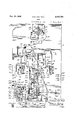
- VAN TUYL GAME Filed March 8, 1955 ll Sheets-Sheet 9 Dec. 13,1933.
- VAN TUYL 2,139,783 VAN TUYL 2,139,783
- This invention relates to a. game played yon a board or table, of the general type called .a pin board or pin game.
- Such games vare usually played with balls by means of a springpressed plunger manually released, with thev bject of placing the balls in certain desired positions or pockets upon the table.
- the principal object of the invention is to provide an improved game of this type which simulates football.
- a further object of the invention is to provide improved mechanism for use in such games.
- Fig. 2 is a rear view of the gam-ev board .showing the mechanism mounted thereon;
- Fig. 3 is a wiring diagram showing the electrical system and associated parts in the same relation as in Fig. 2;
- Fig. 4 is a fragmentary plan View of one corner i of the cabinet with the glass cover and the playing boardl removed showing the coin chute and tilting switch and related parts;
- Fig. 5 is a Vertical sectional detail View, taken on the line 5-5 of Fig. 4, with the playing board 'i and glass cover in position;
- Fig'. 6 is a sectional detail, taken on the line 6 6 of Fig. 5;
- Fig. 7 is a sectional detail view, taken on the line T T of Fig. 5;
- Fig. 8 is a fragmentary sectional plan view, taken on the line 8-8 of Fig. ⁇ 9 j
- Fig. ⁇ 9 is a fragmentary sectional View, taken on the line 9-9 of Fig. 8;
- Fig. 10 is a. sectional detail view, taken on the line lD-I of Fig. 9;
- Fig. 11 is a sectional detail view, taken on the line IIL-H of Fig. l0;
- Fig. 12 is a sectional detail view, taken on the line
- Fig. k17v is a sectional detail view, taken on the line -I-L'I-v-H of,Fig. A15;
- Fig, .18 is asectionaldetail view, taken on the Eig. 251i isairentelevational ,view ofthe quarterback showing themechanismtherebeneath in section.. takenonthe line 237-123- of Fig. 21;
- Fig. 24 isa sectional detail view, taken on the line 24e-24 of 23;
- Fg.f.25 is. asideviewf of the yardage meter or indicator, .thegame board being shown in section;
- v- Fig. VV,26 a plan. View of. the indicator, taken 0n ⁇ the line -26-7-26 of Fig. 25;
- Fig..,28 anelevatio-nal detail showing parts illustrated Fig.. 25 in a different relation;
- 29 is asectionaldetail View, Vtaken on the line 29,--29- of Fig. ⁇ 2, on a 4considerably larger scale;
- Fig. 30 is asectional detail view, taken on the line 311-., 30 of Fig. 2, on a considerably ⁇ larger scale, and.v
- F1531 is .a sectional ydetail view, taken on the line re-3l of Fig. 30.
- the chute 4 extends aroundthe board 8 and its nal length lies parallel to itsinitial length, as best seen in ⁇ Fig. 1.
- the gate I0 closes and prevents its reentry into the chute 4. It will be understood that in order for the ball to run around the chute 4 and emerge through the gate I0 into the eld of play, it must be struck a substantial blow by the plunger 6. If the impact is not suiciently forcible, the ball will not emerge by the gate I9,
- the next ball is the first play ball and it emerges from the gate I0. Normally it emerges with some Yspeed so that it is carried around on, the inside ofV a rail I8, which is the inside wall of part of the chute 4, and strikes a spring buffer element I9 from which it rebounds. However, it may emerge from the gate I9 with insucient ⁇ way to carry it around into contact with the buffer I9. f In'either case, the ball rolls under gravity-down towards the player.
- the prime aim is to make touchdowns and this maybe done by directing the ball between pins 20 over the position of the pin I5 into the arms of a quarterback 2
- the pins I5 and 58 are operatively connected so that when one is up the other is down: 'I'heclosing of the switch 22 by the ball delivered by the quarterback has the eiect of freeing the ball on the gridiron so that it may run downwardly into awell 23 and in so doing this ball passes over a switch 24, which has the effect of opening the gate I4, closing the gates I2 and I3, and projecting the pin I5 upwardly and withdrawing the pin 58.
- I provide bars' 30 and I also provide bars 3l which form with bars 30 a pair of chutes 32.
- At the bottom of these chutes I provide opening 33 Vfor the escape of balls which may pass into these chutes. Owing to the location of these two chutes and the relation of obstructions, such as pins 25 and bars 29, it is comparatively easy to get a ball to pass into them.
- These chutes are no gain chutes and the ball passing into one of them corresponds to a play in which the team on oiensive fails to advance the ball. In passing into one of these chutes 32, the ball passes over a switch 34 which' records the play on the indicator 35.
- the indicator 35 records the number of downs or plays made, up to four until a touchdown or a ten-yard gain is made, whereupon the registry of the indicator returns to zero.
- the number of downs indicated by the indicator informs the player of the number of shots he has left within which he must make a ten-yard gain or a touchdown, in order to remain in play. If he fails to make a ten-yard gain or a touchdown with four play shots, the fork 5 moves forwardly so as to prevent the play of any further balls and a switch cuts the supply of energy away from the switches on the board.
- This indicator shows zero .at the beginning of a game.
- the switches 34 have no efyards. It can readily be seenin Fig.
- the bars 3'1 and 40 dene chutes 4I Rearwardly of the bars 40 I provide similar diverging bars 42 which, with the bars 40, define chutes 43. Rearwardly of the bars 42 I provide similar bars 44 which, with the bars 42, dene chutes 45. The bars 49, 42 and 44 are progressively shorter so that the balls have a certain opportunity, if skillfully directed, to pass into the chutes 43 and 45. Rearwardly of the bars 44 are provided two rows of pins which define a central rearward opening 46. lThe bars 3l, 40, 42 and 44y terminate at their lower, or forward, ends so as to provide a central passage 41 in alignment with the opening 46 and in alignment with the ⁇ passage 48 provided for the ball on the gridiron I I.
- switches 449, 50., 5I and 52 located respectively between the inner or forward ends of bars 31, 40, 42 and 44.
- a ball entering one of the chutes 4I passes over the switch 49 and is divertedv by the closed gate I4 into one of the openings 39.
- the closing of the switch 49 has the'effect of actuating the mechanism ⁇ of the grid-iron so ythat the ball at the initial position I6 is moved forward ten yards on the gridiron.
- a ball entering onefof the chutes 43 passes overthe switches 50 and 49, with the result that the mechanism on the gridiron is actuated twice and the ball onthe gridiron is advanced twenty yards. It may here be remarked that there is only one ball on they gridiron at a time. A ball enteringone of the chutes.
- the indicators or recorders 35 and 35 may be made to resemble a football in shape and color.
- the gridiron IIv is preferably green with white lines and numbers, and on each side I provide castings 54 made to resemble grandstands full of spectators.
- I provide this machine with a mechanism actuated by tilting which has the effect of locking the machine against further play in the event that a player tilts the cabinet in an unfair effort to divert the ball from the course determined by the impact given it by the plunger 6.
- a tilting indicator 55 which'is provided with a window 55 through which'means are visible which indicate Tilted or 0. K., as the case may be.
- the passage 48 on the gridiron is constituted by rails 9.0 which extend longitudinally of the gridiron II. Beneath these rails are provided in the board ⁇ 3 short transverse slots 5I and 52 which are staggered in the longitudinal direction of the gridiron, as best seen in Fig. 1.
- the slots BI and 62 extend somewhat inwardly of the rails SII and they are adapted to receive the teeth 53 and 64 of rake members 65 and so as to constitute an escapementswhereby the ball on the grldiron may befed forward the proper amount, depending. upon the playswhich advance the ball.
- the switches I'I, 22, 24, 34, 53 each comprise a piece. of ii'at stock which projects through a metalsocket beyond both faces of the board 8.
- the portion projecting below the under face of the board 8 is provided with an opening which receives.
- a ⁇ resilient leaf carrying a Contact When the piece ⁇ of stock is depressed by a ball passing over it, the leaf is also depressed, bringing its contact into engagement with a contacten an -adjacent leaf.
- I use a vsingle numeral to designateeach one. of these switches as a whole.
- two resilient switch leaves 68 with one of which the frame 5I engages, are moved towards each other so as to make contact between them. It will thus be noted that if the ball passes over the four switch elements 49, 50, 5I and 52, contact between the switch. leaves 68 will be made four times in succession. If the ball passes over the three elements 49, 50 and 5I, the switch leaves 68 will complete the circuit three times, and so forth.
- the swingingv of the frame 61 is controlled by adjustable abutments 6.9 and as best shown in Fig. 3l, the frame is normally biased so that the elements 49, 50, 5
- is in the form of a Crouching ,human figure having outstretched arms between which a ball is adapted to be received.
- the figure is mounted upon a circular plate 'I0 which occupies an opening '1
- the plate'lll is rotatably mounted by means of a shaft l2 upon a spider '
- the plate l0 carries a depending enlarged hub 14, to which is connected one end of a coil spring 15, the other end of which is secured to the spider 13.
- the spring 15 tends to bias the quarterback into ball-delivering position, that is, a position 180 degrees away from the position shown in Fig. 1.
- the locking is effected by the entrance of a pin 7,8 carried by a yoke 'I9 which is kpivotally mounted on the plate 'I0 and is biased upwardly by a sp-ring 80.
- the pin 18 enters a downwardly directed slot 8
- rI'he yoke 'I9 carries a small platform 83 in alignment with an opening 84 between the arms of the quarterback 2
- the pin 18 engages an inclined ramp 85 on the spider 'I3 so that the platform 83 is elevated substantially into the plane of the plate 10 so that the ball carried by the platform 83 may roll freely therefrom.
- the latch member 82 is provided with an inclined surface 86 which engages the pin '
- the strap 81 is drawn rearwardly by means of a lever 88 (Fig. 2) which has a resilient connection with a rod' 89 slidably mounted on the under side of the board 8.
- the rod 89 is normally biased towards the front or playing end of the machine by means of a spring 90 and it has a downwardly turned end 9
- 5 and 58 are provided with eyes through which pass portions of a frame 93, pivotally mounted onl the underside of the board 8 between these two ⁇ pins, so that one pin. is projected upwardly when the other isretracted, and vice versa.
- the frame 93 is actuated by means of a crank arm which forms part of a rocking frame 94, also pivotally mounted on the underside of the board 8.
- the rocking frame 94 is provided with another crank arm which passes through an eye on the lower end of a small rod 95.
- the rod 95 projects through an opening in the board and is operatively connected to the gate
- the frame 94 comprises an intermediate lengthv 98 displaced from its pivotal axis, which length engages a frame 9T also pivotally mounted on the under side ofthe board 8.
- the frame 91 comprises crank arms which receive eyes of small rods 98 which project through openings in the board 8 and are operatively connected to the gates l2 and
- the intermediate length 98 of the rocking frame 94 is connected by means-of a link 99 to the armature
- 02 is provided which locks the armature when moved into that position, either mechanically or by magnetic attraction.
- 00 tends to move away ⁇ from the latched position by gravity.
- 02 is biased towards latching positionby means of a spring
- 90 is moved to latched position in two ways. First, mechanically by the manual operation of the coin chute which causesa bell crank lever
- the downs counter or indicator 35 and the yardage meter 36 are of substantially the same construction, which construction will be readily understood with reference to Figs. 25 to 28 inclusive, in which the yardage meter isshown.
- This meter being adapted to record the number of three-yard gains made is provided with ascal-e 06 which carries the numbers 10, 7, 4, l, in series which are adapted to appear in series through the window in the football-like fitting mounted on the surface of the board 8.
- the scale is numb-ered 0, 1, 2, 3, 4, in series.
- the indicator or meter is mounted on the under side of th'e board 8 and an The scale
- 'Ihis spider is preferably formed of sheet metal and is integrally'con-A vertical wall of the frame, which is provided with openings
- On the otherside of the central wall from the ratchet are mounted electromagnetsvl
- 5 is pivotally mounted on a frame l2 and is part of an armature
- 8 is pivotally mounted on the frame l2 and at its free end pivotally carries a pawl
- 23 is connected to the armature
- 25 is provided for moving thel armature
- 26 is provided which is actuated each time the armature
- This switch may suitably comprise a pair of contact bearingleaves which are adapted to be engagedby the projecting end of the pivot carrying the pawl
- 21 is to lock the machine against further play,.until a further coin is inserted, as will more fully be explained bythe description' of the electrical system.
- 21 for the attainment of thisresult is suggested indotted lines on Fig. 27.
- the downsl meter also comprises an electromagnet
- the rake members 65 and 66 which carry the teeth -63- and 64 are pivotally mounted in plates
- the rake member 65 carries an armature
- the rake member 65 carries a rearwardly eX- tending Crank arm
- 38 is opened at-the commencement of play and is held open'longenough-sothat any ball on the board 8-may .rolly downwardly over the gridiron, into the Well 23 andV pastv the gate
- 42 is energized each time the switch 68 is closed, that is, every time a lO-yard gain is made.
- carries an arm
- 33 is .provided at one 75 end with a crank portion
- 46 causes the bar
- the bar comprises a major crank portionV
- the crank portion 41 is connected by a link
- 41 is returned to its initial position by a tension spring
- the time of the return can be controlled by suitable adjustment of the dashpot.
- 38 is rigidly mounted on a pivot bar
- 52 is a crank
- 53 extends into ⁇ a relatively long slot
- 41 draws the link
- 51 falls downwardly and the gate
- 41 has practically returned to its initial position, it engages the latch 51, as best seen in Fig. 16, and releases the crank
- 05 previously referred to is mounted upon a bracket
- 05 carries a rollerV
- is pivotally connected to a link
- 4 which is thus effected bythe forward movement of the coin slide has heretofore been described, likewise the mannerY in which the position .of these elements becomes changed at the start of play.
- the lower end of the pin 59 is ⁇ in the form of an eye which receives an arm
- 'I'hese plates are provided with openings which serve as a bearing Vfor a longitudinally slidable rod
- the rear end of this rod is provided with a cam
- 65 that is, movement to the right as viewed in this figure, will have the eiect of projecting the pin 59 above the surface of the board 8.
- the pin 59 is projected upwardly, and that the pin is maintained in projected condition Yas long'as the coin slide is held inwardly.
- the bar 33 returns to its initial positiongradually and the spring
- 'I'he tilting indicator 55 comprises a frame
- 81 is adapted to engage a pin
- 92 carries the fingers 5 which project upwardly through suitable slots in the board B into the chute 4.
- 91 carries'a laterally extending arm 28
- 41 to initial position. is delayed by the dashpot
- 92 is thus freed and is drawn rapidly forward by means of the spring
- 95 carries a downwardly projecting flange 292 on which is pivotally mounted a lever 283.
- the lever 203 is provided with a gate 204, the purpose of which will hereinafter be described.
- the lever 283 is provided with a slot 205 which receives a pin 289 carried by a depending lug 201 which is integral with the plate
- the gate 204 is likewise in its full line-position. The corresponding positions of these elements, when the plate
- On the under side of the board 8 are provided four electric contacts 208, 209, 2
- the board 3 which, together with the mechanism mounted thereon, has been described above in considerable detail, is mounted within a cabinet 2 2, being supported therein upon rails 213 at the requisite slope to enable the balls to roll downwardly by gravity towards the front or playing end of the machine.
- the board is firmly held in place by screws 2
- the surface of the board 8 is protected from interference by a sheet of glass 2
- the coin slide l, the ball elevating handle 2 and the plunger 8, previously mentioned', are mounted on the front wall of the cabinet.
- the cabinet is provided with a ball collecting hopper 218 which extends below the openings 9, 33, 39, and below the well 23, so that all the balls pass into the hopper.
- the hopper is provided with a discharge outlet 2
- is provided on thev board for preventing the ball being elevated from striking against the glass 214.
- the upper end of the guide 228 is bent" inwardly towards the chute 4, as indicated at 222.V
- ⁇ 9 falls against the guide 220 and rests upon a concave formation 223 at the end of a lever 224, ⁇ which is pivoted to the cabinet at 225.
- the lever 224 is provided with a long arcuate tail 228 whichcloses-the opening 2I9 during the time when the lever 224 is elevating the ball.
- a resilient stop Y221 is provided for maintaining the lever 224 in ball-receiving position.
- the ball elevating handle 2' is slidably mounted in a suitable bearing carried by the cabinet and its inner end is somewhat loosely secured to a link 228 which is provided with a slot in its rear end whereby the same is guided upon a bolt 229 mounted on the cabinet.
- the link 228 is operatively connected by meansof a relatively long spring 230 to a pin 23
- a bar 232 is pivotally mounted ⁇ on the pin 23
- the bar 232 is provided with a slot' 233 through which the bolt 229 passes and has its rear end bent laterally to provide the element 92, which has been previously described, and which engages the downwardly turned end 9
- An electric battery 245 (Fig. 3,) may be mounted within the cabinet, lfor the actuation of the electrical devices hereinabove described.
- One pole of the battery is connected to a resilient contact 234.
- the other pole is connected through a fuse 235 to a similar contact 236.
- a novel tilting switch 246 is provided for rendering the machine inoperative in the event an attempt is made to divert a ball under play into a more advantagous position.
- the tilting switch 246 is preferably provided within the cabinet and it may comprise a ring 231 adjustably mounted within the cabinet by means of a slotted arm 238 which is held in desired position by means of screws 239; One of the screws 239 and consequently the ring 231, is connected by means of av conductor to a resilient contact 240.
- is normally located within the eye 231. This coil spring carries at its lower end a weight 242 and at its upper end it is supported by a screw 243. The screw 243 is connected to a resilient Contact 244.
- the eye 231 is slightly larger than the maximum diameter of the spring 24
- the spring makes contact with the eye 231, with an eiect which will appear hereinafter in the following description.
- the contacts 234, 236, '240. and 244 are arranged in series and may suitably take the form of angle pieces of resilient metal. They are so located that they are engaged by the contacts 208, 209, 2
- the contact 209 is exclusively connected, by a conductor 241, to one of the leaves
- the contact 299 is connected by a conductor 248 to each of the electromagnets II1,
- J is connected by means of a conductor 249 to the switches I1,
- 1 is connected by a conductor 25
- The-switch 26, and both switches 34, are connected by conductor 252 to the magnet
- Both switches 53 are connected by conductor 253 to the electromagnet I8.
- Contact I 83 of the main switch and switch 88 are connected by al conductor 254 to electrcmagnets II1,
- the switch 22 is connected by conductor 255 to the electromagnet
- the switch 24 is connected by conductor 256 to electromagnet lI.
- 80 are M connected by conductor 251 to electromagnet
- the electromagnet 8 When either of the switches 53 is closed, corresponding to a three-yard gain, the electromagnet 8 is energized and the yardage meter is actuated to record the gain. Every time the yardage meter is thus actuated, the switch is closed, which energizes magnet
- 21 on the downs control meter closes, the electromagnet
- a board having a field of play, means for projecting a ball onto said field, means to prevent operation of said profjecting means, a member having an initial position adapted to be moved therefrom to release saidprojecting means for operation and a pin in said board adapted to be projected thereabove to prevent said ball from entering said field, said pin and said movable member being connected so that the pin retracts when the releasing member is returned to initial position.
- a board In a game apparatus, a board, a ball receiving and delivering device mounted on said board and adapted to swing between ball receiving and ball delivering positions, a latch for holding said device in ball receiving position adapted to be released by a ball in received position, means for elevating a ball on to said board, and means connecting said ball elevating means to said dfevice whereby a ball is elevated and the device is returned to ball receiving position by the same actuation.
- a board In a game apparatus, a board, a ball receiving and delivering device mounted on said board and adapted to swing between ball receiving and ball delivering positions, a latch for holding said device in ball receiving position adapted to be released by a ball in received position, and a spring tending to move said device to ball delivering position.
- a ball receiving and delivering device including a plate adapted to swing between ball receiving and ball delivering positions, said plate having an opening adapted to receive the ball, and a door adapted to be moved into said opening, and means for moving the door into ball ejecting position when the plate moves toy ball delivering position.
- a board having a eld of play, means thereon defining a path for a ball on said eld,'and a rake member having teeth normally located in said path to arrest the passage of a ball therethrough, said rake being movable to bring the teeth out of said path to permit the ball to move along said path, means for moving said rake member momentarily to permit the ball to move step by step from tooth to tooth, and means for moving said rake member out of said path for a longer time to permit the ball to move past said rake member.
- a board having a field of play, means thereon defining a path for a ball on said eld, a rake member adjacent one side of said path having teeth normally located in said path to arrest the passage of a ball therethrough, said rake member being adapted to move to bring the teeth out of said path, a rake member adjacent the other side of said path having teeth normally located out of said path, last said rake member being adapted to move to bring said teeth into said path to arrest the passage of a ball therethrough, and means connecting said rake members whereby they may be actuated together to permit the ball to move a denite distance upon said path.
- a board having a field of play means thereon defining a path for a ball on said eld, a rake member adjacent one side of said path having teeth normally located in said path to arrest the passage of a ball therethrough, said rake member being adapted to move to bring its teeth out of said path, a rake member adjacent the other side of said path having teeth normally located out of said path, last said rake member being adapted to move to bring its teeth into said path to arrest the passage of a ball therethrough, means for actuating the irst said rake member independently to provide unlimited movement for the ball on said path, and means for actuating both rake members simultaneously to provide limited movement for the ball on said path.
- a sloping board having a eld of play simulating a football gridiron, means adapted to move on said field adapted -to impede the movement of a ball thereon and operable to release the ball for progressive movement to one end of the gridiron, other means on said hoard for receiving a ball played thereon, obstacles adapted to move on said board adapted to divert a ball moving over said board from said other receiving means onto said iield, and means actuated by said ball entering said eld to move said obstacles to inoperative position.
- a ball chute adapted to strike a ball therein, and means in said chute adapted to engage the ball, said means being movable to a position to keep the ball out of reach of the plunger.
- a ball chute a plunger adapted to strike a ball therein, means for elevating a ball into said chute, a fork having furcations extending into said chute on either side thereof, said fork being adapted to move', means for moving said fork to a position to keep the ball out of the range of the plunger, means for moving said fork away from said position, and a gate connected.to said fork to prevent delivery of balls to said elevating means while the fork is in said position.
- a board means thereon dening an enclosure for a ball, an obstruction adapted to be moved for controlling the inlet to said enclosure, an obstruction adapted to be moved for controlling the outlet from said enclosure, a member within said enclosure adapted to beactuated by a ball therein, and means controlled by said member for actuating said obstructions to open the outlet and close the inlet of said enclosure.
- a board having an opening for allowing played balls to pass through the board, a door closing said opening, manually operable means for opening said door, means for eiecting the gradual return of said manually op-
Landscapes
- Engineering & Computer Science (AREA)
- Multimedia (AREA)
- Pinball Game Machines (AREA)
Description
Dec. l13, 1938.
s.- E. VAN TUYL GAME Filed March 8, 1955 YARDS Ta 16- '215 Q za 7 ll Sheets-Sheet 1 Dec.'13, 1938. s. E. VAN TUYI. 2,139,783
' GAME Filed March 8, 19:55 v 11 sheets-sheet 2 S. E. VAN TUYL Dec. 13, 1938.
4 GAME l Filed March 8, 1955 11 sheets-sheet s Z9 55/ 7 52 5g 47a 259 250 l f l/ f f 25j, 252` p? /25'3 25 /256 5f? 5955/, E25@ iff; ,I gg zal i9 2423// ///252 ,-250 ai 25.9 3 Z9 257 EL/ 356 253 53 l 5I `J50 f5 257 y u las? 52)` ^-251 I I x Z f' m 257/` afn/1 Dc. 13, 1938. s. E. VAN TUYL GAME Filled March 8, 1955 ll Sheecs-Sheerl 5 Melia?.
Dec. 13, 1938. s. E. VAN TUYI.
GAME
ll Sheets-Sheet 6 Filed March 8, 1935 @exa F021 Dec. 13, 1938. s. E. VAN TUYL GAME 1l Sheets-Sheet '7 Filed March 8, 1955 l gjz-av/ezaff/ S@ @c jara Zzgl www MIM Dec. 13, 1938. 5,. E. VAN TUYL l2,139,783
GAME
Filed March 8, 1935 1l Sheets-Sheet 8 60 6.5 z3@ #y 7 i f2.2 f l23.5 3
X65 i im 236 x37 25g Je if? Zij zi? Jig f2.5
@delai-0T.' I
Dec. 13, 1933.
s. E. VAN TUYL GAME Filed March 8, 1955 ll Sheets-Sheet 9 Dec. 13,1933. s. E, VAN TUYL 2,139,783
GAME
yFiled Marche, 1935 11 sheets-sheet v1o l'i j y gli Dec. 13, 1938. s. ENVAN TUYL l 2,139,783
' GAME f F11ed March a, 1955 11 sheets-smet 11 9. 2f! ")fg Patented Dec. 13, 1938 UNITED STATES vPAii-:iyfr :oFFlcE GAME corporation of Illinois Application lMarch 8,
12 Claims.
This invention relates to a. game played yon a board or table, of the general type called .a pin board or pin game. Such games vare usually played with balls by means of a springpressed plunger manually released, with thev bject of placing the balls in certain desired positions or pockets upon the table. g
The principal object of the invention is to provide an improved game of this type which simulates football.
A further object of the invention is to provide improved mechanism for use in such games.
Other objects, advantages, and. capabilities'of the invention will appear from the following description of a preferred embodiment thereof, taken in conjunction with the accompanying drawings, in which Figure 1 is a plan view of a game apparatus embodying my invention;
Fig. 2 is a rear view of the gam-ev board .showing the mechanism mounted thereon;
Fig. 3 is a wiring diagram showing the electrical system and associated parts in the same relation as in Fig. 2;
Fig. 4, is a fragmentary plan View of one corner i of the cabinet with the glass cover and the playing boardl removed showing the coin chute and tilting switch and related parts;
' Fig. 5is a Vertical sectional detail View, taken on the line 5-5 of Fig. 4, with the playing board 'i and glass cover in position;
Fig'. 6 is a sectional detail, taken on the line 6 6 of Fig. 5;,
Fig. 7 is a sectional detail view, taken on the line T T of Fig. 5;
Fig. 8 is a fragmentary sectional plan view, taken on the line 8-8 of Fig.` 9 j Fig. `9 is a fragmentary sectional View, taken on the line 9-9 of Fig. 8;
Fig. 10 is a. sectional detail view, taken on the line lD-I of Fig. 9;
Fig. 11 is a sectional detail view, taken on the line IIL-H of Fig. l0;
Fig. 12 is a sectional detail view, taken on the line |2-I2 of Fig. 8, on a larger scale;
1935, serial No. 9,992
(ci. eis- 121) line lli-i6 of lig.. 15, showing the playing board in section;
, Fig. k17v is a sectional detail view, taken on the line -I-L'I-v-H of,Fig. A15;
Fig, .18 is asectionaldetail view, taken on the Eig. 251i isairentelevational ,view ofthe quarterback showing themechanismtherebeneath in section.. takenonthe line 237-123- of Fig. 21;
Fig. 24 isa sectional detail view, taken on the line 24e-24 of 23;
Fg.f.25 is. asideviewf of the yardage meter or indicator, .thegame board being shown in section; v- Fig. VV,26 a plan. View of. the indicator, taken 0n `the line -26-7-26 of Fig. 25;
, Fig.. 2'? elevational view of the other side of the indicator, the game board being shown in section;
Fig..,28 anelevatio-nal detail showing parts illustrated Fig.. 25 in a different relation;
29 is asectionaldetail View, Vtaken on the line 29,--29- of Fig.` 2, on a 4considerably larger scale;
Fig. 30 is asectional detail view, taken on the line 311-., 30 of Fig. 2, on a considerably `larger scale, and.v
F1531 is .a sectional ydetail view, taken on the line re-3l of Fig. 30.
In order,v to facilitate understanding of the invention, the manner in which the game is played will be vfirst described. The machine is freed for play .bythe insertion of the appropriate coin inthe-coin slidey v l -The ball elevating handie 2 is ytlnenfpressed forwardly to place a ball 3 in playingpostion in the chute 4. The Vfork 5 is moved forwardly by the coin insertion mechanism so that the ball canv be` played by the plunger 6. 'I'lieplunger 6 is spr-ing pressed towards the ball 3 and. can .be drawnv forwardly bya handle 1. When the handle is released, the forward end of the plunger strikes theball 3: a forcible blow which carries itk aroundthe chute 4. The chute 4 extends aroundthe board 8 and its nal length lies parallel to itsinitial length, as best seen in` Fig. 1. The portions of the chute 4 on each Sideare kconnected by substantially Senn-circular suiiicient speed to allow the ball to pass into the Y field of play. Immediately the ball passes out of the chute, the gate I0 closes and prevents its reentry into the chute 4. It will be understood that in order for the ball to run around the chute 4 and emerge through the gate I0 into the eld of play, it must be struck a substantial blow by the plunger 6. If the impact is not suiciently forcible, the ball will not emerge by the gate I9,
but will roll downwardly into the opening 9.
The rst ball which emerges intoV the field of play rolls downwardly into the gridiron II, socalled because of its resemblance to a football eld. This is insured by the closedfcondition of gates I2 and I3, the open condition of gatefl4, the upward projection of a pin I5 and the withdrawn condition of the pin 58. As will appear from the detailed description of the mechanism on the board, the ball must inevitably move into the position of the ball shown at I6. The pin I5 is moved upwardly, the gates I2 and I3 are closed, and the gate I4 is opened by the coin insertion mechanism. In entering into the position I6, this ball passes over a switch I1 which has the effect of closing the gate I4, opening the gates I2'and I3 and withdrawing the pin I5. The next ball is the first play ball and it emerges from the gate I0. Normally it emerges with some Yspeed so that it is carried around on, the inside ofV a rail I8, which is the inside wall of part of the chute 4, and strikes a spring buffer element I9 from which it rebounds. However, it may emerge from the gate I9 with insucient` way to carry it around into contact with the buffer I9. f In'either case, the ball rolls under gravity-down towards the player.
As in all football, the prime aim is to make touchdowns and this maybe done by directing the ball between pins 20 over the position of the pin I5 into the arms of a quarterback 2|. Immediately the quarterback receives the ball, he turns around through an angle of degrees -and releases the ball to roll downwardly onto the switch 22.V Here the ball is arrested by a pin 58 which projects upwardly from the board. The pins I5 and 58 .are operatively connected so that when one is up the other is down: 'I'heclosing of the switch 22 by the ball delivered by the quarterback has the eiect of freeing the ball on the gridiron so that it may run downwardly into awell 23 and in so doing this ball passes over a switch 24, which has the effect of opening the gate I4, closing the gates I2 and I3, and projecting the pin I5 upwardly and withdrawing the pin 58.
ball over switch 22, comparatively difficult, I place bars 26 in the oblique direction on either side of the quarterback 2|. I protect the switch 22 by means of bars 2l. I prefer to leave gaps 28 between the bars 26 and 2l so that a skillful player may pass a ball through these gaps and score a touchdown without passing the ball to the quarterback 2|. I also provide bars 29 which extend obliquely and outwardly from the center of the board for the purpose of bringing all balls into aV central zone immediately beyond the gridiron II.
As continuations of the bars 29, I provide bars' 30 and I also provide bars 3l which form with bars 30 a pair of chutes 32. At the bottom of these chutes I provide opening 33 Vfor the escape of balls which may pass into these chutes. Owing to the location of these two chutes and the relation of obstructions, such as pins 25 and bars 29, it is comparatively easy to get a ball to pass into them. These chutes are no gain chutes and the ball passing into one of them corresponds to a play in which the team on oiensive fails to advance the ball. In passing into one of these chutes 32, the ball passes over a switch 34 which' records the play on the indicator 35. The indicator 35 records the number of downs or plays made, up to four until a touchdown or a ten-yard gain is made, whereupon the registry of the indicator returns to zero. The number of downs indicated by the indicator informs the player of the number of shots he has left within which he must make a ten-yard gain or a touchdown, in order to remain in play. If he fails to make a ten-yard gain or a touchdown with four play shots, the fork 5 moves forwardly so as to prevent the play of any further balls and a switch cuts the supply of energy away from the switches on the board. This indicator shows zero .at the beginning of a game. The switches 34 have no efyards. It can readily be seenin Fig. 1 that it is much more difficult to place a ball in one of the chutes 38 than it is to place the ballin one of the chutes 32, because balls going to either side of the eld of play have a tendency to strike the bars 29 and drop into the chutes 32. At the bottom of the chutes 38 are provided openings 39 whereby the balls may drop through the board. In passing through the chutes 38, a ball passes over a switch 53 which records one down on the downs meter or indicator 35 and reduces the yardage indicated by the yardage meter or indcator 36 to seven, or to f'our, or to one, as the case may be. Rearwardly of the bars 31, which bars diverge rearwardly from the center line of the board, are provided similarly diverging bars 40. The bars 3'1 and 40 dene chutes 4I. Rearwardly of the bars 40 I provide similar diverging bars 42 which, with the bars 40, define chutes 43. Rearwardly of the bars 42 I provide similar bars 44 which, with the bars 42, dene chutes 45. The bars 49, 42 and 44 are progressively shorter so that the balls have a certain opportunity, if skillfully directed, to pass into the chutes 43 and 45. Rearwardly of the bars 44 are provided two rows of pins which define a central rearward opening 46. lThe bars 3l, 40, 42 and 44y terminate at their lower, or forward, ends so as to provide a central passage 41 in alignment with the opening 46 and in alignment with the` passage 48 provided for the ball on the gridiron I I.
In the passage 41' I provide switches 449, 50., 5I and 52 located respectively between the inner or forward ends of bars 31, 40, 42 and 44. A ball entering one of the chutes 4I passes over the switch 49 and is divertedv by the closed gate I4 into one of the openings 39. The closing of the switch 49 has the'effect of actuating the mechanism `of the grid-iron so ythat the ball at the initial position I6 is moved forward ten yards on the gridiron. A ball entering onefof the chutes 43 passes overthe switches 50 and 49, with the result that the mechanism on the gridiron is actuated twice and the ball onthe gridiron is advanced twenty yards. It may here be remarked that there is only one ball on they gridiron at a time. A ball enteringone of the chutes. 45 actuates the three switches 5I, 5'0 and49 and the ball on the gridiron is advanced vthirty yards. Finally, a ball entering the opening 46 passes over the four switches 52, 51, 50 and 49 and the ball on the gridiron is advanced forty yards. When a ball is advanced in this way progressively, it eventually is released by the mechanism on the gridiron and passes into the well 23'. The presence of a ball in the well 23 corresponds to a touchdown. By passing over the switch'24 this ball effects the opening of the gate'I4, the closing of the gates I2 and I 3, the upward projection of the pin I5 and the withdrawal of the pin 58, and the next ball is inevitably directed to the lposition l5 on the gridiron. In passing to this position it closes the switch I'I and the gate |14 closes, the gates I2 and I3 open, the pin I5 is withdrawn and the pin 58 is pushed upwardly again.v The passage of a ball over anyof the switches 49, 50, 5I or 52, has the effect of returning the downs meter or indicator 35 to zero. When the gate I4 is closed, any ball passing over any of the switches 49, 50, 5I and 52 passes into one of the openings 39.
When four play balls, that is, balls other than those which are inevitably directed to position I6 on the gridiron, are played without the actuation of any one of the switches 22, 49, 5I), 5I or 52, the machine becomes locked against play and the fork 5 moves rearwardly so as to keep any ball in the chute 4 out of contact with the plunger 5.
In order to enhance the resemblance of the game to college football, I prefer to place on the board pictures of football players in typical football attitude, which should harmonize with the quarterback 2-'I which is formed to resemble a football player in uniform and in the attitude of a quarterback readyto receive the ball. I also prefer to make the bars 29, 31, 4I), 42 and 44 of pennant shape and to decorate them with the insignia and colors of well-known college teams. Furthermore, the indicators or recorders 35 and 35 may be made to resemble a football in shape and color. The gridiron IIv is preferably green with white lines and numbers, and on each side I provide castings 54 made to resemble grandstands full of spectators.
As. will hereinafter apear, I provide this machine with a mechanism actuated by tilting which has the effect of locking the machine against further play in the event that a player tilts the cabinet in an unfair effort to divert the ball from the course determined by the impact given it by the plunger 6. On the face of the board I provide a tilting indicator 55 which'is provided with a window 55 through which'means are visible which indicate Tilted or 0. K., as the case may be.
Alongside the plunger 6 I prefer to provide an indicator 5.1v to. aid the .playerin his positioning of the plunger 6 sovasto givel him achance to duplicate his good shots and improve on his poor ones. f
It will 'be understood that when the coin release mechanism VI is'actuated, the floor of the well 23 moves downwardly so as to releasethe balls contained therein.. The tilting indicator 55 is returned toy 0. K. condition, if it was left in tilted indicating position. At the same time the coin release' mechanism releases the ball on the gridiron,'allows the fork 5 toY move forwardly, projects` the Ypin I5, withdraws the pin 58, closes the gates l=2 and I3, opens the gate I4 and returns the downs. meter v35 to Zero and the yardage meter `36 to ten yards .to gc.
Immediately behind'the switch I'I I provide a pin59 in the board, which., is caused to project upwardly therefrom by the inward movement of the coin slide I. Thev pin remains in itsprojected position until the coin .slide I is released and allowed to' move backwards to its initial position. The pin 59 prevents any-ball or balls from being passed onto the gridiron-without-the coin chute l being released and the whole mechanism put into normal' play.
The passage 48 on the gridiron is constituted by rails 9.0 which extend longitudinally of the gridiron II. Beneath these rails are provided in the board `3 short transverse slots 5I and 52 which are staggered in the longitudinal direction of the gridiron, as best seen in Fig. 1. The slots BI and 62 extend somewhat inwardly of the rails SII and they are adapted to receive the teeth 53 and 64 of rake members 65 and so as to constitute an escapementswhereby the ball on the grldiron may befed forward the proper amount, depending. upon the playswhich advance the ball.
Having described the apparatus on the upper face of the board, I will; now proceed-to describe the mechanisms mounted on theV under side of the board, omitting. for the. time being any reference to the wiring which connects vthe various electrical devices.
Referring more particularly to Fig. 2, it may rst be noted that the switches I'I, 22, 24, 34, 53 each comprise a piece. of ii'at stock which projects through a metalsocket beyond both faces of the board 8. The portion projecting below the under face of the board 8 is provided with an opening which receives. a` resilient leaf carrying a Contact. When the piece` of stock is depressed by a ball passing over it, the leaf is also depressed, bringing its contact into engagement with a contacten an -adjacent leaf. In order to avoid complexity, I use a vsingle numeral to designateeach one. of these switches as a whole.
As best shown in; Figs. 30; and 31, the. switch elements 49, 50, 5I and 52 `are lugs which are integral portions of affr-amel-f pivotally mounted on the under side of the board. When any of the elements 49, 5U, 5I or 52 is depressed by a ball passing over them, two resilient switch leaves 68, with one of which the frame 5I engages, are moved towards each other so as to make contact between them. It will thus be noted that if the ball passes over the four switch elements 49, 50, 5I and 52, contact between the switch. leaves 68 will be made four times in succession. If the ball passes over the three elements 49, 50 and 5I, the switch leaves 68 will complete the circuit three times, and so forth. The swingingv of the frame 61 is controlled by adjustable abutments 6.9 and as best shown in Fig. 3l, the frame is normally biased so that the elements 49, 50, 5| and 52 project above the surface of the board 8 and at the same time the leaves 68 are separated. f
Referring more particularly to Figs. 20 to 24 inclusive, it will be noted that the quarterback 2| is in the form of a Crouching ,human figure having outstretched arms between which a ball is adapted to be received. The figure is mounted upon a circular plate 'I0 which occupies an opening '1| in the board 8. The plate'lll is rotatably mounted by means of a shaft l2 upon a spider '|3 which is secured to the under side of the board 8. The plate l0 carries a depending enlarged hub 14, to which is connected one end of a coil spring 15, the other end of which is secured to the spider 13. The spring 15 tends to bias the quarterback into ball-delivering position, that is, a position 180 degrees away from the position shown in Fig. 1.
rI'he yoke 'I9 carries a small platform 83 in alignment with an opening 84 between the arms of the quarterback 2|. It will readily be understood that when a ball passes between the pins 20 and is received by the quarterback, it is arrested in the opening 84 and depresses the platform 83 so that the pin 'I8 is depressed below the latch member 82. When thus released, the quarterback is rotated by a spring 'l5 into balldelivering position so the ball goes into play in the manner hereinbefore described. It may be noted that the latch member 82 holds the platform 83 somewhat below the level of the plate I0 so that the ball may be effectively arrested by the opening 84.
As the quarterback moves through 180 degrees from ball-receiving to ball-delivering position, the pin 18 engages an inclined ramp 85 on the spider 'I3 so that the platform 83 is elevated substantially into the plane of the plate 10 so that the ball carried by the platform 83 may roll freely therefrom. It is to be noted that the latch member 82 is provided with an inclined surface 86 which engages the pin '|8 so as to depress the yoke '|9, to enable the quarterback to be locked in ball-'receiving position. After the quarterback has delivered a ball, it must be moved back into ball-receiving position against the action of the spring 15. This may be done by means of a metal strap 81 which winds up on the exterior of the hub 14 as the quarterback moves to balldelivering position. The strap 81 is drawn rearwardly by means of a lever 88 (Fig. 2) which has a resilient connection with a rod' 89 slidably mounted on the under side of the board 8. The rod 89 is normally biased towards the front or playing end of the machine by means of a spring 90 and it has a downwardly turned end 9| which is engaged by an element 92 (Figs. 2 and 9) which is a part of the ball elevating mechanism and is moved forwardly each time a ball is elevated.
The lower ends of pins |5 and 58 are provided with eyes through which pass portions of a frame 93, pivotally mounted onl the underside of the board 8 between these two` pins, so that one pin. is projected upwardly when the other isretracted, and vice versa.
The frame 93 is actuated by means of a crank arm which forms part of a rocking frame 94, also pivotally mounted on the underside of the board 8. At its opposite end the rocking frame 94 is provided with another crank arm which passes through an eye on the lower end of a small rod 95. The rod 95 projects through an opening in the board and is operatively connected to the gate |4, as best seen in Fig. 29. The frame 94 comprises an intermediate lengthv 98 displaced from its pivotal axis, which length engages a frame 9T also pivotally mounted on the under side ofthe board 8. At its opposite ends the frame 91 comprises crank arms which receive eyes of small rods 98 which project through openings in the board 8 and are operatively connected to the gates l2 and |3, as best seen' in Fig. 29.
The intermediate length 98 of the rocking frame 94 is connected by means-of a link 99 to the armature |09 of an electromagnet lill. A latching element |02 is provided which locks the armature when moved into that position, either mechanically or by magnetic attraction. The armature |00 tends to move away` from the latched position by gravity. The latching member |02 is biased towards latching positionby means of a spring |03. It may be moved into unlatching position by the attraction of the electromagnet |04, when energized, the latching element 82 being the armature of this magnet. The relation of the frames 93, 94 and 97 shown in the drawings, is such that when the armature |88 is in latched position the pin l5 is projected, the pin 58 is retracted, the gate it .is opened and the gates I2 and I3' are closed. Incther words, the latched position of the armature 08 sets the board for the free passage of the rstball to the position I6. i
It may here be noted that the armature |90 is moved to latched position in two ways. First, mechanically by the manual operation of the coin chute which causesa bell crank lever |85, mounted on the board 3, to engage the frame 94 and swing it suiiciently to enable the latching element |02 to engage the armature |88. Secondly, by the passage of'a ball over the switch 24 which, as will hereinafter be morel fully'explained, energizes the electromagnet i 8| with the result that the armature |88 is attracted thereby and becomes locked by the latching element |82.
The armature |80 becomes unlatched when a ball |00 adjacent the electromagnet ll,
rolls over the switch I?, which, as will hereinafter be pointed out, has the effect of energizing the electromagnet |04.
The downs counter or indicator 35 and the yardage meter 36 are of substantially the same construction, which construction will be readily understood with reference to Figs. 25 to 28 inclusive, in which the yardage meter isshown. This meter being adapted to record the number of three-yard gains made is provided with ascal-e 06 which carries the numbers 10, 7, 4, l, in series which are adapted to appear in series through the window in the football-like fitting mounted on the surface of the board 8. In the case of the downs meter or recorder the scale is numb- ered 0, 1, 2, 3, 4, in series. The indicator or meter is mounted on the under side of th'e board 8 and an The scale |06 is of arcuate shape and is mounted on a spider |08. 'Ihis spider is preferably formed of sheet metal and is integrally'con-A vertical wall of the frame, which is provided with openings ||3 and ||4 for the passage therethrough of a pawl ||5 and an actuating tooth ||6 respectively. On the otherside of the central wall from the ratchet are mounted electromagnetsvl |1 and ||8 respectively. The pawl ||5 is pivotally mounted on a frame l2 and is part of an armature ||9 of the electromagnet ||1.. This armature is normally held away from the electromagnet and the pawl ||5 is maintained in engagement with the ratchet ||0 by means of aV spring |20. With reference to Fig. 25, it will be readily understood that when the electromagnet I1 is energized, the pawl I5 will be elevated -out of contact with the ratchet H0. A coil spring 2| rlocated around the shaft and secured'to the frame at `one end and to the bar |09 at the other end, returns the scale |06 to its initial position when the pawl l5 is thus elevated.
The `armature |22 of the electromagnet ||8 is pivotally mounted on the frame l2 and at its free end pivotally carries a pawl |23 of which the tooth ||6 is a part. The pawl |23 is connected to the armature |22 by means of a spring |24 so as to keep the tooth ||6 in contact with the ratchet I0. A spring |25 is provided for moving thel armature |22 downwardly when the electromagnet is deenergized.
It will readily be understood, particularly with reference to Fig. 25, that every time the electromagnet |'|'8 is energized, the armature |22 moves 'upwardly feeding one tooth of the ratchet ||0 past the pawl |15. As best shown in Fig. 28, the tooth ||6 is closely engaged on either sid-e by a tooth of the ratchet H6 and an edge of the opening ||4 when the magnet 'H8 is-energized. This relation effectively prevents the feeding ofv more than one tooth at a time.
t In the case of the yardage meter, Va switch |26 is provided which is actuated each time the armature |22 moves upwardly. 'This switch may suitably comprise a pair of contact bearingleaves which are adapted to be engagedby the projecting end of the pivot carrying the pawl |23. It will readily be understood from Fig. 25 that every time the varmature |22 moves upwardly, the two leaves of the switch |26 will come into contact,
resulting in the actuation of the downs meter', as
make contact with each other by engagement' of them by the bar i651. The leaves are located with relation to the bar 63, so that the switch |21 is closed after the electromagnet |28 of the 'downs meter 35 has been actuated four times.
The `result of the closing of the switch |21 is to lock the machine against further play,.until a further coin is inserted, as will more fully be explained bythe description' of the electrical system. The location of the leaves of the switch |21 for the attainment of thisresult is suggested indotted lines on Fig. 27. The downsl meter also comprises an electromagnet |29 which has a function similar to .thatl of the electromagnet ||1 in the case of the yardage meter, that is, When the electromagnet |29 is energized, the downs meterfreturns to its initial position.
' The vmain-actuating bar |33 is .provided at one 75 end with a crank portion |45 which engages a projecting member |46 on the coin slide (Fig. 4). When the coin slide I is pressed inwardly', the projection |46 causes the bar |33 to rotate. The bar comprises a major crank portionV |41 vadjacent its other end. The crank portion 41 is connected by a link |48 to the piston rod |49 of the dashpot |50, which is mounted on the casting |38. The crank portion |41 is returned to its initial position by a tension spring |5| which is connected to this crank portion and also to the board 8. It will readily be understood that this return is relatively slow, owing to the action of the dashpot |50. The time of the return can be controlled by suitable adjustment of the dashpot. The gate |38 is rigidly mounted on a pivot bar |52 which is provided with bearings in the casting |30. One end of the pivot bar |52 is a crank |53, which crank is connected by a link |54 to the major crank portion |41 of the main actuating bar |33.
As best seen in Fig. 16, the crank |53 extends into `a relatively long slot |55 in the link |54. When the coin slide I is pushed rearwardly, the crank |41 draws the link |54 and the crank |53 rearwardly past the tooth |56 of a latch member |51 pivotally mounted upon the casting |30; When this occurs the latch member |51 falls downwardly and the gate |38 is held open for a substantial period of time, notwithstanding the gradual and continuous return movement of the crank |41 and link |54. (Figs. 15 and 16.) When.
however, the crank |41 has practically returned to its initial position, it engages the latch 51, as best seen in Fig. 16, and releases the crank |53. A spring |58 secured to this crank and to the board 8 quickly snaps the gate |38 closed.
The bell crank lever |05 previously referred to is mounted upon a bracket |59 secured Vto the board 8. The bell crank lever |05 carries a rollerV |60 which is adapted to be contacted by the cammed end of a bar |6| slidably mounted on the bracket |59. The bar' 6| is pivotally connected to a link |62, the forward end of Ywhich is in the form of a loop around the crank |41. The actuation of the pins |5 and 58 and gates l2, I3 and |4 which is thus effected bythe forward movement of the coin slide has heretofore been described, likewise the mannerY in which the position .of these elements becomes changed at the start of play.
The lower end of the pin 59 is` in the form of an eye which receives an arm |63 of a bell crankv lever |64 pivotally mounted on a lug projecting from one of the adjacent plates |30. 'I'hese plates are provided with openings which serve as a bearing Vfor a longitudinally slidable rod |65. The rear end of this rod is provided with a cam |66 which engages a roller |61 on the lever |64. As best seen in Fig. 16, the rearward movement of the bar |65, that is, movement to the right as viewed in this figure, will have the eiect of projecting the pin 59 above the surface of the board 8. When the bar moves to the left, as viewed in this figure, the pin 59 will be moved downend a roller |69 which is adapted to be engaged by a pin |10 mountedr radially in the main actuating bar |33, as best seen in Fig. 19. With reference to this figure it will'be understood that when theV bar |33 is rotated by the coin` slide I,
the pin 59 is projected upwardly, and that the pin is maintained in projected condition Yas long'as the coin slide is held inwardly. When the coin' slide I'is released, the bar 33 returns to its initial positiongradually and the spring |68 moves the bar |65 forwardly and allows the pin 59 to retract.
'I'he bar |33 controls the re-setting of the tilting indicator 55, which mechanism will now be described in detail. 'I'he tilting indicator 55 comprises a frame |1| upon which is pivotally mounted a member |12. This member is provided with two faces |13 and |14, one of which is visible at all times through the window 56. The face |13-v unlatching position and the spring |18 moves theA member |12 from the position shown in full lines in Fig. 14 into the position shown in dotted lines in that gure. In thus moving, a projection |19 on the member |12 engages the leaves of a switch |80, which leaves are mounted on the under side of the board, with the result, as will hereinafter be more fully described, that the main switch of the machine is opened and further operation is rendered impossible until the machine is' again set by means of the coin chute f j When the coin chute I is pressed forwardly and the main actuating bar |33 is rotated, the main crank portion |41 of this bar eiTects the resetting of the tilting indicator. This resetting is effected by means of a link |8| pivotally connected to thev memberl |12. The link |8| has a slot |82 at one end through which the main crank portion |41 of the bar |33 passes. By reference vto Fig.v 14', it will readily be seen that the actuation of the crank |41 will move the link |8| and member |12' the frame |84. A spring |88 tends to draw thel lever |81 into unlatched position. The lever |81 carries a roller |89 which is adapted to be engaged by the main crank portion |41 of the bar |33, when the bar |33 is actuated by the coin chute so as to move the lever |81 into-latched position. The lever |81 carries a projection |90 of insulating material which holds the leaves |83' in engagement when the lever |81 is in latched condition. One end of the lever |81 is adapted to engage a pin |9| which Vprojects downwardly from a plate |92 which is slidably mounted by means of slots |93 and pins |94 upon a plate |95 secured upon the under side of the board im-` mediately below the beginning of the chute 4. The plate |92 carries the fingers 5 which project upwardly through suitable slots in the board B into the chute 4. With reference to Figs. 2, 8 and 9, it will readily be seen that when the lever |81 is unlatched, the plate |92 is moved rearwardly and the iingers 5 move the ball out of the range of the plunger 6. In Fig. 9, the two positions of the fingers 5 are shown in full and dotted lines.
When the lever |81 is unlatched, the three leaves |83', |33' and |83" are separated. When the coin chute l is operated the three leaves are brought into contact by the projection |90. When the coin chute is released, the lever |81 moves forwardly slightly to latched position and the leaves |33' move away from contact |83", the leaves |83' remaining in contact until the magnet |85 is again energized. i
When the lever |81 is relatched by the actuation of the coin chute, the plate |92 tends to move forwardly under the action of a spring |96. The return of the fingers 5 is, however, delayed until the door |33 is closed and the rest of the mechanism is prepared for play. This delay is effected by means of a pawl |91 pivotally mounted on a lug |98 of the plate |95, as best seen in Figs. 12 and 13. The pawl |91 is biased 'by a spring |99 so that it tends to enter in front of an edge 200 on the plate |92 as that plate is moved rearwardly and thereby prevents forward movement of this plate, which is necessary for the return of the lingers 5 to game playing position.
The pawl |91 carries'a laterally extending arm 28| which is adapted to be engaged by the crank |41 near its fully returned position. As already explained, the return of the crank |41 to initial position. is delayed by the dashpot |50, and near the end of Vthis'delayed movement or return of crank |41, that crankengages the arm and moves it from the position shown in Fig. 13 into the position shown in Fig. 12. The plate |92 is thus freed and is drawn rapidly forward by means of the spring |96 so that the ball may be played.
y The plate |95 carries a downwardly projecting flange 292 on which is pivotally mounted a lever 283. At its lower end the lever 203 is provided with a gate 204, the purpose of which will hereinafter be described. At its upper end, the lever 283 is provided with a slot 205 which receives a pin 289 carried by a depending lug 201 which is integral with the plate |92. It will be noted that when the fingers 5 are in the full-line position, as shown in Fig. 9, the gate 204 is likewise in its full line-position. The corresponding positions of these elements, when the plate |92 is moved rearwardly, are shown in dotted lines in this figure. On the under side of the board 8 are provided four electric contacts 208, 209, 2|0, 2| I., preferably arranged in a row, .which will be more fully described in connection with the wiring diagram shown in Fig. 3.
The board 3, which, together with the mechanism mounted thereon, has been described above in considerable detail, is mounted within a cabinet 2 2, being supported therein upon rails 213 at the requisite slope to enable the balls to roll downwardly by gravity towards the front or playing end of the machine. The board is firmly held in place by screws 2| 1. The surface of the board 8 is protected from interference by a sheet of glass 2|@ which is slid into grooves in the walls of the cabinet and secured in place by a removable front bar 2|5 which is secured to the cabinet by bolts 2HE. The coin slide l, the ball elevating handle 2 and the plunger 8, previously mentioned', are mounted on the front wall of the cabinet.
The cabinet is provided with a ball collecting hopper 218 which extends below the openings 9, 33, 39, and below the well 23, so that all the balls pass into the hopper. The hopper is provided with a discharge outlet 2|3 which is adapted to be'closed-by the gate 204 when the ngers 5 move rearwardly into a position where the ball cannot be played by the plunger B. As a ball passes from the opening 2|9 of thev hopper it abuts against an arcuate channel-shaped guide 220 which extends upwardly through the board' and is adapted to guide a ball'into the chute 4 through an opening in the board 8.
A plate 22| is provided on thev board for preventing the ball being elevated from striking against the glass 214. The upper end of the guide 228 is bent" inwardly towards the chute 4, as indicated at 222.V A ball discharged from the opening 2|`9 falls against the guide 220 and rests upon a concave formation 223 at the end of a lever 224,` which is pivoted to the cabinet at 225. The lever 224 is provided with a long arcuate tail 228 whichcloses-the opening 2I9 during the time when the lever 224 is elevating the ball. A resilient stop Y221 is provided for maintaining the lever 224 in ball-receiving position. The ball elevating handle 2'is slidably mounted in a suitable bearing carried by the cabinet and its inner end is somewhat loosely secured to a link 228 which is provided with a slot in its rear end whereby the same is guided upon a bolt 229 mounted on the cabinet. The link 228 is operatively connected by meansof a relatively long spring 230 to a pin 23| carried by the lever 224. A bar 232 is pivotally mounted` on the pin 23| and extends rearwardly in a direction substantially parallel with the link 228. The bar 232 is provided with a slot' 233 through which the bolt 229 passes and has its rear end bent laterally to provide the element 92, which has been previously described, and which engages the downwardly turned end 9| of the rod 89. It will thus be seen that the operative means for the ball elevating lever 224 is resilient and that the rod 89 is actuated every time that a ball is elevated.
An electric battery 245 (Fig. 3,) may be mounted within the cabinet, lfor the actuation of the electrical devices hereinabove described. One pole of the battery is connected to a resilient contact 234. The other pole is connected through a fuse 235 to a similar contact 236.
A novel tilting switch 246 is provided for rendering the machine inoperative in the event an attempt is made to divert a ball under play into a more advantagous position. The tilting switch 246 is preferably provided within the cabinet and it may comprise a ring 231 adjustably mounted within the cabinet by means of a slotted arm 238 which is held in desired position by means of screws 239; One of the screws 239 and consequently the ring 231, is connected by means of av conductor to a resilient contact 240. A coil spring 24| is normally located within the eye 231. This coil spring carries at its lower end a weight 242 and at its upper end it is supported by a screw 243. The screw 243 is connected to a resilient Contact 244. The eye 231 is slightly larger than the maximum diameter of the spring 24|.. When the cabinet is tilted, the spring makes contact with the eye 231, with an eiect which will appear hereinafter in the following description. The contacts 234, 236, '240. and 244 are arranged in series and may suitably take the form of angle pieces of resilient metal. They are so located that they are engaged by the contacts 208, 209, 2|0 and 2| respectively, when the board 8 is applied to the cabinet.
Referring to Fig. 3, it is to be noted that the contact 209 is exclusively connected, by a conductor 241, to one of the leaves |83 of the main vswitch to the magnet |04.
83. Consequently, whenever the main switch |83 is open, no energy can be supplied to any of the electrical devices on the machine. The contact 299 is connected by a conductor 248 to each of the electromagnets II1, ||8, |I, |04, |29, |28, |42, |36, |15 and |85, this being the return wire for all the electromagnets of the machine. The contact 2||J is connected by means of a conductor 249 to the switches I1, |26, both switches 34, both switches 53, switch 68, switch 22, switch |21, switch 24, the other leaf |83 of main switch |83, switch |80, that is, all of the switches on the board 8, and it may here be noted that through the contact 2|Il, the conductor 249 is connected with one pole of the tilting switch 246. Since the conductors 241 and 249 are put in electric communication when the main switch |83 is closed, it will be noted that all the switches other than the main switch |83 are energized when the main switch |83 is closed. 'I'he contact 2|| is connected by conductor 250 to the electromagnet |15, the other side of which is connected to the Contact 209, as hereinbefore pointed out.
The switch |1 is connected by a conductor 25| The-switch 26, and both switches 34, are connected by conductor 252 to the magnet |28. Both switches 53 are connected by conductor 253 to the electromagnet I8. Contact I 83 of the main switch and switch 88 are connected by al conductor 254 to electrcmagnets II1, |29 and |42. The switch 22 is connected by conductor 255 to the electromagnet |36. The switch 24 is connected by conductor 256 to electromagnet lI. The switches |21 and |80 are M connected by conductor 251 to electromagnet |85.
Assuming that the main switch |83 is closed, then if the tilting switch 246 is closed, a circuit is completed through the battery 245, conductor 2&1, conductor 249, conductor 250, electromagnet H5 and conductor 248. The energization of the electromagnet releases the tilting indicator and closes the switch |88. The closing of this switch results in the energization of electromagnet 85 kand the opening ofthe main switch |83. The machine is now dead until again set by the coin chute I.
Again assumingthe main switch |83 to be closed, when the switch I1 is closed, which occurs when a ball rolls onto the gridiron, the magnet |84 is energized, with the result that the pin I5 is retracted, the pin 58v is projected, the gates 2 and I3 are opened and the gate I4 is closed, es has been previously described. When the switch 22 is closed, which occurs whenever the player has succeeded in directing a ball into the arms of the quarterback 2|, the magnet |36 is energized with the result that the teeth 63 of the rake member 65 are withdrawn from the path 48 on the grid-iron, in the manner above described.
When the switch 24 is closed, which is occasioned by a ball passing from the gridiron into the well 23, as a result of repeated energizations of electromagnet |36 or a single energization of magnet |42, the magnet IIJI is energized and, as
a result the pin I5 is projected, the pin 56 is retracted, and the gates I2 and I3 'are closed and the gate I4 is opened. The retraction of the pin 58 allows the ball sitting on switch 22 to roll downward over the board to position I6, passing over contact 49, thus closing the switch 68, and over switch I1, with the results indicated above. When the switch 68 is closed, as a result of a ten-yard or greater play, the electromagnets |1,
`|29 and |42 Vare energized. The yardage and downs meters 36 and 35 are thereby returned to initial reading and the rake members 65 and 66 are actuated to advance the ball on the gridiron an amount corresponding to te-n yards. The yardage and downs meters 36 and 35 are also returned to initial reading when the leaves |83 are momentarily forced into contact with the leaf |83 during operation of the coin chute I at the beginning of play. When a ball closes either of the switches 34, corresponding to a no gain play, the electromagnet |28 is energized, causing the ydown to be recorded in the downs meter 35. When either of the switches 53 is closed, corresponding to a three-yard gain, the electromagnet 8 is energized and the yardage meter is actuated to record the gain. Every time the yardage meter is thus actuated, the switch is closed, which energizes magnet |28 with the result that the play is counted by the downs meter. When the downs meter is actuated four times before a ten-yard gain or a touchdown is made, the switch |21 on the downs control meter closes, the electromagnet |85 is energized and the main switch |83 is opened.
Although the invention has been disclosed in connection with the specic details of a preferred embodiment thereof, it must be understood that such details are not intended to be limitative of the invention except in so far as set forth in the accompanying claims.
Having thus described my invention, what I claim as new and desire to secure by Letters Patent of the United States is:
1. In a game apparatus, a board having a field of play, means for projecting a ball onto said field, means to prevent operation of said profjecting means, a member having an initial position adapted to be moved therefrom to release saidprojecting means for operation and a pin in said board adapted to be projected thereabove to prevent said ball from entering said field, said pin and said movable member being connected so that the pin retracts when the releasing member is returned to initial position. 2. In a game apparatus, a board, a ball receiving and delivering device mounted on said board and adapted to swing between ball receiving and ball delivering positions, a latch for holding said device in ball receiving position adapted to be released by a ball in received position, means for elevating a ball on to said board, and means connecting said ball elevating means to said dfevice whereby a ball is elevated and the device is returned to ball receiving position by the same actuation.
3. In a game apparatus, a board, a ball receiving and delivering device mounted on said board and adapted to swing between ball receiving and ball delivering positions, a latch for holding said device in ball receiving position adapted to be released by a ball in received position, and a spring tending to move said device to ball delivering position.
4. In a game apparatus, a board, a ball receiving and delivering device including a plate adapted to swing between ball receiving and ball delivering positions, said plate having an opening adapted to receive the ball, and a door adapted to be moved into said opening, and means for moving the door into ball ejecting position when the plate moves toy ball delivering position.
5. In a game apparatus, a board having a eld of play, means thereon defining a path for a ball on said eld,'and a rake member having teeth normally located in said path to arrest the passage of a ball therethrough, said rake being movable to bring the teeth out of said path to permit the ball to move along said path, means for moving said rake member momentarily to permit the ball to move step by step from tooth to tooth, and means for moving said rake member out of said path for a longer time to permit the ball to move past said rake member.
6. In a game apparatus, a board having a field of play, means thereon defining a path for a ball on said eld, a rake member adjacent one side of said path having teeth normally located in said path to arrest the passage of a ball therethrough, said rake member being adapted to move to bring the teeth out of said path, a rake member adjacent the other side of said path having teeth normally located out of said path, last said rake member being adapted to move to bring said teeth into said path to arrest the passage of a ball therethrough, and means connecting said rake members whereby they may be actuated together to permit the ball to move a denite distance upon said path.
'7. In a game apparatus, a board having a field of play, means thereon defining a path for a ball on said eld, a rake member adjacent one side of said path having teeth normally located in said path to arrest the passage of a ball therethrough, said rake member being adapted to move to bring its teeth out of said path, a rake member adjacent the other side of said path having teeth normally located out of said path, last said rake member being adapted to move to bring its teeth into said path to arrest the passage of a ball therethrough, means for actuating the irst said rake member independently to provide unlimited movement for the ball on said path, and means for actuating both rake members simultaneously to provide limited movement for the ball on said path.
8. In a game apparatus, a sloping board having a eld of play simulating a football gridiron, means adapted to move on said field adapted -to impede the movement of a ball thereon and operable to release the ball for progressive movement to one end of the gridiron, other means on said hoard for receiving a ball played thereon, obstacles adapted to move on said board adapted to divert a ball moving over said board from said other receiving means onto said iield, and means actuated by said ball entering said eld to move said obstacles to inoperative position.
9. In a game apparatus, a ball chute, a plunger adapted to strike a ball therein, and means in said chute adapted to engage the ball, said means being movable to a position to keep the ball out of reach of the plunger.
10. In a game apparatus, a ball chute, a plunger adapted to strike a ball therein, means for elevating a ball into said chute, a fork having furcations extending into said chute on either side thereof, said fork being adapted to move', means for moving said fork to a position to keep the ball out of the range of the plunger, means for moving said fork away from said position, and a gate connected.to said fork to prevent delivery of balls to said elevating means while the fork is in said position.
11. In a game apparatus, a board, means thereon dening an enclosure for a ball, an obstruction adapted to be moved for controlling the inlet to said enclosure, an obstruction adapted to be moved for controlling the outlet from said enclosure, a member within said enclosure adapted to beactuated by a ball therein, and means controlled by said member for actuating said obstructions to open the outlet and close the inlet of said enclosure.
12. In a game apparatus, a board having an opening for allowing played balls to pass through the board, a door closing said opening, manually operable means for opening said door, means for eiecting the gradual return of said manually op-
Priority Applications (1)
| Application Number | Priority Date | Filing Date | Title |
|---|---|---|---|
| US9992A US2139783A (en) | 1935-03-08 | 1935-03-08 | Game |
Applications Claiming Priority (1)
| Application Number | Priority Date | Filing Date | Title |
|---|---|---|---|
| US9992A US2139783A (en) | 1935-03-08 | 1935-03-08 | Game |
Publications (1)
| Publication Number | Publication Date |
|---|---|
| US2139783A true US2139783A (en) | 1938-12-13 |
Family
ID=21740888
Family Applications (1)
| Application Number | Title | Priority Date | Filing Date |
|---|---|---|---|
| US9992A Expired - Lifetime US2139783A (en) | 1935-03-08 | 1935-03-08 | Game |
Country Status (1)
| Country | Link |
|---|---|
| US (1) | US2139783A (en) |
Cited By (8)
| Publication number | Priority date | Publication date | Assignee | Title |
|---|---|---|---|---|
| US2479160A (en) * | 1947-07-03 | 1949-08-16 | Frank R Graves | Football game |
| US2496345A (en) * | 1946-05-27 | 1950-02-07 | George A Hatherell | Marble shooter |
| US2544945A (en) * | 1949-12-10 | 1951-03-13 | Williams Patent Corp | Combination antitilt and restoring circuit for amusement game apparatus |
| US2663568A (en) * | 1951-07-16 | 1953-12-22 | Gen Patent Corp | Projecting device for pin ball amusement apparatus |
| US3467386A (en) * | 1966-09-13 | 1969-09-16 | Carroll E Smith | Game board with movable barrier means |
| US4148486A (en) * | 1977-11-23 | 1979-04-10 | Sidney Tepper | Pinball toy with ball ejector |
| US4391442A (en) * | 1980-03-20 | 1983-07-05 | David Levy | Gaming apparatus |
| US20030110320A1 (en) * | 2001-12-12 | 2003-06-12 | Takatsugu Ono | Information processing apparatus |
-
1935
- 1935-03-08 US US9992A patent/US2139783A/en not_active Expired - Lifetime
Cited By (8)
| Publication number | Priority date | Publication date | Assignee | Title |
|---|---|---|---|---|
| US2496345A (en) * | 1946-05-27 | 1950-02-07 | George A Hatherell | Marble shooter |
| US2479160A (en) * | 1947-07-03 | 1949-08-16 | Frank R Graves | Football game |
| US2544945A (en) * | 1949-12-10 | 1951-03-13 | Williams Patent Corp | Combination antitilt and restoring circuit for amusement game apparatus |
| US2663568A (en) * | 1951-07-16 | 1953-12-22 | Gen Patent Corp | Projecting device for pin ball amusement apparatus |
| US3467386A (en) * | 1966-09-13 | 1969-09-16 | Carroll E Smith | Game board with movable barrier means |
| US4148486A (en) * | 1977-11-23 | 1979-04-10 | Sidney Tepper | Pinball toy with ball ejector |
| US4391442A (en) * | 1980-03-20 | 1983-07-05 | David Levy | Gaming apparatus |
| US20030110320A1 (en) * | 2001-12-12 | 2003-06-12 | Takatsugu Ono | Information processing apparatus |
Similar Documents
| Publication | Publication Date | Title |
|---|---|---|
| US3228688A (en) | Game apparatus including scoring and totalizing means responsive to the state of a game being played and visibly observable score display means coupled thereto | |
| US2139783A (en) | Game | |
| US2150515A (en) | Game apparatus | |
| US2127261A (en) | Game apparatus | |
| US2003349A (en) | Dispensing and game playing machine | |
| US1904034A (en) | Indoor golf game device | |
| US2574363A (en) | Coin-controlled ball release mechanism for pool tables | |
| US2103744A (en) | Machine for game playing | |
| US1996143A (en) | Amusement device | |
| DE3317729A1 (en) | CUSTOMIZABLE AMUESER DEVICE WITH COINS | |
| US3209883A (en) | Vending machine | |
| US1573645A (en) | Amusement device | |
| US2084452A (en) | Amusement game apparatus | |
| US2222403A (en) | Ball rolling game | |
| US2101201A (en) | Game apparatus | |
| US2093162A (en) | Game of skill | |
| US1949488A (en) | Game apparatus | |
| US3084936A (en) | Coin controlled game apparatus | |
| US1788210A (en) | Skill practicing game | |
| US2068178A (en) | Marble shifting mechanism for game boards | |
| US2019150A (en) | Game board | |
| US2197491A (en) | Game apparatus | |
| US3235054A (en) | Coin chute mechanism | |
| US2004981A (en) | Game apparatus | |
| US2094716A (en) | Game apparatus |