US2139781A - Venetian blind - Google Patents
Venetian blind Download PDFInfo
- Publication number
- US2139781A US2139781A US137292A US13729237A US2139781A US 2139781 A US2139781 A US 2139781A US 137292 A US137292 A US 137292A US 13729237 A US13729237 A US 13729237A US 2139781 A US2139781 A US 2139781A
- Authority
- US
- United States
- Prior art keywords
- slats
- rail
- guide
- assembly
- lifting
- Prior art date
- Legal status (The legal status is an assumption and is not a legal conclusion. Google has not performed a legal analysis and makes no representation as to the accuracy of the status listed.)
- Expired - Lifetime
Links
- 230000007246 mechanism Effects 0.000 description 26
- 229910052751 metal Inorganic materials 0.000 description 20
- 239000002184 metal Substances 0.000 description 20
- 238000004519 manufacturing process Methods 0.000 description 8
- 238000009434 installation Methods 0.000 description 7
- 230000008901 benefit Effects 0.000 description 4
- 238000010276 construction Methods 0.000 description 4
- 230000000694 effects Effects 0.000 description 4
- 230000006872 improvement Effects 0.000 description 4
- 229910052782 aluminium Inorganic materials 0.000 description 2
- XAGFODPZIPBFFR-UHFFFAOYSA-N aluminium Chemical compound [Al] XAGFODPZIPBFFR-UHFFFAOYSA-N 0.000 description 2
- 238000006073 displacement reaction Methods 0.000 description 2
- 238000005304 joining Methods 0.000 description 2
- 238000009877 rendering Methods 0.000 description 2
- 239000002023 wood Substances 0.000 description 2
- 240000008881 Oenanthe javanica Species 0.000 description 1
- 230000002159 abnormal effect Effects 0.000 description 1
- 230000002411 adverse Effects 0.000 description 1
- 238000004873 anchoring Methods 0.000 description 1
- 230000000712 assembly Effects 0.000 description 1
- 238000000429 assembly Methods 0.000 description 1
- 230000008859 change Effects 0.000 description 1
- 238000013329 compounding Methods 0.000 description 1
- 238000005260 corrosion Methods 0.000 description 1
- 230000007797 corrosion Effects 0.000 description 1
- 230000008878 coupling Effects 0.000 description 1
- 238000010168 coupling process Methods 0.000 description 1
- 238000005859 coupling reaction Methods 0.000 description 1
- 238000005520 cutting process Methods 0.000 description 1
- 230000003247 decreasing effect Effects 0.000 description 1
- 230000001419 dependent effect Effects 0.000 description 1
- 230000009977 dual effect Effects 0.000 description 1
- JEIPFZHSYJVQDO-UHFFFAOYSA-N iron(III) oxide Inorganic materials O=[Fe]O[Fe]=O JEIPFZHSYJVQDO-UHFFFAOYSA-N 0.000 description 1
- 230000001788 irregular Effects 0.000 description 1
- 230000000670 limiting effect Effects 0.000 description 1
- 238000005461 lubrication Methods 0.000 description 1
- 239000000463 material Substances 0.000 description 1
- 238000000034 method Methods 0.000 description 1
- QVRVXSZKCXFBTE-UHFFFAOYSA-N n-[4-(6,7-dimethoxy-3,4-dihydro-1h-isoquinolin-2-yl)butyl]-2-(2-fluoroethoxy)-5-methylbenzamide Chemical compound C1C=2C=C(OC)C(OC)=CC=2CCN1CCCCNC(=O)C1=CC(C)=CC=C1OCCF QVRVXSZKCXFBTE-UHFFFAOYSA-N 0.000 description 1
- 230000036961 partial effect Effects 0.000 description 1
- 230000009467 reduction Effects 0.000 description 1
- 230000002829 reductive effect Effects 0.000 description 1
- 238000007789 sealing Methods 0.000 description 1
- 229910001220 stainless steel Inorganic materials 0.000 description 1
- 239000010935 stainless steel Substances 0.000 description 1
- 239000004753 textile Substances 0.000 description 1
Images


Classifications
-
- E—FIXED CONSTRUCTIONS
- E06—DOORS, WINDOWS, SHUTTERS, OR ROLLER BLINDS IN GENERAL; LADDERS
- E06B—FIXED OR MOVABLE CLOSURES FOR OPENINGS IN BUILDINGS, VEHICLES, FENCES OR LIKE ENCLOSURES IN GENERAL, e.g. DOORS, WINDOWS, BLINDS, GATES
- E06B9/00—Screening or protective devices for wall or similar openings, with or without operating or securing mechanisms; Closures of similar construction
- E06B9/24—Screens or other constructions affording protection against light, especially against sunshine; Similar screens for privacy or appearance; Slat blinds
- E06B9/26—Lamellar or like blinds, e.g. venetian blinds
- E06B9/28—Lamellar or like blinds, e.g. venetian blinds with horizontal lamellae, e.g. non-liftable
- E06B9/30—Lamellar or like blinds, e.g. venetian blinds with horizontal lamellae, e.g. non-liftable liftable
- E06B9/32—Operating, guiding, or securing devices therefor
- E06B9/327—Guides for raisable lamellar blinds with horizontal lamellae
Definitions
- a further inherent 'diflicultyhas heretoforeex isted in the usage of Venetian blinds of both freehanging and guided type, in that when" the slats "are tilted in an attempt to preclude'visibility and the entrance of light, the-spaces necessarily allowed for safe working clearances at the ends of the slats, even in Venetianblinds of guided type, f at once precluded anypossibility of-a light-tight closure of the slats.
- the present invention importantly attains as a further object, through the provision of improvements in the guide rail structhe slat tenons; facilities for insuring a lightand vision-proof blind of guided type; when the .slats aretilted forthis purpose;
- connection embodying the brackets such as 24 and 25, is hereinafter describedin more detail.
- pulley 51 may be dispensed with, and that in this case both wires may be operated Infthis casejthe latter may be identical with the 'pulley assembly 54.
- connection 5ll' is effected through downward movement of the adjacent end of the cord 59 which passes u'nder'and upwardly from a pulle'y; 55 mounted in a suitable pulley case 56.
- Thecord thence continuesover a pulley'61, mounted in a suitable pulley case within and laterally of the right hand guide rall,
- the opposite guide rail 22 may, if desired, be provided with a similar channel-forming element such as H, but this is usually unnecessary since a single such element will usually provide a range of adjustment requisite to compensate for irregularities in width of the window opening between top and bottom, compensating as well for irregularity in angularity of the window-defining elements such as the jambs and sills. Accordingly, there is shown inthe assembly and in the detail of Fig. 4, a guidegroove 90 constituting a channel formed directly in the wood or other material of the guide rail 22. v This groove in the rail 22 preferably corresponds in shape, section and dimensions to that formed in the metal element 11. vThe rail 22 is further provided with a.
- a mounting plate I I0 provided with a plurality o slotted screw apertures III, for the I reception of screws I I2, through which, the metal assembly may be secured at variable distances, endwise-of -thewoodportion of the bar 42in order; to-compensate for any irregularity in or departure from standard 'widths of window openings.
- the present Invention includes an improved corner fitting or connection piece, best illustrated by, Fig. 7.
- the rail 23 is equipped with the fitting indicated generally at I60.
- This includes a plate-like portion I6I, secured asby screws I62 extending through horizontally 'slotted openings I63.
- the fitting I60- may thusbe adjusted right or left to the ends of the rail 23 in a mannerto compensate for any increase or decrease from standard width dimensions of the window opening.
- the fixture or connecting piece IE0 is formed of a fairlyrigid or heavysheet metal, which is nevertheless sufficiently flexible that when necessary, the rails 2I and 23 maybe brought somewhat out of per fect right angular relation without adversely affecting the appearance'of the corner connection or the strength of the joint in this-zone. It may here be noted that the'fitting shown by- Fig. 7
- a Venetian blind assembly in combination with the slats; a lift'rail therefor, a plurality of pulleys and flexible lifting elements operatively connected to the lift rail and operating over the pulleys, said lifting elements consisting of metal wire of stranded type, and being of substantially circular section, irrespective of reasonable twisting or torsional effects, whereby to assure uniform engagement of the wire with the pulleys at all times.
- a Venetian blind of guided type including the slats together with lifting and tilting mechanism therefor, a pair of opposed vertical frame members each constructed to provide therein a pair of channels, one adapted to coact with the slats as a guide groove, and another adapted to house a flexible tension element for lifting the slats of the blind.
- a Venetian blind assembly of guided type in combination with the slats together with tilting and lifting mechanism therefor, means forming a slat guide, means associated with said guide permitting its adjustment in a vertical plane, the lifting mechanism including a lift rail, a metal tenon on the lift rail, and means associated with the tenon permitting its adjustment endwise of the rail.
- the lifting means including a lift rail, a metal tenon at each end of the'liftrail adapted for adjustment endwise of the rail to vary the effective overall length thereof, a pair of vertical rails, a head rail connecting the vertical.
- a Venetian blind assembly of guided type in combination with the slats, tenons on the ends of the slats, means forming guide grooves for the tenons, lifting means for the slats including a pair of oppositely disposed flexible tension elements located beyond the ends of the slats, the tenons being located beyond or offset from the axes or longitudinal median lines of the slats, and the flexible lifting elements being arranged to operate in a plane beyond said median lines of the slats.
- a Venetian blind of guided type including a plurality of slats and tenons on the slats, a stationary guide element for the tenons and a projection on said guide element presented toward the center of the blind, and adapted to be overlapped by the slats when in fully tilted position.
- a Venetian blind assembly including a plurality of slats, tenons on the slats, means forming a guide element for the tenons, each of the slats being provided with an undercut or recess portion near at least one of its ends, a strip carried by the guide element adjacent the undercut portions of the slats, and adapted, in certain positions of the slats, to extend into said recess.
- a Venetian blind assembly including a plurality of slats, tenons on the slats, said tenons being of tapering width from the body of the slat toward the extremity of each of the tenons, means forming a guide element for the tenons, said guide element providing a groove of tapering width, corresponding substantially to the taper of the tenons engaged thereby, each of the slats bein provided with an undercut or recess portion 2% one of its ends, a stripcarried by the guide element adjacent the undercut portions of the slats, and adapted, in certain positions of the slats, to extend into said recess.
- a Venetian blind assembly of the guided type including a plurality of slats, means forming a guide channel for end portions of the slats, lifting means for the slats including a pair of normally vertical flexible tension elements and a lift bar operatively engaged by said elements, the flexible tension elements being arranged to operate in a substantially vertical plane, substantially offset from the longitudinal median lines or axes of the several slats.
- a lift bar constituting an element of the lifting mechanism, means forming a guide groove near each end of the lift bar, a tenon member carried by each end of the lift bar, and means associated with the tenons and bar, permitting an adjustment of the tenon member in a direction endwise of the bar.
- a Venetian blind assembly including the slats, lifting mechanism therefor including a lift bar, means forming guide grooves for the lift bar, located laterally of the bar and slats, elements carried near the ends of the bar, and each projecting into one of the guide grooves, resilient means tending to urge said elements into an extended relation endwise of the bar, and flexible lifting members operatively connected with said elements, for lifting the bar, and arranged, when under tension, to maintain the elements into a relatively retracted and operative relation with respect to said grooves.
- a Venetian blind assembly including the slats and lifting mechanism therefor including the lift bar,'means forming guide channels for the lift bar, elements pivotally mounted near the ends of the bar and each projecting into one of the guide channels, spring means tending to urge said pivoted elements about their pivots into a relatively extended relation and into engagement with wall portions of the guide channels whereby to support the bar therein, and flexible lifting members operatively connected with said elements and coacting therewith for lifting the bar, said lifting members being arranged, when under tension, to maintain the said elements in a relatively retracted position against said spring means, and in a position such that said elements will coact as tenons in guided relationto said channels.
- a Venetian blind assembly including the slats, and lifting mechanism therefor including a lift bar, means forming guide grooves for the lift bar, elements carried near the ends of, and endwise adjustable with respect to the bar, and each projecting into one of the guide grooves, spring means tending to bias said elements into an extended relation endwise of the bar, irrespective of their adjusted securement thereto, and flexible lifting members operatively connected with said elements for lifting the bar, and arranged when tensioned, to maintain said elements in a rela-v tively retracted and operative relation with respect to the grooves in which the elements operate.
- a stationary, substantially vertical rail near one side of the assembly adapted to be secured within a window opening to which the blind is fitted, a grooved member carried by the rail and coacting with the slats in guiding relation thereto, and means for adjusting different portions of said groove member into and out of parallelism with respect to said rail.
- a Venetian blind assembly of guided type including the slats and lifting mechanism therefor, a vertical rail secured at one side of the blind and provided with a groove, and a grooved member extending into the groove of the rail, and providing a slat-guide channel, said grooved member being adjustable depthwise with respect to the groove in said rail.
- a Venetian blind assembly of guided type including the slats and lifting mechanism therefor, a vertical rail secured at one side of the blind and provided with a groove, and a grooved member extending into the groove of the rail and providing a guide channel for the blind, said grooved member being adjustable depthwise with respect to the groove in said rail, the grooved member being laterally resilient and approximating in width, the width of the groove in the vertical rail, whereby said member is compressible into the rail groove in variable angular relations to the rail.
- a vertical rail at one side of the assembly provided with a longitudinal recess, and an elongate metal member of channel section, so disposed that its channel will guidingly engage an end portion of the slats, and means spaced along the metal channel member for positively securing its different zones in predetermined angular relation with respect to the vertical rail.
- a metal guide element of channel section adapted for use in guidingly engaging the end of slats of Venetian blinds, the element being characterized by a pair of oppositely disposed substantially parallel side members, and an intervening tapered-channel forming portion.
- a channeled strip formed of metal for guidingly engaging the end portions of the slats of Venetian blinds the strip being characterized by a channel which is symmetrical in transverse section, and a projection from said channel forming portion, extended in a direction toward the center of the associated blind, and adapted to be overlapped by portions of the slats when tilted, so as to provide a lightseal therewith, in the end zones of the slats.
- a channeled aluminum strip adapted for mounting in a substantially vertical position for guiding coaction with the ends of Venetian blind slats, the strip including a plurality of apertured lateral projections, a screw element extended through the aperture of each projection, the screws each having an annular groove so as to provide an unthreaded portion operable within the associated projection and engaging its opposite sides for adjusting movement, whereby the strip may be adjustably secured with its different zones in different angular relation to the adjacent portion of the'vertical rail or the like.
- a corner bracket for joining in assembly a vertical rail and a head rail of a Venetian blind frame, said bracket including a pair of substantially rectangularly related elements forming seats adapted at least partially to embrace the ends of the rails to be connected thereby.
Landscapes
- Engineering & Computer Science (AREA)
- Structural Engineering (AREA)
- Architecture (AREA)
- Civil Engineering (AREA)
- Blinds (AREA)
Description
Dec. 13, 1938. E. M. TRAMMELL 2,139,781
VENETIAN B L IND Fil ed April 16, 1957 3 Sheets-Sheet 1 v M i ,66 ig INVENTOR. [HRL M. 77?flMMEz/ A TTORNE Y.
Dec. 13, 1938. E. M. TRAMMELL 2,139,781
I VENETIAN BLIND Filed April 16, 1957 3 Sheets-Sheet 2 I N VEN TOR.
% I r 2% A M 7k4MMELL Z 20 BM 7% m Dec. 13, 1938. E. M. TRAMMELL VENETIAN BLIND Filed April 16, 1937 3 Sheets-Sheet 5' IVENTOR. 541w M 7k4MM4 ATTO EY.
Patented Dec. 13, 1938 UNITED STATES VENE'I'IANBLIND i e I Earl M. Trammell, St. Louis,;Mo., assignor'to vHuttigSash & Door Company, St. Louis, Mo a a corporation of Delaware a a Application April 16, 19 37, Seri al N01 137,292. I j 35 Claims. (01. 156-11) I A e I ficulties have been overcome in'a' eertain measure This i invention relates to improvements in Venetian blinds, and more particularly to Venetian blinds of guided type, as distinguishedfrom those. usually designated in the trade as of free- 5 hangingtype. j
' Among the many diflicultiesheretofore prevalent in the production and installation of guided Venetian blinds, is notedthefactgthat the window openings in which the blinds are installed,
are rarely ever of exactly the same dimensions, even though approximating standard widths and heights. Furthermore, in very many cases the jambs,. sills and rails which define the Window 1 openings, are rarely or truly rectangular. Otherthe jambs and thelike may be of substantially even horizontal width, and yet the jambs and sills 'be. somewhat out of rectangular relation. In still other cases, irrespective of'correct angularity of the window-defining elements, the height of the window opening may be greater at either side of the opening than at the other, and every variety of, uneven width between jambs maybe pre sented in the installation of the given lot of blinds. e
The foregoing conditions have heretofore'necessitated the manufacture of Venetian blinds of guided typeon a tailored or custom-made basis, or in casethe elements of the blinds of a given lot were constructed uniformly, there resulted an unwarranted time and expenseof installation incident to s'himming, cutting and fitting the guide rails, head rails, and other parts of the blind to compensate for even relatively small irregulari- 35. ties .in dimensions and .angularity of the parts of the windows to which they were fitted} As one of its broader and major objectives, the present invention accordingly attains a blind assemblyiof'guided type. in'which all of the parts 40 may be constructed uniformly for windows: of each of the usual standard sizes, and which'may be quickly and easily installed without special ,tools, equipment-or experience; e I it Yet another object, resulting from thefstructural provisions enabling the attainment of j the foregoing object, is theability to change the elements of the improved blind, readily and-, easily at any time after installation, so .as to compensate for climatic changesfchan'geslin condition of the wood elements which may be used in the assembly, and in fact any other of the many changes in conditions not. infrequently encountered. The advantages of blindsof guided type over those of free-hanging type are well known, but it 55 may be briefly noted that those of the latter order are easily subject to disarrangement of the slats and displacement of the blind as a whole under the influence of even moderate breezes, directioned 'either inwardly or outwardly of the room 60 or window equipped with the blind. These difi wise expressed, the window openings defined by ment and construction ofi' parts.
by heretofore existing typesof guided blinds, but
fwithf only indifferent success', "because of the known likelihood of guided blinds torattle excessively in" the guides, the tendency for the slats-to become displaced from theirdesired horizontal position, and the-effect of incorrect lifting and lowering actuation of blinds of guided type, which has heretofore-resulted in excessive noise and a marked tendency for the slat tenonsto' become casually andaccidentally disengaged-from the guide grooves; It is accordingly a further important and general objective of this invention to overcome each and allof the last noted'difliculties.
A further inherent 'diflicultyhas heretoforeex isted in the usage of Venetian blinds of both freehanging and guided type, in that when" the slats "are tilted in an attempt to preclude'visibility and the entrance of light, the-spaces necessarily allowed for safe working clearances at the ends of the slats, even in Venetianblinds of guided type, f at once precluded anypossibility of-a light-tight closure of the slats. The present invention importantly attains as a further object, through the provision of improvements in the guide rail structhe slat tenons; facilities for insuring a lightand vision-proof blind of guided type; when the .slats aretilted forthis purpose;
As reflected'in the structural features by which example disclosed, the invention also hasar'nong T 7 30 the foregoing general ,objectsare attained in the its objects an adjustable-hanger; 'or-bracket for the tilt rail.andtilting rriechanism, which isof an improved and'j novel type; "an improved corner fitting or connection, enabling' a i compensating adjustment between, and a convenient assembly expedient for connecting thehead rail and guide rails an improved self-' -lockingii'ftfbar, rendering practically impossible thecasualor accidental displacementflof thefliftbar andfhenoeof the;
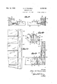
slats, from "their correct' ihorizontal' placements; the provision of areadily andeasily adjustable various other assemblyexpedieritsiand hardware. items, as well asan improved general' arrangee. o n eildi n'l me q s Other bbi e i appear from the following detailed description'of a presentlypreferred exemplary embodiment/0t the invention, considered in connection'with the accompanying drawings," idwhich'i Fig. 1 is'a front} elevation ot'a'vene tian blind' assembly embodying the present improvements,
in this figure "an irregular angular arrangement 1 of some of the partsbeing exaggerated-for better illustration Fig. 2 1s averticalfside elevation of the blind assemblyshown :by Fig 1; Fig.1- 3
. 25 ture and in the arrangement andconstruction of is a vertical section through the assembly, as viewed along line 3-3 of Fig. 1; Fig. 4 is a horizontal sectional elevation of the assembly of Fig. 1, as viewed along line 4-4 thereof Figs. 5 and 6 are, respectively, 'a vertical section and an isometric or perspective view of an adjustable brackat or hanger forthe tilting assembly; Fig. 'l is a fragmentary elevation in perspective of an improved adjustable corner bracket such'as preferably employed for connecting the head rail and each of the vertical or guide rails; Fig. 8 is a horizontal sectional elevation as viewed valongline 8-8 of Fig. l, and illustrating particularly the lift bar and appurtenances; Fig. 9 is an end elevation of the lift her showing particularly the v adjustable metal tenon and means for insuring automatic leveling ,of the} bar, asv well asthe means for anchoring the fiexiblelifting element such as a wire, to the liftlbar structure; Fig. 10 is an isometric view of the adjustable metal tenon, showing also' the automatically extensible features from which, result the self-locking properties of the lift barf, and Fig. 11 isa fragmentary plan view or development, illustrating the lighttight andlapping relation of the adjacent slats, ,when tilted to preclude vision or the entrance of light. a
Referring. now by characters .of reference to ,the drawings, there is indicated at 20, (Fig. 1),
the. usual windowfsill, extending'vertically from the opposite ends of which; arefthe jambs (not shown), and adjacentandparallel to which are secured the vertical guide rails 2| and 22. The
latter are connected by a transverse .head rail bridging their upper ends, and designated at 23.
The preferred form of connection embodying the brackets, such as 24 and 25, is hereinafter describedin more detail.
Suspended from the headrail .23, as by adjustable hangers 25 'and.2l is the'tilt rail28, provided, preferably at one -end,'with a worm and worm gear type. of tilt mechanism indicated generally at 2 9, and actuated as through an endless .chain or thelike, 30. The severalslats 35 1 are suspended in vertically [spaced relation as by a means of a plurality. of laddertapes 36, which are preferably of webbed textile construction,
and characterized by-somewhat heavy transverse cords 31 which extendiinparallel relation between the verticals of the ladder "tape, and
. which are transversely andsomewhat vertically separable so as to. permit' each offthe slats 35 to'be. brought'undersom'e. of the cords of each group as shown at 31, and supported by others, as at 38'. From this it will appear that as the blind is lifted iandthe slats are brought into adjacence, the intervening layer of cords will pre- Qclude direct impact of thejslats againsteach other, thus .protectingltheirf finish and cushion:
ing the adjacent slatmembers against rattling. irrespective of thespeed'of tilting, or raising" the assembly. .1
By preference theendslof the verticals of each of the ladder tapes are brought -into over-lapped relation and detachably secured'to the tilt rail or bar 28, as by a metal clip orthe like 40 (Fig. 3).
,The lower endfof {each of the'ladder tapes is .ladder tape substantially parallel at; all times.
It will appear from Fig. 1 that the tilting mech- Over the-pulley assembly 56.
anism 29, supporting as it does one end of the tilt bar 28, provides a rockable bearing for one endof the bar, while theb'racketfl provides a pivoting support for the opposite end. It is thus apparent that actuation of the tilt mechanism 29 as through chain 30, will impart a partial rotation to the tilt bar 28, in either direction, resulting in a tilting actuation of the several slats 35 in either direction from their normal position of repose, each in a'horizontal plane, to positions in-Which they are in partly over-lapped relation, resultingin a light-sealing closure asexemplified by Fig. 11.
By way of a general description of the as-' sembly for lifting the slats of the blind, it will appear from Fig. 1 that the li'ftvbar v42 is provided at each end witha laterally adjustable metal tenon assemblyj5l, hereinafter described in detail, and best'shown'by Fig. 9. To this assembly is anchored, as through a turnbuckle or the like 52, a flexible lifting element, preferably a stranded metal wire 53 of circular section, and
by further preference, formed of stainless steel toobviate the effects of rust or corrosion; The
be journalled on antifric'tion bearings, for ease of operation and silence as well as to minimize lubrication attention. It is further to 'be noted that the pulley 51 may be dispensed with, and that in this case both wires may be operated Infthis casejthe latter may be identical with the 'pulley assembly 54. 7 "It is further preferred,forconvenience of installation, that the pulleys 55, and'51 when utilized, be mounted in the guide rail bymeans of a common pulley casing engaging'the upper end of the right hand guide rail; in the assembly s Q 'It will have appeared that a downward movement of the swivel connection 58 to which is connected the wires 53, will result, because of the arrangement of pulleys; in a lifting; actuation of the bar 42 which, in turn, individually picks up and stacks the several slats.35 and '4I,"until-the blind is in'fully raised position. The aforesaid downward movement of the connection 5ll'is effected through downward movement of the adjacent end of the cord 59 which passes u'nder'and upwardly from a pulle'y; 55 mounted in a suitable pulley case 56. .Thecord thence continuesover a pulley'61, mounted in a suitable pulley case within and laterally of the right hand guide rall,
whence the cord extends outwardlythrough an automatic locking mechanism 10 (not shown in detail) whence there is exposed exteriorly of the blind assembly-a portion II to be engaged for lifting actuation.
In the case of a blind assembly which by reason 7 of abnormal length, height or for other reasons required agreater liftingenergy, the lifting actuation of the cord portion] I is conveniently compoundedby securing the ends of the round wires 5 53 to the case of a fall pulley (not shown).- The end of the operating cord may in this case be -attached tothe case of the fixed pulleyat the lower end of the assembly, thence passes over the fall pulley, thence downwardly to, and under the .10 lower fixed pulley, thence upwardly over the upper fixedpulley, and outthrough the locking'mechanism to aconvenient point .of actuation. The compounding structure is not presently. illustrated,l as involving only the addition of the fall pulley to the elements shown herein.
, Proceeding now to a description of certain of th features of improvementin the slat tenons; and guide provisions therefor,itwill best appear from Fig. 4 that theleft hand-guide rail 2| is provided m with a pair of inwardly presented, substantially verticalchannels I5 and 16. I In the latter of these operates ,the lifting wire 5 3, which isthus kept ,entirely'operatively independent of the slat tenons and slats, so as to prevent any possibility of g; ;interengagement with the wire, or fouling of either thereof. The channel 'I5is partly occupied by a longitudinally extending metal channelforming-element, preferably formed-of aluminum, and indicated generally at- TI. This is characterized by a pair of substantially parallel, resilient side portion I8, between which are' a pair of convergently related guide groove-forming ele- .ments .80, connectedat the bottom of the grooveas through'a bridge piece 8 I. As a means for '5 securing the metal channel-forming element 11 in the channel I5, the strip is provided with a lateral flange 85, which, at regularly spaced intervals, is apertured, the apertures each being of slotted form to engage anannular unthreaded undercut or reduced portion of a screw 86, which is threaded into the guide rail 2I. It will have appeared that the provision of the channel element lI, coacting with the screws 86, provides a guide-groove-forming member which maybe placed at different depths within the channel I5, and hence with respect to the guide rail 2I,. at any predetermined points between the sill and head rail of the window opening. v
The opposite guide rail 22 may, if desired, be provided witha similar channel-forming element such as H, but this is usually unnecessary since a single such element will usually provide a range of adjustment requisite to compensate for irregularities in width of the window opening between top and bottom, compensating as well for irregularity in angularity of the window-defining elements such as the jambs and sills. Accordingly, there is shown inthe assembly and in the detail of Fig. 4, a guidegroove 90 constituting a channel formed directly in the wood or other material of the guide rail 22. v This groove in the rail 22 preferably corresponds in shape, section and dimensions to that formed in the metal element 11. vThe rail 22 is further provided with a. second independent groove 9 I, for the reception of the lifting wire on this side of the assembly, and with channels 92 and 93 respectively, for the reception of cord portions 94 and-'95 consisting of parts of the lifting cord59 above described, and at times, portions of the lifting wire53 above referred to. It is importantly to be noted that the rail 22 is provided with a projection from its outside face, extending toward the center of the blind, and indicated at-IIlIl, and that theouter plate portion 7 'Ilof the metal guide channel is similarly-prowill best appear from Fig. 9 that the metal tenon assembly indicated generally at 5l- 1), in-
'vided, with a flange, I 0 I which projects. inwardly toward the center of the blind somewhat further the itenons of each jof the slats 35., the, ten ons being, indicatedat I05 and IIl6 respectively, on 10 the'left andright hand ends (Fig. ,4) of veach slat. These 'tenons are characterized by converging or V-shape outline in plan, thus conforming'in generalshape to each of the guide grooves. This offers a very distinct advantage 'in that,"due to 15- the substantially reducedwidthf of the extremities of the. tenons and the, bottoms of the. guide grooves, the operating clearance between the tenons and grooves-is scarcely greater'whenthe slats are tilted, than when occupying their horizontal I go positions. In this manner, even though'the slats be tilted to their fullest extent, there is minimized l the tendency forthe slats to rattlewithinithegrooves, due to windpressure and any other vibrating effects. The location of the-tenons disu tinctly rearwardly or back of thelongitudinal axis or center lineof each slat, results, when theslat is tilted, in a marked reduction/in tendency of the slats to be displaced, each about its ownaxis, under theinfluence of wind or other causes, thus 0 further reducing any tendency for -misalignment and rattling. It willfurther be-noted thata line connecting the lifting wires 53 (Fig, 1) is somewhat offset from the longitudinal axis or .medi an line of the slats. a 1 The preferencein mounting the blind, is to locate the projection I00 and projecting flange 1 II, on thestreet side or outside of the window, as distinguished from the inside or room side thereof. In this manner, as will best appear o fromFig. 11, which. illustrates the slats as they" would appear if tilted completely, the. line open ing-otherwise and usually remaining-at the ends of the slat, is covered, as by the projection I00, thus precluding the entrance of substantially any light, and rendering a vision-proof structure" which, besides offering all of the advantages of theVenetian blind, serves as acompletelsube stitute for window shades.
Proceeding now to a more complete description of the means by whichthe lift bar islrept horlzontal at all times in order to obviate casual 'tilting thereof, with resulting displacement of the slats from their desired horizontal position, it
cludes a mounting plate I I0 provided with a plurality o slotted screw apertures III, for the I reception of screws I I2, through which, the metal assembly may be secured at variable distances, endwise-of -thewoodportion of the bar 42in order; to-compensate for any irregularity in or departure from standard 'widths of window openings.
plate I 2Il.. .Since the pivots are ofi centerwith respectyto theplates I20, the provision; -oi-;an extraiaperture I'-I5A in-each plate- Ill, avoids the'necessity of separate right" and left-hand assemblies. .The plate I20 is provided witha v projection or tooth' l22, and an open-side aperture I25 for the reception of a bight or loop of the provisions by which, irrespective of angular "wire or the like I 26, engaging the turnbuckle 52 (Fig; 9)
Secured as by rivets I30,the plate I I3, is a leaf spring I3I tending to urge the plate I20 in a clockwise directioniFig. 10) about its pivot I15. I A second setof openings IA, are provided for the rivets I30, when the assembly is utilized at the opposite end of the bar. When in use the tension normally kept on the'wires 53 maintains the plates I20 in the positions shown blind, to disengage the bottom rail and hence the slats, by incorrect lifting attempts. It will have appeared that the metal'tenon assembly and the described self-lockingfeature combined therewith, attains the dual purpose of providing a lateral or endwise adjustable anchorage for assembling the-lifting wires to the lift bar, and also serves the noted purpose of preventing unequal lifting of the ends of the bar. 1
The immediately ensuing description refers to irregularities in the jambs, sills and the like defining the window, the blind assembly proper is 'kept so that its slats are in true, horizontal position. It will appear from Fig. 1; wherein is shown an exaggerated variation inheight of the window opening at its opposite sides, that the brackets 26 and 21 carried by the head rail 23,
permit easy-and positive leveling of the pivoted 1 Figs. 5 and 6, as preferably involving a pair of l..-'shaped brackets, one ofawhich is indicated at I40,'a horizontal leg portion of which is secured to the under surface of the head rail as through screws extending through the openings I. The vertical leg I42 of this bracket is provided with a plurality of adjustingapertures I43 for'the reception of a holding orlocking pin I45. The l tter constitutes a projection on a swingable or pivoted member I46 pivoted at I41 on a projection I48 carried by the second major element of the bracket structure which includes a vertical leg element I50 and a horizontal leg or plate element I5I. 'To one ofthe latter, as through slotted screw openings 152; is secured the hanger for the pivot on the free end of the tilt bar on the one side,and to another element I5I, the tilting mechanism such-as 29, on the other side of type, a prevalent difficulty exists in attaining'a' smooth joint and an even abutment between the vertical or guide r'ails'and the head rail, in win- "dow openings wherein the height of the opening is unequal at the opposite sides of the window, or wherein the top rail of the window and the jambs, are out of true rectangular relation, or the jambs are of unequal horizontal spacing in different parts of the window opening. Accordingly it has heretofore been impossible to precut at the time of manufacture,'either the'head rails to standard length, or the "guide rails to standard lengths, with any assurance of aneat corner construction. A
To overcome thisdefect and to minimize the time and labor of installation, the present Invention includes an improved corner fitting or connection piece, best illustrated by, Fig. 7. At the time of shipment the rail 23 is equipped with the fitting indicated generally at I60. This includes a plate-like portion I6I, secured asby screws I62 extending through horizontally 'slotted openings I63. The fitting I60-may thusbe adjusted right or left to the ends of the rail 23 in a mannerto compensate for any increase or decrease from standard width dimensions of the window opening. The adjustment possible is dependent of course, upon the'length of the slots- The elements I 65 and I66 are connected to the" plate portion I6I, as through a horizontal connecting piece I61, which, if desired, may extend somewhat about the end of the head rail, thereunder as far as desired, and for a more complete engagement with therail may also be extended over the top rail face. From .this'form of connection it will appear that even though the guide rail 2I is not brought into abutment with the under surface of the head rail, the resulting recess will nevertheless be concealed by the plate portions I65 and I66 and that, similarly, even though the head rail 23' be too short to fill fully the horizontal space in this portion of the window opening-the plate portion I6I' will nevertheless fill out and cover anyremaining' recess at the ends of the rail. It results that, in appearance, the finished structure will always be the same or substantially the same, irrespective of the described window irregularities. The fixture or connecting piece IE0 is formed of a fairlyrigid or heavysheet metal, which is nevertheless sufficiently flexible that when necessary, the rails 2I and 23 maybe brought somewhat out of per fect right angular relation without adversely affecting the appearance'of the corner connection or the strength of the joint in this-zone. It may here be noted that the'fitting shown by- Fig. 7
to those indicated generally by location, at 24 and 25in the assembly of Fig. l.
is substantially similar in all important respects 55 Although not necessary in many cases, in'the event of exaggerated misalignment or irregularities in the window elements, or whenotherwise desired for appearance of ornamentation, there may be applied'across the upper end of the blind assembly a valance board I10, which is conveniently secured in detachable relation-as byspring clips I1I, engaging the headrail'23. It will have appeared from the foregoing description that the assembly described results in a Venetian blind that constitutesa more permanent and definite part of the window, at the same time maintains a pleasing appearance, and is more practical and durable in service than the blinds of guided type as heretofore constructed.
Due to the special shape of the tenons on the slats, and the fact that these are, closely similar in shape to the section of the grooves, the tenons will always be reasonably tight, except only for a desirable working clearance, thus preventing any side motion of an extent'to cause noticeable noise. This is due in part to the fact that the present invention renders it possible for the first time, so far as is known, to be assured that each of the slat tenons enters its channel or guidewa'y, at the same depth in every part of the blind, and that all of the tenons of the different slats operate in the channels or guides with a uniform lateralclearance in any zone of their range of operation. v
Itwill also be apparent from the foregoing description thatby following the practice hereinabove outlined to afford the several adjustments described, it has become possible for the first time, so far as is known, to machinethe slats to lengths that assume a standard practice, rather than to lengths the exactness of which varies with each individual window opening,- according to the procedure heretofore prevalently followed.
It will further appear that the present invention offers an important improvement in the art in the marked reductionof time and skill required for successful and neat installation, irrespective of irregularities oi the elements defining the windows in and to which the blinds are installed.
It will have further appeared that the off-center placement and construction of the tenons, and the relation thereof to the guides, as well as the provision of the ledge or shoulder (such as I) provides for the first time, so far as is known, a substantially complete light seal when the blind slats are tilted fully to closed position, thus preventing vision through the formerly prevailing spaces at the ends of the slats, and completely precluding the transfer of light through the slats, when such condition is desired.
In addition to the foregoing outstanding advantages, it will appear that the invention fully attains each of the several objects hereinabove expressly enumerated, as well as those implied from the description of the example disclosed.
While the invention has been described by making specific reference to the assembly and the elements in their presently preferred form, such description is not to be understood in a limiting sense, since numerous changes may be made in the parts, as well as in their combinations and arrangements, without departing from the spirit and full intended scope of the invention as defined by the claims hereunto appended.
I claim as my invention:
1. In a Venetian blind assembly, in combination with the slats; a lift'rail therefor, a plurality of pulleys and flexible lifting elements operatively connected to the lift rail and operating over the pulleys, said lifting elements consisting of metal wire of stranded type, and being of substantially circular section, irrespective of reasonable twisting or torsional effects, whereby to assure uniform engagement of the wire with the pulleys at all times.
2. In a Venetian blind assembly, in combination with the slats, a pair of vertical rails at opposite sides of the assembly, slat-gliding means associated with the vertical rails, lifting mechan sm for the slats, including pulleysand flexible tension members operable over the pulleys, the lifting mechanism being mounted on and carried entirely by the vertical rails, a head rail bridging the vertical rails, and elements connecting the head rail to the vertical rails, and adapted to permit a limited angular and distance variation therebetween without affecting the lifting mechanism.
3. In a' frame structure for Venetian blinds of guided type including a pair of opposed vertical guide rails, a head rail connecting the guide rails, lifting means carried by the guide rails, and members connecting the head rail to the guide rails, so as to permit its connection to and removal from the guide rails without affecting the operation of the lifting means, said members being formed to permit an adjustment 'of the head rail distantly with respect to either of the guide rails.
4. In a Venetian blind of guided type including the slats together with lifting and tilting mechanism therefor, a pair of opposed vertical frame members each constructed to provide therein a pair of channels, one adapted to coact with the slats as a guide groove, and another adapted to house a flexible tension element for lifting the slats of the blind.
5. In a Venetian blind assembly, in combination with the slats, together with tilting and lifting mechanism therefor, a vertical element constituting a guide for the slats, means for adjusting said element in the plane of the window opening to which the blind is fitted, the tilting mechanism including a tilt rail from which the slats are suspended, hangers for the tilt rail and means for adjusting the length of said hangers to effect an angular adjustment of the tilt rail and elements suspended therefrom.
6. In a Venetian blind assembly of guided type, in combination with the slats together with tilting and lifting mechanism therefor, means forming a slat guide, means associated with said guide permitting its adjustment in a vertical plane, the lifting mechanism including a lift rail, a metal tenon on the lift rail, and means associated with the tenon permitting its adjustment endwise of the rail.
'7. In a Venetian blind assembly, in combination with the slats and tilting and lifting mechanism therefor, means forming a guide for the slats, means associated with the slat guide permitting its adjustment in a substantially vertical plane, a pair of vertical rails at the sides of the blind assembly, a head rail, a corner fitting connecting each of the verticalrails and the'head rail, and means associated with said fastening, permitting a variation in spacing and angularity of the headrail with respect to the adjacent vertical rail.
8. In a Venetian blind assembly, in'combination with the slats and lifting and tilting means therefor, the lifting means including a lift rail, a metal tenon at each end of the'liftrail adapted for adjustment endwise of the rail to vary the effective overall length thereof, a pair of vertical rails, a head rail connecting the vertical.
rails, and a fitting connecting each end of the head rail and the adjacent vertical rail, each fitting providing for a variation in spacing and angularity of the head rail and adjacent vertical rail.
9. In a Venetian blind assembly, in combination with the slats together with lifting and tilting mechanism therefor, a pair of vertical rails at opposite sides of the assembly, a head rail connecting the upper end portions of the vertical rails, a connecting member at each end of the head rail and including means permitting a variable distance placement of the head rail and associated vertical rail as well as a slight variation in angularity between said rails, said tilting mechanism including a tilt rail, endhang ers for the tilt rail, and means associated with said end hangers permitting the location and se- -slat guide, means associated therewith permitiingan adjustment of the slat guide in substanlift rail, means associated with said tenon elements permitting a variation in their placement endwise of the rail so as to vary the effective overall length of the liftrail, the tilting mechanism including a tilt rail, a pair of independently adjustable hangers for pivotally supporting the ends of the tilt rail and enabling the adjustment thereof to a horizontal position, a pair of vertical rails atopposite sides of the assembly, a head rail connecting the upper end portions of the vertical rails, and a corner connection at each end of the head rail, engaging the adjacent vertical rail, and means associated with each of said connections permitting a variation in rail distance placements, as well as a variation in angularity of the head rail and each of the side rails.
11. In a Venetian blind assembly of guided type, including a plurality of slats, tenons on the ends of the slats, means forming guide grooves for the tenons, the tenons and grooves each being of decreasing width, in a direction from the body of the slat toward the end of the tenon.
12. In a Venetian blind assembly of guided type, a plurality of slats, tenons on the ends of the slats, said tenons being disposed substantially off of the axis or longitudinal median line of each of the slats, and means forming a guide for each set of tenons,, the coacting guides and tenons being shaped to maintain a substantially uniform operating clearance about the tenons, irrespective of the angle of tilt of the slats.
13. In a Venetian blind assembly of guided type, a plurality of slats. tenons on the ends of the slats, said tenons being formed integrally with the slats, and disposed substantially off of the axis or longitudinal median line of each of the slats, and means forming a guide for each set of tenons, the coacting guides and tenons being shaped to maintain a substantially uniform operating clear ance about the tenons, irrespective of the angle of tilt of the slats.
, 1 In a Venetian blind assembly of guided type, in combination with the slats, tenons on the ends of the slats, means forming guide grooves for the tenons, lifting means for the slats including a pair of oppositely disposed flexible tension elements located beyond the ends of the slats, the tenons being located beyond or offset from the axes or longitudinal median lines of the slats, and the flexible lifting elements being arranged to operate in a plane beyond said median lines of the slats.
15. In a Venetian blind of guided type, including a plurality of slats and tenons on the slats, a stationary guide element for the tenons and a projection on said guide element presented toward the center of the blind, and adapted to be overlapped by the slats when in fully tilted position.
l6. In a Venetian blind assembly including a plurality of slats, tenons on the slats, means forming a guide element for the tenons, each of the slats being provided with an undercut or recess portion near at least one of its ends, a strip carried by the guide element adjacent the undercut portions of the slats, and adapted, in certain positions of the slats, to extend into said recess.
17. In a Venetian blind assembly including a plurality of slats, tenons on the slats, said tenons being of tapering width from the body of the slat toward the extremity of each of the tenons, means forming a guide element for the tenons, said guide element providing a groove of tapering width, corresponding substantially to the taper of the tenons engaged thereby, each of the slats bein provided with an undercut or recess portion 2% one of its ends, a stripcarried by the guide element adjacent the undercut portions of the slats, and adapted, in certain positions of the slats, to extend into said recess.
18. In a Venetian blind assembly of the guided type, including a plurality of slats, means forming a guide channel for end portions of the slats, lifting means for the slats including a pair of normally vertical flexible tension elements and a lift bar operatively engaged by said elements, the flexible tension elements being arranged to operate in a substantially vertical plane, substantially offset from the longitudinal median lines or axes of the several slats.
19. In a Venetian blind assembly including the slats together with lifting and tilting mechanism therefor, a lift bar constituting an element of the lifting mechanism, means forming a guide groove near each end of the lift bar, a tenon member carried by each end of the lift bar, and means associated with the tenons and bar, permitting an adjustment of the tenon member in a direction endwise of the bar.
20. In a Venetian blind assembly including the slats, lifting mechanism therefor including a lift bar, means forming guide grooves for the lift bar, located laterally of the bar and slats, elements carried near the ends of the bar, and each projecting into one of the guide grooves, resilient means tending to urge said elements into an extended relation endwise of the bar, and flexible lifting members operatively connected with said elements, for lifting the bar, and arranged, when under tension, to maintain the elements into a relatively retracted and operative relation with respect to said grooves.
21. In a Venetian blind assembly including the slats and lifting mechanism therefor including the lift bar,'means forming guide channels for the lift bar, elements pivotally mounted near the ends of the bar and each projecting into one of the guide channels, spring means tending to urge said pivoted elements about their pivots into a relatively extended relation and into engagement with wall portions of the guide channels whereby to support the bar therein, and flexible lifting members operatively connected with said elements and coacting therewith for lifting the bar, said lifting members being arranged, when under tension, to maintain the said elements in a relatively retracted position against said spring means, and in a position such that said elements will coact as tenons in guided relationto said channels.
22. In a Venetian blind assembly including the slats, and lifting mechanism therefor including a lift bar, means forming guide grooves for the lift bar, elements carried near the ends of, and endwise adjustable with respect to the bar, and each projecting into one of the guide grooves, spring means tending to bias said elements into an extended relation endwise of the bar, irrespective of their adjusted securement thereto, and flexible lifting members operatively connected with said elements for lifting the bar, and arranged when tensioned, to maintain said elements in a rela-v tively retracted and operative relation with respect to the grooves in which the elements operate.
23. In a Venetian blind assembly of guided type, including the slats and actuating mechanism therefor, a stationary, substantially vertical rail near one side of the assembly, adapted to be secured within a window opening to which the blind is fitted, a grooved member carried by the rail and coacting with the slats in guiding relation thereto, and means for adjusting different portions of said groove member into and out of parallelism with respect to said rail.
24. In combination with a Venetian blind assembly of guided type including the slats and lifting mechanism therefor, a vertical rail secured at one side of the blind and provided with a groove, and a grooved member extending into the groove of the rail, and providing a slat-guide channel, said grooved member being adjustable depthwise with respect to the groove in said rail.
25. In combination with a Venetian blind assembly of guided type including the slats and lifting mechanism therefor, a vertical rail secured at one side of the blind and provided with a groove, and a grooved member extending into the groove of the rail and providing a guide channel for the blind, said grooved member being adjustable depthwise with respect to the groove in said rail, the grooved member being laterally resilient and approximating in width, the width of the groove in the vertical rail, whereby said member is compressible into the rail groove in variable angular relations to the rail.
26. In combination in a Venetian blind assembly of guided type, a vertical rail at one side of the assembly, provided with a longitudinal recess, and an elongate metal member of channel section, so disposed that its channel will guidingly engage an end portion of the slats, and means spaced along the metal channel member for positively securing its different zones in predetermined angular relation with respect to the vertical rail.
27. As an article of manufacture, a metal guide element of channel section adapted for use in guidingly engaging the end of slats of Venetian blinds, the element being characterized by a pair of oppositely disposed substantially parallel side members, and an intervening tapered-channel forming portion.
28. As an article of manufacture, a channeled strip formed of metal for guidingly engaging the end portions of the slats of Venetian blinds, the strip being characterized by a channel which is symmetrical in transverse section, and a projection from said channel forming portion, extended in a direction toward the center of the associated blind, and adapted to be overlapped by portions of the slats when tilted, so as to provide a lightseal therewith, in the end zones of the slats.
29. As an article of manufacture, a channeled aluminum strip adapted for mounting in a substantially vertical position for guiding coaction with the ends of Venetian blind slats, the strip including a plurality of apertured lateral projections, a screw element extended through the aperture of each projection, the screws each having an annular groove so as to provide an unthreaded portion operable within the associated projection and engaging its opposite sides for adjusting movement, whereby the strip may be adjustably secured with its different zones in different angular relation to the adjacent portion of the'vertical rail or the like.
30. In combination with a Venetian blind assembly, together with the slats and tilting mechanism therefor, including a pivoted tilt bar, an anchorage plate, a plate for supporting the tilt bar, and means for securing said plates in predetermined, variable spaced relations.
31. The combination in a Venetian blind together with the slats and tilting mechanism therefor, including a pivoted tilt bar, an anchorage plate for supporting the tilt bar in pivoted relation, and including a flat member for securement to a supporting surface above the bar, a depending leg carried by said flat member and provided with a plurality of vertically spaced apertures, a support plate for the pivot forming structure and tilt bar, and means on said support plate for selective engagement with said apertures, whereby to provide a variation in vertical spacing of the support plate and the overlying support.
32. An adjustable hanger for the tilt bar of a Venetian blind assembly, including a pair of L- shaped elements each comprising a normally horizontal leg and a normally vertical leg, the horizontal legs adapted respectively for secure ment to an overlying horizontal support, and for a pivot-forming structure carrying the tilt bar, one of the vertical legs being provided with a plurality of vertically spaced apertures, and a pivotally-mounted pin carried by the other said vertical leg, and adapted selectively for engagement with said apertures to provide for a variation in vertical spacing of the horizontal legs, and means associated with at least one of the vertical legs for maintaining them in slidably associated assembly. I
33. In a Venetian blind assembly of a type including vertical and horizontal frame elements such as vertical rails and a head rail, a fitting for connecting the angularly related frame elements, said fitting including parts forming a pair of substantially rectangularly related seats, the fitting being provided with apertures for fastening means, at least some of said apertures being of elongate form and coacting with the fastening means to'enable an adjustment of 'the fitting, in a direction endwise of one of the frame elements to be secured in assembly thereby.
34. As an article of manufacture, a corner bracket for joining in assembly a vertical rail and a head rail of a Venetian blind frame, said bracket including a pair of substantially rectangularly related elements forming seats adapted at least partially to embrace the ends of the rails to be connected thereby.
35. As an article of manufacture, a corner bracket for joining in assembly a vertical rail and a head rail of a Venetian blind frame, said bracket including a pair of substantially rectangularly related elements forming pockets adapted to embrace the ends of the rails to be connected thereby, at least one of said pocket-forming portions being provided with slotted screwreceiving openings, whereby to permit a variable endwise placement of the fitting With respect to at least one of the rails to be assembled by means of the fitting.
Priority Applications (1)
| Application Number | Priority Date | Filing Date | Title |
|---|---|---|---|
| US137292A US2139781A (en) | 1937-04-16 | 1937-04-16 | Venetian blind |
Applications Claiming Priority (1)
| Application Number | Priority Date | Filing Date | Title |
|---|---|---|---|
| US137292A US2139781A (en) | 1937-04-16 | 1937-04-16 | Venetian blind |
Publications (1)
| Publication Number | Publication Date |
|---|---|
| US2139781A true US2139781A (en) | 1938-12-13 |
Family
ID=22476694
Family Applications (1)
| Application Number | Title | Priority Date | Filing Date |
|---|---|---|---|
| US137292A Expired - Lifetime US2139781A (en) | 1937-04-16 | 1937-04-16 | Venetian blind |
Country Status (1)
| Country | Link |
|---|---|
| US (1) | US2139781A (en) |
Cited By (9)
| Publication number | Priority date | Publication date | Assignee | Title |
|---|---|---|---|---|
| US2759534A (en) * | 1953-05-25 | 1956-08-21 | Walter A Harju | Vertical slat venetian blind |
| WO1997036081A1 (en) * | 1996-03-28 | 1997-10-02 | Lafayette Venetian Blind, Inc. | Venetian blind for palladian-style window |
| US20120097343A1 (en) * | 2010-10-26 | 2012-04-26 | Basileia Investments, Inc. | Venetian blind system |
| US8672146B1 (en) * | 2008-12-31 | 2014-03-18 | Douglas L. Cole | Neckwear and jewelry storage device |
| US10378787B2 (en) | 2010-07-14 | 2019-08-13 | Zhihua Fang | Dry open window (DOW) apparatus |
| US10386090B2 (en) * | 2010-07-14 | 2019-08-20 | Zhihua Fang | Reconfigurable system allowing air flow through an open window while blocking precipitation |
| US10876759B2 (en) | 2010-07-14 | 2020-12-29 | Zhihua Fang | Dry open window (DOW) apparatus |
| US20240151102A1 (en) * | 2021-03-24 | 2024-05-09 | Zachary Sweitzer | Window blind automation device |
| US12502040B1 (en) * | 2024-09-24 | 2025-12-23 | Laura Jean Lovell | Bath towel suspension apparatus |
-
1937
- 1937-04-16 US US137292A patent/US2139781A/en not_active Expired - Lifetime
Cited By (11)
| Publication number | Priority date | Publication date | Assignee | Title |
|---|---|---|---|---|
| US2759534A (en) * | 1953-05-25 | 1956-08-21 | Walter A Harju | Vertical slat venetian blind |
| WO1997036081A1 (en) * | 1996-03-28 | 1997-10-02 | Lafayette Venetian Blind, Inc. | Venetian blind for palladian-style window |
| US6062291A (en) * | 1996-03-28 | 2000-05-16 | Lafayette Venetian Blind, Inc. | Venetian blind for palladian-style window |
| US8672146B1 (en) * | 2008-12-31 | 2014-03-18 | Douglas L. Cole | Neckwear and jewelry storage device |
| US10378787B2 (en) | 2010-07-14 | 2019-08-13 | Zhihua Fang | Dry open window (DOW) apparatus |
| US10386090B2 (en) * | 2010-07-14 | 2019-08-20 | Zhihua Fang | Reconfigurable system allowing air flow through an open window while blocking precipitation |
| US10876759B2 (en) | 2010-07-14 | 2020-12-29 | Zhihua Fang | Dry open window (DOW) apparatus |
| US20120097343A1 (en) * | 2010-10-26 | 2012-04-26 | Basileia Investments, Inc. | Venetian blind system |
| US8302653B2 (en) * | 2010-10-26 | 2012-11-06 | Basileia Investments, Inc. | Venetian blind system |
| US20240151102A1 (en) * | 2021-03-24 | 2024-05-09 | Zachary Sweitzer | Window blind automation device |
| US12502040B1 (en) * | 2024-09-24 | 2025-12-23 | Laura Jean Lovell | Bath towel suspension apparatus |
Similar Documents
| Publication | Publication Date | Title |
|---|---|---|
| CA2243150C (en) | Window blind or shade | |
| US2139781A (en) | Venetian blind | |
| US2260726A (en) | Lower rail for venetian blinds | |
| US2116357A (en) | Venetian blind | |
| US2170877A (en) | Venetian blind | |
| US3183547A (en) | Hinge and closure assemblies for windows and the like | |
| US2141502A (en) | Venetian blind | |
| US2535751A (en) | Venetian blind | |
| US6622770B1 (en) | Tape drum for venetian type blinds | |
| US2587756A (en) | Sheetsxsheet i | |
| US5004033A (en) | Gap bridging assembly for use with vertical blind assemblies | |
| US2276898A (en) | Venetian blind | |
| US5176193A (en) | Venetian blind slat construction | |
| US2582301A (en) | Venetian blind | |
| US2553738A (en) | Window construction | |
| US2495973A (en) | Venetian blind | |
| US1894730A (en) | Anchor bracket | |
| US2387419A (en) | Venetian blind | |
| US2821247A (en) | Venetian blind | |
| US2198187A (en) | Venetian blind cord lock | |
| US2292001A (en) | Venetian blind construction | |
| US785806A (en) | Curtain-fixture. | |
| US2562259A (en) | Venetian blind | |
| US2258318A (en) | Window accessory | |
| US2059047A (en) | Venetian blind guide construction |