US2139752A - Copying apparatus - Google Patents
Copying apparatus Download PDFInfo
- Publication number
- US2139752A US2139752A US563260A US56326031A US2139752A US 2139752 A US2139752 A US 2139752A US 563260 A US563260 A US 563260A US 56326031 A US56326031 A US 56326031A US 2139752 A US2139752 A US 2139752A
- Authority
- US
- United States
- Prior art keywords
- printing
- sheet
- openings
- points
- rows
- Prior art date
- Legal status (The legal status is an assumption and is not a legal conclusion. Google has not performed a legal analysis and makes no representation as to the accuracy of the status listed.)
- Expired - Lifetime
Links
- 238000007639 printing Methods 0.000 description 94
- 230000007246 mechanism Effects 0.000 description 33
- 230000009471 action Effects 0.000 description 8
- 238000004804 winding Methods 0.000 description 5
- 238000010276 construction Methods 0.000 description 4
- 238000010586 diagram Methods 0.000 description 4
- 230000000452 restraining effect Effects 0.000 description 4
- 238000012384 transportation and delivery Methods 0.000 description 4
- 230000001276 controlling effect Effects 0.000 description 3
- 230000001360 synchronised effect Effects 0.000 description 3
- 230000005540 biological transmission Effects 0.000 description 2
- 238000000034 method Methods 0.000 description 2
- 230000008569 process Effects 0.000 description 2
- 230000000979 retarding effect Effects 0.000 description 2
- OKTJSMMVPCPJKN-UHFFFAOYSA-N Carbon Chemical compound [C] OKTJSMMVPCPJKN-UHFFFAOYSA-N 0.000 description 1
- 230000004075 alteration Effects 0.000 description 1
- 229910052799 carbon Inorganic materials 0.000 description 1
- 230000008859 change Effects 0.000 description 1
- 239000011248 coating agent Substances 0.000 description 1
- 238000000576 coating method Methods 0.000 description 1
- 230000003111 delayed effect Effects 0.000 description 1
- 238000010017 direct printing Methods 0.000 description 1
- 230000000694 effects Effects 0.000 description 1
- 230000005611 electricity Effects 0.000 description 1
- 239000005337 ground glass Substances 0.000 description 1
- 238000009413 insulation Methods 0.000 description 1
- 239000000463 material Substances 0.000 description 1
- 238000011282 treatment Methods 0.000 description 1
- 230000000007 visual effect Effects 0.000 description 1
Images


Classifications
-
- H—ELECTRICITY
- H04—ELECTRIC COMMUNICATION TECHNIQUE
- H04N—PICTORIAL COMMUNICATION, e.g. TELEVISION
- H04N1/00—Scanning, transmission or reproduction of documents or the like, e.g. facsimile transmission; Details thereof
- H04N1/23—Reproducing arrangements
Definitions
- This invention relates in general to printing by electrical impulses, and while the invention will hereinafter be described as embodied in an oflice appliance, particularly adapted for the copying or reproduction of typewriting, printing, handwriting, maps, drawings, and other documents, it will be readily apparent that the invention is capable of employment for the printing by electrical impulses to produce original pictures of objects either in black and white or in graduated tones, and may be employed for direct printing, or for the printing at remote points by telephone connection or radio transmission.
- One of the important objects of the invention is the provision of an improved process of copying documents and an apparatus for the practice of such process, which Will permit rapid reproduction of typewriting, handwriting, printing, maps, drawings and other documents upon any desired receiving paper, and without requiring any special treatments, such for example as photo-sensitive coating of the receiving paper.
- Another important object of the invention is the provision of a copying apparatus of the character described, wherein the printing and copy ing will be accomplished by a plurality of point impressions, which may be all of like intensity and visual effect, so that the copy produced will be even and readily legible, independently of line imperfections in the original fromwhich the copy is being made.
- point impressions which may be all of like intensity and visual effect
- gradations of printing may be accomplished so that from certain aspects of the invention confinement of patent is not desired in this regard.
- Another important object of the invention is the provision of an oflice copying apparatus, which is, or may be, of compact form and readily portable.
- Another important object of the inventionv is the provision of an apparatus of the character described, which will be Wholly automatic in its action, and which will not require particular skill or training for its operation.
- Another important object of the invention is the provision of an apparatus of the character described, which may be constructed to provide one, two, three, or more simultaneous copies of a subject matter.
- Another important object of the invention is the provision of an apparatus of the character described, the action of which will be of extreme rapidity and certain and even in its impression.
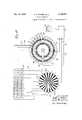
- Figure 1 is an end elevation of an apparatus embodying the present invention
- Fig. 2 is atop plan view thereof
- Fig. 3 is an enlarged plan view of a portion of the perforated sheet in the scanning device
- Fig. 4 is a section taken substantially on the line 4-4 of Fig. 3;
- Fig. 5 is a section taken substantially on the line 55 of Fig. 7;
- Fig. 6 is an enlarged vertical section through one of the magnets at the printing point
- Fig. 7 is an enlarged vertical section through the point printing mechanism, certain of the magnets being shown in section and certain of the magnets being shown in elevation;
- Fig. 8 is a partial elevation of the point printing mechanism
- Fig. 9 is a view similar to Fig. 6, showing a magnet of somewhat different construction.
- Fig. 10 is a schematic wiring diagram of the control provided for the point printing mechanism.
- the instant embodiment of the invention contemplates the scanning of a document, or other sheet to be reproduced, by an apparatus which divides the area of the sheet into minute sections individually inspected in the scanning, so that each individual section, preferably of an area of about square, controls point printing upon a receiving sheet in accordance with the scanning.
- the scanning device includes a plate arranged over the matter to be copied, andprovided with a plurality of perforations arranged in rows transversely of the sheet, as may be observed by comparing Figs. 2 and 3, wherein this perforated sheet is indicated by the reference character 2
- the perforations in each row are separated somewhat, and the perforations in the successive rows are progressively offset, as may be observed in Fig. 3.
- Relative movement is produced between the sheet to be copied and the plate, this movement preferably being accomplished by moving the scanning device and the plate over the sheet as the scanning progresses.
- the offsetting of the perforations of the various rows with respect to the perforations of other rows causes each minute part or section of the sheet being copied to appear separated at a perforation.
- a plurality of light beams of narrow width are successively moved 01' swung transversely of the sheet being copied, and directed through the presented perforations onto the exposed small areas of the original. If these areas be dark, i. e., if matter to be copied is presented at the perforations, point printing is accomplished upon the copy sheet by a magnetically impelled corressponding printing point, the magnetic points being arranged in accordance with the perforations in the plate 2! and the magnets controlled in accordance with the light reflection from the exposed areas at the perforations as the light beams are swung transversely and as the scanning and point printing mechanism is moved longitudinally over the sheets of original and copy.
- the apparatus shown on the drawings is mounted upon a suitable base, which may be of any preferred construction, and which is schematically indicated at 3!.
- This base is provided with an upwardly extending fixed bed 32, upon which the document to be copied (indicated at 33) is adapted to be arranged in fixed position.
- a second bed 34 also extends up from the base 3
- a carriage is adapted to move longitudinally of the beds 32 and 34, and is provided with rollers 31 and 38, respectively mounted upon tracks 39 of the bed 32 and tracks 4
- Two scanning devices 42 are mounted on the carriage above the bed 32, each of which is adapted to scan a transverse half of the original sheet.
- a point printing mechanism 43 is mounted above the bed 34, and provides the printing mechanism for producing imprinting upon the copy sheet in accordance with the scanning devices 42.
- is arranged in the carriage in close adjacent relationship to the upper face of the original sheet, and forms the lower part, or perforated wall, of the light chambers of the two scanning devices.
- the scanning devices are duplicates each of the other, except that one is arranged with its light directing elements at the left of the table or support 32, and the other at the right. A description of one of the scanning devices will be, it is believed, sufficient for an understanding of the two.
- a source of light 44 is mounted within the concentrating reflector 45, secured at 45 upon the carriage
- This source of light directs a confined bearn out through an opening 4'! and against a flange 48 of a revolving turret 49, which is provided with a plurality of condenser lenses 5!, adapted to be successively projected across and to transmit the light beam to a succession of mirrors 52, arranged at the upper ends of levers 53, which are pivoted at 54 on uprights 56, mounted on the carriage 35.
- the mirrors 52 reflect the light beam, which is generally indicated in dotted lines at 55, through an opening 55 in the top of a scanning chamber 51.
- a photo-electric cell 58 is mounted in this scanning chamber in a pocket 59 out of direct path of the light beam.
- Each lever 53 and its supported mirror 52 is swung as each condenser lens 5! passes it in the rotation of the turret 49, this being accomplished in the present instance by cams 6
- Rotation is imparted to the turrets 49 from a motor H, mounted upon a rearward extension 12 of the carriage.
- the motor shaft 73 is provided with a bevel gear 14, engaging a companion gear 15 upon a cross shaft 15, in turn provided with a bevel gear 11 meshing with companion gear 18, the turrets being driven by bevel gears 13 and 8!, as may be readily observed from the drawings.
- a worm or screw 89 is fixed in uprights B2, fastened to the base 3!, and is in thread engagement through the center of a gear 83, arranged through hub side bearings 84 in the carriage.
- the gear 83 is adapted to be continuously rotated by a pinion 85 fixed upon the motor shaft '13.
- the point printing mechanism which has been mentioned, is controlled in accordance with the scanning of the small sectional areas of the original to be copied, comprising a multiplicity of magnets each adapted to operate a printing point by impinging it against a printing ribbon or car-- bon sheet, the printing points being arranged in accurate accordance with the perforations of the scanning plate 2
- the printing point mechanism 43 compri es a frame 9
- the upper magnets are staggered with respect to the lower magnets 93 and control pin rods 94 having bearings through frame parts 95 and 96.
- the lower magnets 93 control pin rods 9'! having bearings through the bottom frame part 96.
- magnets 94 are shown in section and the pin rods 91 in plan. It will be noted that the magnets are arranged in transverse rows with the members of succeeding rows offset successively lengthwise of the apparatus, the offsetting being such that overlapping printing impressions are accomplished to reproduce a full line across the sheet.
- Each of the magnets of the instant embodiment of the invention is provided with two coils,
- the upper 98 is adapted to impel its printing pin or rod on a printing stroke, and the lower of which 99 is adapted to retard or prevent a printing stroke by opposing the effect of the magnet coil 98.
- Springs iii! are provided to return the pins or rods to upper position after a printing operation, and the magnet coils 99 of course must overcome the force of the springs IUI in printing.
- the current is periodically successively and in proper sequence supplied to the magnet coils 98, and unless the coils 99 be energized under the control of the photo-electric cells, printing 0ccurs at each periodical energization of each magnet coil 98.
- the magnet shown in Fig. 6 comprises the upper winding 98 disposed about an internal upper sleeve I92 and the winding 99 about an internal lower sleeve I93. These sleeves are separated by a box I94, within which is mounted a disc I95 on a rod I06 which separates the upper armature I 9'! and the lower armature I08, being interposed between their stems. Internal guide sleeves I69 may be provided if desired.
- the current deliveries are so timed that delivery of current to magnet coil 99 is delayed until after completion of the circuit delivering current to the companion coil 99. This permits a quick and early impression of the point if impression is to be permitted.
- the magnet structure shown in Fig. 9 comprises an inner member or core sleeve III, having an annular flange II 2, which spaces the upper winding 98 from the lower winding 99.
- the armatures I01 and I98 in this embodiment of the invention are separated by a non-magnetic rod H3, and the action of the'magnets is the same as that hereinbefore described.
- a printing ribbon is extended from rollers I22'and I23 carried upon the top of the frame 9
- reference character I3I indicates an electric generator mounted upon the carriage and driven by the motor shaft 13.
- This generator through suitable wiring to be present- 1y described, delivers actuating current to the successive magnets through a distributor mechanism.
- This distributor mechanism comprises two discs I32 fixed in upright position and loosely embracing a shaft I36 mounted in end bearings I31.
- a sleeve I35 is mounted upon the shaft I36 for independent rotation, and arms I34 are fixed upon the sleeve to rotate with it and move electric contacts I38 into successive engagement with contacts provided in the two discs I32.
- the sleeve I35 with its arms I34 is rotated continuously during the operation of the apparatus by gearing, which will now be described.
- a bevel gear I39 is fixed on the sleeve I35 and meshes with a bevel gear I40 upon the end of a shaft I which carries a bevel gear I42 in mesh with a gear I33 upon shaft 13. Successive engagement between the contacts I38 and the contacts on the discs I32 successively delivers energizing current to the coils 98, as will be presently more fully described.
- An interruptor for the circuits is provided to prevent delivery of current to any of the magnet coils between the active scanning actions.
- This interruptor comprises two discs I43, fixed in position with the shaft I36 extending through their centers.
- Two arms I46, having contacts I51, are fixed upon the, shaft I36 in such position that the. contacts I51 engage successively insulated segments of the disc I43 included in the magnet circuits.
- the shaft I36 is rotated in timed relation with the rotation of the sleeve I35, by a bevel gear I44 fixed upon the shaft I36, and a companion bevel gear I45 fixed upon the shaft I4I, already described.
- the mechanical devices employed to control delivery of current to the magnet coils 99 include the distributor and interruptor already described, contacts I13 being provided upon the arms I34, adapted to engage appropriately arranged and insulated contacts, mounted in the discs I32, and individually controlling the circuits to the coils 99 of the several magnets 92.
- the distributor and interruptor are each divided into two duplicated units, one disc I32 and one disc I43 being associated with and controlling half of the magnets 92.
- FIG. 10 A wiring diagram is illustrated in Fig. 10 and referring to this figure reference characters I5I and I52 indicate respectively positive and negative main line wires from a source of electricity, which in the instant embodiment is the generator I3I.
- Wire I5I is connected to contact I38 of arm I34.
- the contact I38 successively engages contacts I53 arranged circumferentially of the disc I32 and individually connected by wires I54 with upper cells 98 of the pin magnets 92.
- the coils 98 are in turn connected by wires I55 with segments I56 of disc I43.
- the arm I46 is provided with a contact I51 which successively rides over the segments I56 and is in turn connected to wire I52. Motivating current is thus provided successively to the coils 98 of the magnets 92 except when the contact I 51 is in engagement with the insulations 958 between the segments I56, which occurs between scanning of successive transverse rows of perforations 22, 23, 24, etc.
- a current is distributed or supplied successively to the coils 99 by circuits as follows:
- the photo-electric cell is indicated at 58 and it will be understood that this cell completes a circuit for an appropriate magnet coil 99 at the presentation of each white area in the perforaicns in the usual and known manner. Wiring diagram is not shown on the drawings for this since it is well known to those acquainted with photo-electric cells and photo-electric cell control. It may be mentioned, however, that the current change in the photo-electric cell occasioned by the reflection of the scanning device is amplified by a suitable amplifying device indicated generally by reference character I1I.
- the scanning may be accomplished by the projection of any desired image upon a ground glass, or even from a three dimensioned object.
- the force of impact of the pins in the printing may be controlled to give shaded results by varying the current in the coils 99 in accordance with variation in the reflection to the photo-electric cells.
- the embodiment of the invention hereinbefore described is particularly adapted for fast, ecos cal, and satisfactory copying in an organized t d of compact form.
- the invention however has other and more general use and application.
- a reproducing apparatus comprising in combination a support for the subject matter to be reproduced, a photo-electric cell, means successively directing light to successive areas of said subject matter for reflection to said photo-electric cell, and a printing mechanism comprising a plurality of printing points positioned to duplicate the arrangement of said areas, an inking medium for said points, and a plurality of magnets electrically controlled from said electric cell and in accordance with the reflection from said confined areas for actuating said printing points.
- a reproducing apparatus comprising a scanning device and a point printing mechanism.
- said scanning device comprising means for directing a beam of light successively to points spaced transversely of the matter being scanned and successive beams of light to intermediate transversely spaced points, a photo-electric cell receiving reflections from said points, and said point printing mechanism comprising a plurality of pointed members positioned to duplicate the arrangement of the points to which the light beams are directed, a plurality of magnets connected one to each of said members and arranged for control by said photo-electric cell in the order and arrangement of the points scanned by said scanning device.
- a reproducing apparatus comprising a scanning device and a point printing mechanism, said scanning device comprising a non-rotating rectangular plate perforated to provide rows of openings, the openings of each row being spaced transversely of the plate and the openings of successive rows being offset progressively longitudinally of the matter being scanned in overlapping relation, a photo-electric cell, and means directing a beam of light successively along said rows of perforations.
- a reproducing apparatus comprising a scanning device and a point printing mechanism, said scanning device comprising a plate perforated to provide rows of openings, the openings of each row being spaced transversely of the plate and the openings of successive rows being oflset progressively longitudinally of the matter being scanned in overlapping relation, a photo-electric cell, and means directing a beam of light successively along said rows of perforations, said means including a light concentrating member movable transversely of said rows of perforations.
- a reproducing apparatus comprising a scanning device and a point printing mechanism, said scanning device comprising a plate perforated to provide rows of openings, the openings of each row being spaced transversely of the plate and the openings of successive rows being offset progressively longitudinally of the matter being? scanned in overlapping relation, a photoelectric cell, and means directing a beam of light successively along said rows of perforations, said means including a light concentrating member and a plurality of reflecting mirrors, one for each row of perforations, for receiving a beam of light from said light concentrating member.
- a reproducing apparatus comprising a scanning device and a point printing mechanism, said scanning device comprising a plate perforated to provide rows of openings, the openings of each row being spaced transversely of the plate and the openings of successive rows being offset progressively longitudinally of the matter being scanned in overlapping relation, a photo-electric cell, and means directing a beam of light successively along said rows of perforations, said means including a light concentrating member and a plurality of mirrors one for each row of perforations, said mirrors swinging individually to move the beam of light lengthwise of its row of perforations.
- a reproducing apparatus comprising a scanning device having means for directing a confined beam of light to successive minute po'rtions of the matter being scanned, a photo-electric cell influenced in accordance with said scanning device, a point printing mechanism comprising a plurality of magnets, each provided with a printing point, said printing points being positioned to duplicate the arrangement of the respective minute portions of the matter being scanned, means supplying said magnets successively with impelling current to move the print.- ing points in a printing direction in sequence in accordance with the movement of said light beam, and an electric control for modifying the action of said magnets in turn controlled by said photo-electric cell.
- a reproducing apparatus comprising a scan: ning device having means for directing a confined beam of light to successive minute portions of the matter being scanned, a photo-electric cell influenced in accordance with said scanning device, and a point printing mechanism comprising a plurality of magnets, each provided with a printing point, said magnets being arranged in rows transversely of a receiving sheet, the members of successive rows being offset successively in overlapping relation.
- a reproducing apparatus comprising a scanning device having means for directing a con- ,f ned beam of light to successive minute portions of the matter being scanned, a photo-electric cell influenced in accordance with said scanning device, and a point printing mechanism comprising a plurality of magnets, each provided with 'a printing point, said magnets being arranged in rows transversely of a receiving sheet, the members of successive rows being offset successively in overlapping relation, and said magnets also being disposed in a plurality of planes at different distances from said receiving sheet.
- a machine for producing printed copies of typewritten, printed and other documents comprising, in combination, a first supporting means for a document to be copied, a second supporting means for a sheet to be printed, a scanning device associated with said first supporting means and comprising a screen positioned over said document and perforated to provide rows of openings, the openings of each row being spaced transversely of the screen, and the openings of the successive rows being offset progressively longitudinally of the screen in overlapping relation, means for directing a beam of light successively through said openings, and a photo-electric cell sensitive to reflected light from the document through said openings, a printing mechanism associated with said second supporting means and comprising a plurality of printing points arranged over said sheet in positions corresponding to the positions of said openings in said screen, means for reciprocating said points successively in timed relation to the passage of said beam of light through the corresponding openings arranged to cause the points, if unrestrained in their movement, to print on said sheet, means controlled by said photo-electric cell for restraining
- a machine for producing copies of typewritten, printed and other documents comprising, in combination, a first supporting means for a document to be copied, a second supporting means for a sheet to be printed, a scanning device associated with said first supporting means and comprising a rectangular screen perforated to provide rows of openings, the openings of each row being spaced transversely of the screen, and the openings of the successive rows being offset progressively longitudinally of the screen, means for directing a beam of light successively through said'openings, and a photo-electric cell sensitive to reflected light from the document through said openings, a printing mechanism associated with said second supporting means and comprising a plurality of printing points arranged over said sheet in positions corresponding to the positions of said openings in said screen, an inking medium positioned intermediate said points and said sheet, means for reciprocating said points successively in timed relation to the passage of said beam of light through the corresponding openings arranged to cause the points, if unrestrained in their movement, to print on said sheet, means controlled by said photo-electric cell for
- a printing mechanism comprising, in combination, a plurality of printing points positioned in a plurality of rows, the points of each row being spaced transversely of a sheet to be printed and "the points of successive rows being offset progressively longitudinally of the sheet in overlappingrelation, means for reciprocating said printing points successively at a predetermined frequency into printing engagement with said sheet so that during relative movement between said sheet and said points the points, if unrestrained, print over the entire surface of the sheet during a complete unidirectional passage of the sheet past the points, independent means for restraining the printing movement of each point, means for causing relative movement between the sheet and printing points, and an inking medium positioned intermediate the printing points and sheet.
- a printing mechanism comprising, in combination, a plurality of printing points positioned in a plurality of rows, the points of each row being spaced transversely of a sheet to be printed and the points of successive rows being offset progressively longitudinally of the sheet, means for reciprocating said printing points at a predetermined frequency into printing engagement with said sheet so that during relative movement between said sheet and said points the points, if unrestrained, print over the entire surface of the sheet, independent means for restraining the printing movement of each point, and means for causing relative movement between the sheet and printing points.
- a reproducing apparatus comprising, in combination, a scanning device having a nonrotating rectangular screen provided with rows of openings, the openings of each row being spaced transversely of the screen and the openings of successive rows being ofiset progressively longitudinally of the screen in overlapping relation, a photo-electric cell, means for directing a beam of light successively through said openings, and a point printing mechanism comprising a plurality of printing points, one for each opening in said screen, said printing points being spaced to duplicate the arrangement of said screen openings, and means for reciprocating said printing points in accordance with the reflected light from said screen openings controlled by said photo-electric cell.
- a reproducing apparatus comprising, in combination, a scanning device having a nonrotating screen provided with rows of openings, the openings of each row being spaced transverse- 1y of the screen and the openings of successive rows being offset progressively longitudinally of the screen, means for directing beams of light successively through said openings, and a point printing mechanism comprising a plurality of printing points, one for each opening in said screen, said printing points being spaced to duplicate the arrangement of said screen openings, an inking medium for said points, and means for actuating said printing points in accordance with the reflected light from said screen openings.
- a reproducing apparatus comprising, in combination, a mechanism for scanning a document to be reproduced, a mechanism for printing a copy of said document on a paper, said scanning mechanism comprising a screen positioned above the document and having a plurality of rows of openings, the openings of each row being spaced transversely of the screen, and the openings of successive rows being ofiset progressively longitudinally of the screen, a photo-electric cell subjected to refiected light from said openings, and means for directing a beam of light successively through said openings, said printing mechanism comprising a plurality of printing points, one for each of said openings, positioned in a plurality of rows to duplicate the positions of said screen openings, means for actuating said printinng points in synchronism with the passage of thelight beam through corresponding screen openings comprising a printing magnet, a retarding coil and a return spring for each point, means for energizing the printing magnets of said points in synchronism with the passage of the light beam through corresponding opening
- an ofiice appliance for reproducing intelligence on an original sheet to a copy sheet
- a first surface for an original sheet and a second surface for a copy sheet a screen overlying said first surface and the original sheet thereon for exposing increments of said original sheet'for scanning the same, said screen and said first surface being relatively movable with respect to one another
- a printing mechanism mounted over said second surface and the copy sheet thereon, said printing mechanism including a plurality of printing points, each of said points being located in a position with respect to said copy sheet to duplicate the position of one of the increments of said original sheet exposed by said screen, said printing points and said second surface being relatively movable with respect to one another, said relative movement being synchronized with the relative movement between said screen and said original sheet on said surfaces
Landscapes
- Engineering & Computer Science (AREA)
- Multimedia (AREA)
- Signal Processing (AREA)
- Facsimile Scanning Arrangements (AREA)
Description
Dec. 13, 1938. D. H. HOLMES ET AL COPYING APPARATUS Original Filed Sept. 17, 1931 5 Sheets-Sheet 1 Dec. 13, 1938. D. H. HOLMES ET AL 2,139,752
COPYING APPARATUS Original Filed Sept 17, 1931 5 Sheets-Sheet 2 Dec. 13, 1938.
D. H. HOLMES T AL COPYING AfPARATUS Original Filed Sept 17, 1931 5 Sheets-Sheet s WinYl/II/I/llfi/IIIII Dec. 13, 1938. D. H. HOLMES ET AL COPYING APPARATUS 5 Sheets-Sheet 4 Original Filed Sept. 17, 1931 u m /M/ m z J a G M1:
m M w W Dec. 13, 1938. D. HOLMES ET AL 2,139,752
COPYING APPARATUS Original Filed Sept. 17, 1931 5 Sheets-Sheet 5 a o 09 Q C) o h O0 ()6 Q w A Q Q g iw-mmjmws his Patented Dec. 13, 1938 UNITED STATES.
PATENT OFFICE COPYING APPARATUS of Illinois Application September 17, 1931, SerialNo. 563,260 Renewed January 12, 1938 17 Claims.
This invention relates in general to printing by electrical impulses, and while the invention will hereinafter be described as embodied in an oflice appliance, particularly adapted for the copying or reproduction of typewriting, printing, handwriting, maps, drawings, and other documents, it will be readily apparent that the invention is capable of employment for the printing by electrical impulses to produce original pictures of objects either in black and white or in graduated tones, and may be employed for direct printing, or for the printing at remote points by telephone connection or radio transmission.
One of the important objects of the invention is the provision of an improved process of copying documents and an apparatus for the practice of such process, which Will permit rapid reproduction of typewriting, handwriting, printing, maps, drawings and other documents upon any desired receiving paper, and without requiring any special treatments, such for example as photo-sensitive coating of the receiving paper.
Another important object of the invention is the provision of a copying apparatus of the character described, wherein the printing and copy ing will be accomplished by a plurality of point impressions, which may be all of like intensity and visual effect, so that the copy produced will be even and readily legible, independently of line imperfections in the original fromwhich the copy is being made. By slight. alteration in the current control, gradations of printing may be accomplished so that from certain aspects of the invention confinement of patent is not desired in this regard.
Another important object of the invention is the provision of an oflice copying apparatus, which is, or may be, of compact form and readily portable.
Another important object of the inventionv is the provision of an apparatus of the character described, which will be Wholly automatic in its action, and which will not require particular skill or training for its operation.
Another important object of the invention is the provision of an apparatus of the character described, which may be constructed to provide one, two, three, or more simultaneous copies of a subject matter.
Another important object of the invention is the provision of an apparatus of the character described, the action of which will be of extreme rapidity and certain and even in its impression.
Numerous other objects and advantages of the invention will be apparent as it is better understood from the following description, which, when taken in connection with the accompanying drawings, illustrates a preferred embodiment thereof.
Referring to the drawings,
Figure 1 is an end elevation of an apparatus embodying the present invention;
Fig. 2 is atop plan view thereof;
Fig. 3 is an enlarged plan view of a portion of the perforated sheet in the scanning device;
Fig. 4 is a section taken substantially on the line 4-4 of Fig. 3;
Fig. 5 is a section taken substantially on the line 55 of Fig. 7;
Fig. 6 is an enlarged vertical section through one of the magnets at the printing point;
Fig. 7 is an enlarged vertical section through the point printing mechanism, certain of the magnets being shown in section and certain of the magnets being shown in elevation;
Fig. 8 is a partial elevation of the point printing mechanism;
Fig. 9 is a view similar to Fig. 6, showing a magnet of somewhat different construction; and
Fig. 10 is a schematic wiring diagram of the control provided for the point printing mechanism.
The instant embodiment of the invention contemplates the scanning of a document, or other sheet to be reproduced, by an apparatus which divides the area of the sheet into minute sections individually inspected in the scanning, so that each individual section, preferably of an area of about square, controls point printing upon a receiving sheet in accordance with the scanning.
The scanning device includes a plate arranged over the matter to be copied, andprovided with a plurality of perforations arranged in rows transversely of the sheet, as may be observed by comparing Figs. 2 and 3, wherein this perforated sheet is indicated by the reference character 2|, and the transverse rows of perforations by the reference characters 22, 23, and 24, it being understood that a considerable number of these rows are provided. The perforations in each row are separated somewhat, and the perforations in the successive rows are progressively offset, as may be observed in Fig. 3.
Relative movement is produced between the sheet to be copied and the plate, this movement preferably being accomplished by moving the scanning device and the plate over the sheet as the scanning progresses. The offsetting of the perforations of the various rows with respect to the perforations of other rows causes each minute part or section of the sheet being copied to appear separated at a perforation.
A plurality of light beams of narrow width are successively moved 01' swung transversely of the sheet being copied, and directed through the presented perforations onto the exposed small areas of the original. If these areas be dark, i. e., if matter to be copied is presented at the perforations, point printing is accomplished upon the copy sheet by a magnetically impelled corressponding printing point, the magnetic points being arranged in accordance with the perforations in the plate 2! and the magnets controlled in accordance with the light reflection from the exposed areas at the perforations as the light beams are swung transversely and as the scanning and point printing mechanism is moved longitudinally over the sheets of original and copy.
With this preliminary general explanation of the instant embodiment of the invention, detailed description will now be undertaken.
The apparatus shown on the drawings is mounted upon a suitable base, which may be of any preferred construction, and which is schematically indicated at 3!. This base is provided with an upwardly extending fixed bed 32, upon which the document to be copied (indicated at 33) is adapted to be arranged in fixed position. A second bed 34 also extends up from the base 3| and provides a fixed support for the copy sheet 35, upon which reproduction of the original is to be accomplished.
A carriage, generally indicated at 36, is adapted to move longitudinally of the beds 32 and 34, and is provided with rollers 31 and 38, respectively mounted upon tracks 39 of the bed 32 and tracks 4| of the bed 34.
Two scanning devices 42 are mounted on the carriage above the bed 32, each of which is adapted to scan a transverse half of the original sheet. A point printing mechanism 43 is mounted above the bed 34, and provides the printing mechanism for producing imprinting upon the copy sheet in accordance with the scanning devices 42.
The perforated plate 2| is arranged in the carriage in close adjacent relationship to the upper face of the original sheet, and forms the lower part, or perforated wall, of the light chambers of the two scanning devices. The scanning devices are duplicates each of the other, except that one is arranged with its light directing elements at the left of the table or support 32, and the other at the right. A description of one of the scanning devices will be, it is believed, sufficient for an understanding of the two.
A source of light 44 is mounted within the concentrating reflector 45, secured at 45 upon the carriage This source of light directs a confined bearn out through an opening 4'! and against a flange 48 of a revolving turret 49, which is provided with a plurality of condenser lenses 5!, adapted to be successively projected across and to transmit the light beam to a succession of mirrors 52, arranged at the upper ends of levers 53, which are pivoted at 54 on uprights 56, mounted on the carriage 35.
The mirrors 52 reflect the light beam, which is generally indicated in dotted lines at 55, through an opening 55 in the top of a scanning chamber 51.
A photo-electric cell 58 is mounted in this scanning chamber in a pocket 59 out of direct path of the light beam. Each lever 53 and its supported mirror 52 is swung as each condenser lens 5! passes it in the rotation of the turret 49, this being accomplished in the present instance by cams 6| mounted on the turret, and which engage rollers 62 carried by the levers 53.
Viewing Fig. 2 it will be noted that there is a lever 53 for each row of perforations 22, 23, 24, etc. in the perforated plate, and in the rotation of the turret 49 a light beam is swung from the broken line position indicated at 63 to the broken line position indicated at 54 along each row of perforations and successively along the successive rows.
Rotation is imparted to the turrets 49 from a motor H, mounted upon a rearward extension 12 of the carriage. The motor shaft 73 is provided with a bevel gear 14, engaging a companion gear 15 upon a cross shaft 15, in turn provided with a bevel gear 11 meshing with companion gear 18, the turrets being driven by bevel gears 13 and 8!, as may be readily observed from the drawings.
Simultaneously with the rotation of the turrets the whole carriage is moved longitudinally of the document to be copied and of the copy sheet. A worm or screw 89 is fixed in uprights B2, fastened to the base 3!, and is in thread engagement through the center of a gear 83, arranged through hub side bearings 84 in the carriage. The gear 83 is adapted to be continuously rotated by a pinion 85 fixed upon the motor shaft '13. Thus geared the carriage is moved in synchronism with the successive projections of the light beam along the successive rows of perforations as the turrets 49 revolve. The swinging of the successive levers 53 occurs in close sequence and the timing is such that the reflection through each perforation may exert its individual influence upon the photoelectric cell.
It may be mentioned that it has been discovered that it is not necessary that there be a direct reflection from the mirror to the area exposed within the perforation and then up to the cell by arrangement of the light beam so that the angle of incidence is equal to the angle of reflection, the apparatus being sufliciently sensitive to permit controlling effect upon the photo-electric cell by the difference between a white and a dark area exposed through the individual perforation.
The point printing mechanism, which has been mentioned, is controlled in accordance with the scanning of the small sectional areas of the original to be copied, comprising a multiplicity of magnets each adapted to operate a printing point by impinging it against a printing ribbon or car-- bon sheet, the printing points being arranged in accurate accordance with the perforations of the scanning plate 2|.
Referring now more particularly to Fig. l, the printing point mechanism 43 compri es a frame 9| mounted upon the carriage and containing a set of upper magnets 92 and a set of lower magnets 93. The upper magnets are staggered with respect to the lower magnets 93 and control pin rods 94 having bearings through frame parts 95 and 96. The lower magnets 93 control pin rods 9'! having bearings through the bottom frame part 96.
The arrangement of these magnets is perhaps best illustrated in Fig. 5 wherein the pin rods 94 are shown in section and the pin rods 91 in plan. It will be noted that the magnets are arranged in transverse rows with the members of succeeding rows offset successively lengthwise of the apparatus, the offsetting being such that overlapping printing impressions are accomplished to reproduce a full line across the sheet.
Each of the magnets of the instant embodiment of the invention is provided with two coils,
one of which, namely the upper 98, is adapted to impel its printing pin or rod on a printing stroke, and the lower of which 99 is adapted to retard or prevent a printing stroke by opposing the effect of the magnet coil 98.
Springs iii! are provided to return the pins or rods to upper position after a printing operation, and the magnet coils 99 of course must overcome the force of the springs IUI in printing.
The current is periodically successively and in proper sequence supplied to the magnet coils 98, and unless the coils 99 be energized under the control of the photo-electric cells, printing 0ccurs at each periodical energization of each magnet coil 98.
Two different magnet and armature constructions are shown on the drawings, one of these being illustrated in Fig. 6 and the other in Fig. 9. The magnet shown in Fig. 6 comprises the upper winding 98 disposed about an internal upper sleeve I92 and the winding 99 about an internal lower sleeve I93. These sleeves are separated by a box I94, within which is mounted a disc I95 on a rod I06 which separates the upper armature I 9'! and the lower armature I08, being interposed between their stems. Internal guide sleeves I69 may be provided if desired.
When current is supplied to the coil 98 the armature I0! is attracted and presses down upon the rod I96, which in turn forces down the pin toward printing position. If current is supplied to the coil 99 under the influence of a photoelectric cell the armature I98 is attracted and printing prevented.
In order to secure certainty of action of the desired rapidity of printing stroke, the current deliveries are so timed that delivery of current to magnet coil 99 is delayed until after completion of the circuit delivering current to the companion coil 99. This permits a quick and early impression of the point if impression is to be permitted.
The magnet structure shown in Fig. 9 comprises an inner member or core sleeve III, having an annular flange II 2, which spaces the upper winding 98 from the lower winding 99. The armatures I01 and I98 in this embodiment of the invention are separated by a non-magnetic rod H3, and the action of the'magnets is the same as that hereinbefore described.
A printing ribbon, generally indicated by reference character I2I, is extended from rollers I22'and I23 carried upon the top of the frame 9|, this ribbon extending over guide rollers I24 at the top and guide rollers I25 at the bottom. In the operation of the apparatus this ribbon is successively passed over the receiving paper sheet 35, as is usual with typewriter and other similar ribbons.
A detailed showing or description of a ribbon feed is believed unnecessary to the instant invention, it being mentioned however that the ribbon passes between the printing pins and the sheet in the instant embodiment of the invention.
As has been stated, electric current is successively delivered to the upper coils 98 of all of the printing magnets independently of the scanning influence and in timed relation to the scanning actions.
Referring to Fig. 2, reference character I3I indicates an electric generator mounted upon the carriage and driven by the motor shaft 13. This generator, through suitable wiring to be present- 1y described, delivers actuating current to the successive magnets through a distributor mechanism. This distributor mechanism comprises two discs I32 fixed in upright position and loosely embracing a shaft I36 mounted in end bearings I31. A sleeve I35 is mounted upon the shaft I36 for independent rotation, and arms I34 are fixed upon the sleeve to rotate with it and move electric contacts I38 into successive engagement with contacts provided in the two discs I32. The sleeve I35 with its arms I34 is rotated continuously during the operation of the apparatus by gearing, which will now be described.
A bevel gear I39 is fixed on the sleeve I35 and meshes with a bevel gear I40 upon the end of a shaft I which carries a bevel gear I42 in mesh with a gear I33 upon shaft 13. Successive engagement between the contacts I38 and the contacts on the discs I32 successively delivers energizing current to the coils 98, as will be presently more fully described.
An interruptor for the circuits is provided to prevent delivery of current to any of the magnet coils between the active scanning actions. This interruptor comprises two discs I43, fixed in position with the shaft I36 extending through their centers. Two arms I46, having contacts I51, are fixed upon the, shaft I36 in such position that the. contacts I51 engage successively insulated segments of the disc I43 included in the magnet circuits. The shaft I36 is rotated in timed relation with the rotation of the sleeve I35, by a bevel gear I44 fixed upon the shaft I36, and a companion bevel gear I45 fixed upon the shaft I4I, already described.
The mechanical devices employed to control delivery of current to the magnet coils 99 (which are the coils controlled by the photo-electric cell 58), except for the wiring which is more particularly illustrated in Fig. 10, include the distributor and interruptor already described, contacts I13 being provided upon the arms I34, adapted to engage appropriately arranged and insulated contacts, mounted in the discs I32, and individually controlling the circuits to the coils 99 of the several magnets 92.
Because of the number of scanning actions and the number of magnets accordingly provided, the distributor and interruptor are each divided into two duplicated units, one disc I32 and one disc I43 being associated with and controlling half of the magnets 92.
A wiring diagram is illustrated in Fig. 10 and referring to this figure reference characters I5I and I52 indicate respectively positive and negative main line wires from a source of electricity, which in the instant embodiment is the generator I3I. Wire I5I is connected to contact I38 of arm I34. The contact I38 successively engages contacts I53 arranged circumferentially of the disc I32 and individually connected by wires I54 with upper cells 98 of the pin magnets 92. The coils 98 are in turn connected by wires I55 with segments I56 of disc I43.
The arm I46 is provided with a contact I51 which successively rides over the segments I56 and is in turn connected to wire I52. Motivating current is thus provided successively to the coils 98 of the magnets 92 except when the contact I 51 is in engagement with the insulations 958 between the segments I56, which occurs between scanning of successive transverse rows of perforations 22, 23, 24, etc.
A current is distributed or supplied successively to the coils 99 by circuits as follows:
The photo-electric cell is indicated at 58 and it will be understood that this cell completes a circuit for an appropriate magnet coil 99 at the presentation of each white area in the perforaicns in the usual and known manner. Wiring diagram is not shown on the drawings for this since it is well known to those acquainted with photo-electric cells and photo-electric cell control. It may be mentioned, however, that the current change in the photo-electric cell occasioned by the reflection of the scanning device is amplified by a suitable amplifying device indicated generally by reference character I1I.
Positive current is delivered through wire I12 to a contact In of rotating arm I34. Contact H3 is adapted for successive engagement with contacts I14, which are mounted on disc I32. Each of the contacts I14 is connected by a wire 35 with one side of the winding 99 in its companion magnet 92. The other side of the coil is in turn connected to the interrupter and through the interruptor to the negative side of the source of power to complete the circuit. On the wiring diagram shown in Fig. 10 this return is through the wires I55, segments I56, contact 55'? and wire I52.
It will be apparent that since the connection between the scanning device and the point printing mechanism is entirely electrical these units might be widely separated and the electric impulses transferred by telephone or by radio transmission, it only being necessary that the movement of the mechanical portions of the device be started and maintained with accurate timing and proceed at equal speeds.
Also it will be apparent, it is believed, that the scanning may be accomplished by the projection of any desired image upon a ground glass, or even from a three dimensioned object.
Also in the operation of the apparatus the force of impact of the pins in the printing may be controlled to give shaded results by varying the current in the coils 99 in accordance with variation in the reflection to the photo-electric cells.
The embodiment of the invention hereinbefore described is particularly adapted for fast, ecos cal, and satisfactory copying in an organized t d of compact form. The invention however has other and more general use and application.
It is thought that the invention and many of its attendant advantages will be understood from the foregoing description, and it will be apparent that various changes may be made in the form, construction and arrangement of the parts without departing from the spirit and scope of th invention or sacrificing all of its material advantages, the form hereinbefore described being merely a preferred embodiment thereof.
We claim:
1. A reproducing apparatus, comprising in combination a support for the subject matter to be reproduced, a photo-electric cell, means successively directing light to successive areas of said subject matter for reflection to said photo-electric cell, and a printing mechanism comprising a plurality of printing points positioned to duplicate the arrangement of said areas, an inking medium for said points, and a plurality of magnets electrically controlled from said electric cell and in accordance with the reflection from said confined areas for actuating said printing points.
2. A reproducing apparatus, comprising a scanning device and a point printing mechanism. said scanning device comprising means for directing a beam of light successively to points spaced transversely of the matter being scanned and successive beams of light to intermediate transversely spaced points, a photo-electric cell receiving reflections from said points, and said point printing mechanism comprising a plurality of pointed members positioned to duplicate the arrangement of the points to which the light beams are directed, a plurality of magnets connected one to each of said members and arranged for control by said photo-electric cell in the order and arrangement of the points scanned by said scanning device.
3. A reproducing apparatus, comprising a scanning device and a point printing mechanism, said scanning device comprising a non-rotating rectangular plate perforated to provide rows of openings, the openings of each row being spaced transversely of the plate and the openings of successive rows being offset progressively longitudinally of the matter being scanned in overlapping relation, a photo-electric cell, and means directing a beam of light successively along said rows of perforations.
4. A reproducing apparatus, comprising a scanning device and a point printing mechanism, said scanning device comprising a plate perforated to provide rows of openings, the openings of each row being spaced transversely of the plate and the openings of successive rows being oflset progressively longitudinally of the matter being scanned in overlapping relation, a photo-electric cell, and means directing a beam of light successively along said rows of perforations, said means including a light concentrating member movable transversely of said rows of perforations.
5. A reproducing apparatus, comprising a scanning device and a point printing mechanism, said scanning device comprising a plate perforated to provide rows of openings, the openings of each row being spaced transversely of the plate and the openings of successive rows being offset progressively longitudinally of the matter being? scanned in overlapping relation, a photoelectric cell, and means directing a beam of light successively along said rows of perforations, said means including a light concentrating member and a plurality of reflecting mirrors, one for each row of perforations, for receiving a beam of light from said light concentrating member.
6. A reproducing apparatus, comprising a scanning device and a point printing mechanism, said scanning device comprising a plate perforated to provide rows of openings, the openings of each row being spaced transversely of the plate and the openings of successive rows being offset progressively longitudinally of the matter being scanned in overlapping relation, a photo-electric cell, and means directing a beam of light successively along said rows of perforations, said means including a light concentrating member and a plurality of mirrors one for each row of perforations, said mirrors swinging individually to move the beam of light lengthwise of its row of perforations.
7. A reproducing apparatus, comprising a scanning device having means for directing a confined beam of light to successive minute po'rtions of the matter being scanned, a photo-electric cell influenced in accordance with said scanning device, a point printing mechanism comprising a plurality of magnets, each provided with a printing point, said printing points being positioned to duplicate the arrangement of the respective minute portions of the matter being scanned, means supplying said magnets successively with impelling current to move the print.- ing points in a printing direction in sequence in accordance with the movement of said light beam, and an electric control for modifying the action of said magnets in turn controlled by said photo-electric cell.
8. A reproducing apparatus, comprising a scan: ning device having means for directing a confined beam of light to successive minute portions of the matter being scanned, a photo-electric cell influenced in accordance with said scanning device, and a point printing mechanism comprising a plurality of magnets, each provided with a printing point, said magnets being arranged in rows transversely of a receiving sheet, the members of successive rows being offset successively in overlapping relation.
9. A reproducing apparatus, comprising a scanning device having means for directing a con- ,f ned beam of light to successive minute portions of the matter being scanned, a photo-electric cell influenced in accordance with said scanning device, and a point printing mechanism comprising a plurality of magnets, each provided with 'a printing point, said magnets being arranged in rows transversely of a receiving sheet, the members of successive rows being offset successively in overlapping relation, and said magnets also being disposed in a plurality of planes at different distances from said receiving sheet.
10. A machine for producing printed copies of typewritten, printed and other documents comprising, in combination, a first supporting means for a document to be copied, a second supporting means for a sheet to be printed, a scanning device associated with said first supporting means and comprising a screen positioned over said document and perforated to provide rows of openings, the openings of each row being spaced transversely of the screen, and the openings of the successive rows being offset progressively longitudinally of the screen in overlapping relation, means for directing a beam of light successively through said openings, and a photo-electric cell sensitive to reflected light from the document through said openings, a printing mechanism associated with said second supporting means and comprising a plurality of printing points arranged over said sheet in positions corresponding to the positions of said openings in said screen, means for reciprocating said points successively in timed relation to the passage of said beam of light through the corresponding openings arranged to cause the points, if unrestrained in their movement, to print on said sheet, means controlled by said photo-electric cell for restraining corresponding points from printing when the light beam striking corresponding openings of said screen pass over unprinted portions of said document, and means for causing relative and synchronous movement between said document and screen and between said sheet and printing device.
11. A machine for producing copies of typewritten, printed and other documents comprising, in combination, a first supporting means for a document to be copied, a second supporting means for a sheet to be printed, a scanning device associated with said first supporting means and comprising a rectangular screen perforated to provide rows of openings, the openings of each row being spaced transversely of the screen, and the openings of the successive rows being offset progressively longitudinally of the screen, means for directing a beam of light successively through said'openings, and a photo-electric cell sensitive to reflected light from the document through said openings, a printing mechanism associated with said second supporting means and comprising a plurality of printing points arranged over said sheet in positions corresponding to the positions of said openings in said screen, an inking medium positioned intermediate said points and said sheet, means for reciprocating said points successively in timed relation to the passage of said beam of light through the corresponding openings arranged to cause the points, if unrestrained in their movement, to print on said sheet, means controlled by said photo-electric cell for restraining corresponding points from printing when the light beam striking corresponding openings of said screen pass over-unprinted portions of said document, and means for causing relative and synchronous'move'ment between said document and screen and between said sheet and printing device.
12, A printing mechanism comprising, in combination, a plurality of printing points positioned in a plurality of rows, the points of each row being spaced transversely of a sheet to be printed and "the points of successive rows being offset progressively longitudinally of the sheet in overlappingrelation, means for reciprocating said printing points successively at a predetermined frequency into printing engagement with said sheet so that during relative movement between said sheet and said points the points, if unrestrained, print over the entire surface of the sheet during a complete unidirectional passage of the sheet past the points, independent means for restraining the printing movement of each point, means for causing relative movement between the sheet and printing points, and an inking medium positioned intermediate the printing points and sheet.
13. A printing mechanism comprising, in combination, a plurality of printing points positioned in a plurality of rows, the points of each row being spaced transversely of a sheet to be printed and the points of successive rows being offset progressively longitudinally of the sheet, means for reciprocating said printing points at a predetermined frequency into printing engagement with said sheet so that during relative movement between said sheet and said points the points, if unrestrained, print over the entire surface of the sheet, independent means for restraining the printing movement of each point, and means for causing relative movement between the sheet and printing points.
14. A reproducing apparatus comprising, in combination, a scanning device having a nonrotating rectangular screen provided with rows of openings, the openings of each row being spaced transversely of the screen and the openings of successive rows being ofiset progressively longitudinally of the screen in overlapping relation, a photo-electric cell, means for directing a beam of light successively through said openings, and a point printing mechanism comprising a plurality of printing points, one for each opening in said screen, said printing points being spaced to duplicate the arrangement of said screen openings, and means for reciprocating said printing points in accordance with the reflected light from said screen openings controlled by said photo-electric cell.
15. A reproducing apparatus comprising, in combination, a scanning device having a nonrotating screen provided with rows of openings, the openings of each row being spaced transverse- 1y of the screen and the openings of successive rows being offset progressively longitudinally of the screen, means for directing beams of light successively through said openings, and a point printing mechanism comprising a plurality of printing points, one for each opening in said screen, said printing points being spaced to duplicate the arrangement of said screen openings, an inking medium for said points, and means for actuating said printing points in accordance with the reflected light from said screen openings.
16. A reproducing apparatus comprising, in combination, a mechanism for scanning a document to be reproduced, a mechanism for printing a copy of said document on a paper, said scanning mechanism comprising a screen positioned above the document and having a plurality of rows of openings, the openings of each row being spaced transversely of the screen, and the openings of successive rows being ofiset progressively longitudinally of the screen, a photo-electric cell subjected to refiected light from said openings, and means for directing a beam of light successively through said openings, said printing mechanism comprising a plurality of printing points, one for each of said openings, positioned in a plurality of rows to duplicate the positions of said screen openings, means for actuating said printinng points in synchronism with the passage of thelight beam through corresponding screen openings comprising a printing magnet, a retarding coil and a return spring for each point, means for energizing the printing magnets of said points in synchronism with the passage of the light beam through corresponding openings, and means for energizing the retarding coils controlled by said photo-electric cell.
17. In an ofiice appliance for reproducing intelligence on an original sheet to a copy sheet, in combination, a first surface for an original sheet and a second surface for a copy sheet, a screen overlying said first surface and the original sheet thereon for exposing increments of said original sheet'for scanning the same, said screen and said first surface being relatively movable with respect to one another, a printing mechanism mounted over said second surface and the copy sheet thereon, said printing mechanism including a plurality of printing points, each of said points being located in a position with respect to said copy sheet to duplicate the position of one of the increments of said original sheet exposed by said screen, said printing points and said second surface being relatively movable with respect to one another, said relative movement being synchronized with the relative movement between said screen and said original sheet on said surfaces, means for scanning said original sheet and means controlled by said scanning means for imparting printing impulses from each increment of exposed intelligence to its respective printing point.
DWIGHT H. HOLMES. HARLEY T. BURGNER. EUGENE D. MACEWING.
Priority Applications (1)
| Application Number | Priority Date | Filing Date | Title |
|---|---|---|---|
| US563260A US2139752A (en) | 1931-09-17 | 1931-09-17 | Copying apparatus |
Applications Claiming Priority (1)
| Application Number | Priority Date | Filing Date | Title |
|---|---|---|---|
| US563260A US2139752A (en) | 1931-09-17 | 1931-09-17 | Copying apparatus |
Publications (1)
| Publication Number | Publication Date |
|---|---|
| US2139752A true US2139752A (en) | 1938-12-13 |
Family
ID=24249776
Family Applications (1)
| Application Number | Title | Priority Date | Filing Date |
|---|---|---|---|
| US563260A Expired - Lifetime US2139752A (en) | 1931-09-17 | 1931-09-17 | Copying apparatus |
Country Status (1)
| Country | Link |
|---|---|
| US (1) | US2139752A (en) |
Cited By (1)
| Publication number | Priority date | Publication date | Assignee | Title |
|---|---|---|---|---|
| US2875275A (en) * | 1954-05-10 | 1959-02-24 | Fairchild Camera Instr Co | Variable ratio photoelectric engraving machine |
-
1931
- 1931-09-17 US US563260A patent/US2139752A/en not_active Expired - Lifetime
Cited By (1)
| Publication number | Priority date | Publication date | Assignee | Title |
|---|---|---|---|---|
| US2875275A (en) * | 1954-05-10 | 1959-02-24 | Fairchild Camera Instr Co | Variable ratio photoelectric engraving machine |
Similar Documents
| Publication | Publication Date | Title |
|---|---|---|
| US3689149A (en) | Photographic printing apparatus having variable length print paper | |
| US3922484A (en) | Method for the rastered reproduction of colored continuous tone images of single or multicolor originals | |
| US4208666A (en) | Multiple copy ink jet printer | |
| US6211948B1 (en) | Process and apparatus for photomechanical production of structured surfaces, especially for irradiation of offset press plates | |
| US2287413A (en) | Facsimile system | |
| US2769922A (en) | Tape reading mechanism | |
| US2173488A (en) | Pattern-control mechanism | |
| US2139752A (en) | Copying apparatus | |
| US2160277A (en) | Photographic line-justifying apparatus | |
| US2881247A (en) | Step feed for electronic line scan and recording machines | |
| US2663232A (en) | Composing apparatus | |
| US2160951A (en) | Process and device for the reproduction of designs on printing plates by means of photoelectrically controlled gravers | |
| GB1411423A (en) | Process for the production of printing surfaces on printing images carriers | |
| US1776527A (en) | Machine for composing photographic prints | |
| US2982815A (en) | Facsimile transmitter | |
| US3012232A (en) | High speed printer | |
| US3109059A (en) | Device for producing halftone patterns | |
| GB763152A (en) | Improvements relating to apparatus for use in the examination of materials by x-ray diffraction | |
| US2258124A (en) | Communication system | |
| US2180638A (en) | Amusement apparatus | |
| US2767628A (en) | Photographic composing apparatus | |
| US3182333A (en) | Electrostatic high speed printer | |
| US4219850A (en) | Optical encoder | |
| US2619533A (en) | Permutation code printing receiver | |
| US3389398A (en) | High speed printing apparatus |