US2139653A - Syringe - Google Patents
Syringe Download PDFInfo
- Publication number
- US2139653A US2139653A US79070A US7907036A US2139653A US 2139653 A US2139653 A US 2139653A US 79070 A US79070 A US 79070A US 7907036 A US7907036 A US 7907036A US 2139653 A US2139653 A US 2139653A
- Authority
- US
- United States
- Prior art keywords
- barrel
- syringe
- fluid
- cavity
- bores
- Prior art date
- Legal status (The legal status is an assumption and is not a legal conclusion. Google has not performed a legal analysis and makes no representation as to the accuracy of the status listed.)
- Expired - Lifetime
Links
- 239000012530 fluid Substances 0.000 description 16
- 244000273618 Sphenoclea zeylanica Species 0.000 description 4
- 238000003780 insertion Methods 0.000 description 2
- 230000037431 insertion Effects 0.000 description 2
- 230000009286 beneficial effect Effects 0.000 description 1
- 238000010276 construction Methods 0.000 description 1
- 238000009826 distribution Methods 0.000 description 1
- 239000007788 liquid Substances 0.000 description 1
- 229920000136 polysorbate Polymers 0.000 description 1
- 230000002035 prolonged effect Effects 0.000 description 1
- 238000009827 uniform distribution Methods 0.000 description 1
- 239000002699 waste material Substances 0.000 description 1
Images
Classifications
-
- A—HUMAN NECESSITIES
- A61—MEDICAL OR VETERINARY SCIENCE; HYGIENE
- A61M—DEVICES FOR INTRODUCING MEDIA INTO, OR ONTO, THE BODY; DEVICES FOR TRANSDUCING BODY MEDIA OR FOR TAKING MEDIA FROM THE BODY; DEVICES FOR PRODUCING OR ENDING SLEEP OR STUPOR
- A61M3/00—Medical syringes, e.g. enemata; Irrigators
- A61M3/02—Enemata; Irrigators
- A61M3/0279—Cannula; Nozzles; Tips; their connection means
- A61M3/0283—Cannula; Nozzles; Tips; their connection means with at least two inner passageways, a first one for irrigating and a second for evacuating
-
- A—HUMAN NECESSITIES
- A61—MEDICAL OR VETERINARY SCIENCE; HYGIENE
- A61M—DEVICES FOR INTRODUCING MEDIA INTO, OR ONTO, THE BODY; DEVICES FOR TRANSDUCING BODY MEDIA OR FOR TAKING MEDIA FROM THE BODY; DEVICES FOR PRODUCING OR ENDING SLEEP OR STUPOR
- A61M1/00—Suction or pumping devices for medical purposes; Devices for carrying-off, for treatment of, or for carrying-over, body-liquids; Drainage systems
- A61M1/71—Suction drainage systems
- A61M1/77—Suction-irrigation systems
- A61M1/772—Suction-irrigation systems operating alternately
Definitions
- This invention relates to a syringe, and particularly to vaginal syringe adapted to be inserted into the cavity of the body for the purpose of conveying thereto a liquid or vapor for beneficial purposes.
- the principal object of this invention is the provision of a syringe so constructed as to direct the cleansing fluid in such a manner as to subject the walls of the cavity being treated to a thorough contact with the fluid.
- Another object of this invention is the provision of a syringe having a barrel with recesses formed in the outer surface thereof and means for introducing fluid into said recesses when the syringe is in position in the cavity, whereby the fluid is substantially equally distributed over the walls of the cavity.
- Figure 1 is an elevational view of a syringe embodying this invention.
- Fig. 2 is a longitudinal, sectional view, taken on line 11-11 of Fig. 1.
- Fig. 3 is an end elevation of the syringe.
- Fig. i is a cross sectional view, taken on line IV-IV of Fig. 2.
- Fig. 5 is an inside elevational View of the tip detached
- Fig. 6 is an elevation of the perforated washer.
- Fig. '7 is an elevational view of a modified form of the barrel.
- Fig. 8 is an enlarged, sectional view, taken on line VIIL-VIII of Fig. '7, and,
- Fig. 9 is a fragmentary, elevational View of a modified form of the barrel, in which each of the discharge perforations are provided with an individual recess in the surface of the barrel.
- the numeral IS indicates a syringe barrel of substantialiy cylindrical form provided with an enlarged, bell-shaped end 12, which is internally threaded at it.
- the outer end of the barrel is constructed with an open end l6 which is provided with internal threads 58. Openings formed through the wall of barrel iii communicate with the inner chamber 22 so as to permit fluids used in the treating operation to pass from the cavity to 22 where it is conveyed to the outlet, as hereinafter set forth.
- openings 20 are arranged in series which extend substantially parallel with the axis of the barrel. Between these series of openings, bores 23 are formed longitudinally in the wall of the barrel and serve to conduct the incoming fluid to the point of distribution. These bores extend entirely through said barrel and communicate with the inlet ports 38, which in turn communicates with the annular groove 32 that is formed in the inner end of handle 24.
- a washer 36 is positioned be tween the end of the hollow handle and the ends of channels 28. Openings 36, adapted to register with bores 28, serve to conduct the fluid from 32 to the respective bores.
- the inner chamber 22 communicates with outlet 38 through washer 3 5 and the recess 40 formed in the handle.
- This outlet 38 comprises a hollow stem 42 which is adapted to receive a rubber waste tube, not here shown.
- inlet port comprises a hollow stem 44 that is corrugated on its outside to receive a flexible tube such as is commonly used with a fountain syringe.
- a tip 46 having a concentrically disposed, threaded boss 48, is adapted to be securely positioned in the outer end of barrel Iii, with its outer periphery flush with the outer contour of the barrel, For convenience of insertion, this tip is rounded on its forward end.
- An annular groove 50 formed in the inner face of the tip, is adapted to register with the outer ends of bores 28.
- Tip 46 is provided with an'axially disposed opening 52 communicating with chamber 22, and a series of tubular openings 54 communicating withannular recess 56. These tubular openings are preferably positioned in a circle concentric with the axis of the barrel and so directed relative thereto as to intersect at a common point on the extended axis of the barrel when the axes of said tubular openings are prolonged.
- One of the principal features of this invention is to produce a structure wherein the treating fluid is directed, as nearly as possible, uniformly to all parts of the inner wall of the cavity being treated, and it is for this purpose that the re Memos 56 are formed in the outer face of the barrel wall.
- Each channel communicates with its adjacent recess through perforations 58 which are distributed in such a manner as to insure a proper flow of the treating fluid. It is the object of recesses 56 to maintain the wall of the cavity being treated away from the perforations 58. All of said wall spanning said recess will be contacted by said fluid and furthermore, said fluid will tend to move out from said recess in sheet form from each side of the recess, thereby insuring the greatest possible contact with the walls of the cavity.
- Fluid is also delivered through tubular openings 54 at the end of the barrel to treat tissues at the end of the cavity. All fluids so introduced will eventually be discharged through openings 20 and 54 to chamber 22 through washer 34 into recess 40, thence through the outlet port 38.
- a dam of any suitable form is adapted to snugly engage the outer wall of barrel I0 and to be adjusted thereon to limit the insertion of the barrel and to prevent the discharge of the spent fluid.
- the modified form of the barrel as shown in Figs. '7 and 8 provides for a combination of individual recesses 62, with elongated recesses 64 which communicate with a plurality of perforations 58. It will be noted that the recesses 64 are disposed in the cylindrical zones intermediate the ends of adjacent openings 2!). This particular structure is intended to control the flow of fluid in such a manner as to obtain uniform distribution thereof.
- the recesses '66 are similar to those shown at 62, thereby providing each perforation 58 with an individual distributing recess,
- a syringe comprising a tubular barrel having a plurality of longitudinally disposed bores formed therethrough from end to end thereof; a series of radially extending openings formed through the outermost wall of the barrel in communication with each bore respectively; a plurality of relatively large openings formed through the wall of said barrel intermediate said bores and in communication with the well of the barrel; a removable tip closing one end of the barrel, having an annular groove in communication with all of said bores at one end thereof, and provided with a number of tubular openings therethrough, all in communication with said annular groove and each being small in diameter with respect to the diameter of said bores, said tip having a relatively large axial opening formed therethrough in communication with the well of said barrel, said tubular openings being on a line circumscribing the said large axial opening; a removable handle closing the other end of the barrel having a circular cavity extending inwardly from one end thereof in communication and in longitudinal alignment with the well of said barrel and an annular groove in said one end circumscribing the
Landscapes
- Health & Medical Sciences (AREA)
- Heart & Thoracic Surgery (AREA)
- Life Sciences & Earth Sciences (AREA)
- Biomedical Technology (AREA)
- Anesthesiology (AREA)
- Hematology (AREA)
- Engineering & Computer Science (AREA)
- Animal Behavior & Ethology (AREA)
- General Health & Medical Sciences (AREA)
- Public Health (AREA)
- Veterinary Medicine (AREA)
- Pulmonology (AREA)
- Vascular Medicine (AREA)
- Infusion, Injection, And Reservoir Apparatuses (AREA)
Description
Patented Dec. 13, 1938 warren STATES PATENT orria 1 Claim.
This invention relates to a syringe, and particularly to vaginal syringe adapted to be inserted into the cavity of the body for the purpose of conveying thereto a liquid or vapor for beneficial purposes.
The principal object of this invention is the provision of a syringe so constructed as to direct the cleansing fluid in such a manner as to subject the walls of the cavity being treated to a thorough contact with the fluid.
Another object of this invention is the provision of a syringe having a barrel with recesses formed in the outer surface thereof and means for introducing fluid into said recesses when the syringe is in position in the cavity, whereby the fluid is substantially equally distributed over the walls of the cavity.
Other objects. of the invention are simplicity and economy of construction, ease and efllciency of operation and adaptability to various uses.
With these general objects, as well as others which will appear during the course of the specification, in view, reference will now be had to the drawing, wherein:
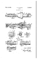
Figure 1 is an elevational view of a syringe embodying this invention.
Fig. 2 is a longitudinal, sectional view, taken on line 11-11 of Fig. 1.
Fig. 3 is an end elevation of the syringe.
Fig. i is a cross sectional view, taken on line IV-IV of Fig. 2.
Fig. 5 is an inside elevational View of the tip detached,
Fig. 6 is an elevation of the perforated washer.
Fig. '7 is an elevational view of a modified form of the barrel.
Fig. 8 is an enlarged, sectional view, taken on line VIIL-VIII of Fig. '7, and,
Fig. 9 is a fragmentary, elevational View of a modified form of the barrel, in which each of the discharge perforations are provided with an individual recess in the surface of the barrel.
Throughout the several views like reference characters designate similar parts, and the numeral IS indicates a syringe barrel of substantialiy cylindrical form provided with an enlarged, bell-shaped end 12, which is internally threaded at it. The outer end of the barrel is constructed with an open end l6 which is provided with internal threads 58. Openings formed through the wall of barrel iii communicate with the inner chamber 22 so as to permit fluids used in the treating operation to pass from the cavity to 22 where it is conveyed to the outlet, as hereinafter set forth.
Removably carried by barrel i0, is a hollow handle 24, provided at its open end with threads 25 which engage threads Hi. It will be observed that openings 20 are arranged in series which extend substantially parallel with the axis of the barrel. Between these series of openings, bores 23 are formed longitudinally in the wall of the barrel and serve to conduct the incoming fluid to the point of distribution. These bores extend entirely through said barrel and communicate with the inlet ports 38, which in turn communicates with the annular groove 32 that is formed in the inner end of handle 24.
In order to direct the fluid from 26 to the several bores 28, a washer 36 is positioned be tween the end of the hollow handle and the ends of channels 28. Openings 36, adapted to register with bores 28, serve to conduct the fluid from 32 to the respective bores. It will be observed that the inner chamber 22 communicates with outlet 38 through washer 3 5 and the recess 40 formed in the handle. This outlet 38 comprises a hollow stem 42 which is adapted to receive a rubber waste tube, not here shown. Also, inlet port comprises a hollow stem 44 that is corrugated on its outside to receive a flexible tube such as is commonly used with a fountain syringe.
A tip 46, having a concentrically disposed, threaded boss 48, is adapted to be securely positioned in the outer end of barrel Iii, with its outer periphery flush with the outer contour of the barrel, For convenience of insertion, this tip is rounded on its forward end. An annular groove 50, formed in the inner face of the tip, is adapted to register with the outer ends of bores 28. Tip 46 is provided with an'axially disposed opening 52 communicating with chamber 22, and a series of tubular openings 54 communicating withannular recess 56. These tubular openings are preferably positioned in a circle concentric with the axis of the barrel and so directed relative thereto as to intersect at a common point on the extended axis of the barrel when the axes of said tubular openings are prolonged.
One of the principal features of this invention is to produce a structure wherein the treating fluid is directed, as nearly as possible, uniformly to all parts of the inner wall of the cavity being treated, and it is for this purpose that the re cesses 56 are formed in the outer face of the barrel wall.
These recesses are preferably placed longitudinally of the barrel directly above bores 28. Each channel communicates with its adjacent recess through perforations 58 which are distributed in such a manner as to insure a proper flow of the treating fluid. It is the object of recesses 56 to maintain the wall of the cavity being treated away from the perforations 58. All of said wall spanning said recess will be contacted by said fluid and furthermore, said fluid will tend to move out from said recess in sheet form from each side of the recess, thereby insuring the greatest possible contact with the walls of the cavity.
Fluid is also delivered through tubular openings 54 at the end of the barrel to treat tissues at the end of the cavity. All fluids so introduced will eventually be discharged through openings 20 and 54 to chamber 22 through washer 34 into recess 40, thence through the outlet port 38. A dam of any suitable form is adapted to snugly engage the outer wall of barrel I0 and to be adjusted thereon to limit the insertion of the barrel and to prevent the discharge of the spent fluid.
The modified form of the barrel as shown in Figs. '7 and 8 provides for a combination of individual recesses 62, with elongated recesses 64 which communicate with a plurality of perforations 58. It will be noted that the recesses 64 are disposed in the cylindrical zones intermediate the ends of adjacent openings 2!). This particular structure is intended to control the flow of fluid in such a manner as to obtain uniform distribution thereof. In Fig. 9 the recesses '66 are similar to those shown at 62, thereby providing each perforation 58 with an individual distributing recess,
What I claim and desire to cover by Letters Patent is:
A syringe comprising a tubular barrel having a plurality of longitudinally disposed bores formed therethrough from end to end thereof; a series of radially extending openings formed through the outermost wall of the barrel in communication with each bore respectively; a plurality of relatively large openings formed through the wall of said barrel intermediate said bores and in communication with the well of the barrel; a removable tip closing one end of the barrel, having an annular groove in communication with all of said bores at one end thereof, and provided with a number of tubular openings therethrough, all in communication with said annular groove and each being small in diameter with respect to the diameter of said bores, said tip having a relatively large axial opening formed therethrough in communication with the well of said barrel, said tubular openings being on a line circumscribing the said large axial opening; a removable handle closing the other end of the barrel having a circular cavity extending inwardly from one end thereof in communication and in longitudinal alignment with the well of said barrel and an annular groove in said one end circumscribing the said cavity, said longitudinal bores being in communication with the circular cavity at their other ends; a radially extending hollow stem integral wi h the handle in communication with the circular cavity therein; and another radially extending hollow stem integral with the handle in communication with the cavity therein.
FRANK R. BELFRAGE.
Priority Applications (1)
| Application Number | Priority Date | Filing Date | Title |
|---|---|---|---|
| US79070A US2139653A (en) | 1936-05-11 | 1936-05-11 | Syringe |
Applications Claiming Priority (1)
| Application Number | Priority Date | Filing Date | Title |
|---|---|---|---|
| US79070A US2139653A (en) | 1936-05-11 | 1936-05-11 | Syringe |
Publications (1)
| Publication Number | Publication Date |
|---|---|
| US2139653A true US2139653A (en) | 1938-12-13 |
Family
ID=22148223
Family Applications (1)
| Application Number | Title | Priority Date | Filing Date |
|---|---|---|---|
| US79070A Expired - Lifetime US2139653A (en) | 1936-05-11 | 1936-05-11 | Syringe |
Country Status (1)
| Country | Link |
|---|---|
| US (1) | US2139653A (en) |
Cited By (22)
| Publication number | Priority date | Publication date | Assignee | Title |
|---|---|---|---|---|
| US2531793A (en) * | 1948-04-15 | 1950-11-28 | Sulek Steve | Hygienic syringe |
| US2568566A (en) * | 1946-05-06 | 1951-09-18 | Sokolik Edward | Surgical therapeutic appliance |
| US3225763A (en) * | 1962-06-18 | 1965-12-28 | Chesebrough Ponds | Medicinal injector |
| US3794031A (en) * | 1972-03-28 | 1974-02-26 | Rebold J | Electric douche |
| US3916896A (en) * | 1974-08-05 | 1975-11-04 | Alexander K S Ballard | Portable douche and sitz bath |
| US4195624A (en) * | 1978-06-09 | 1980-04-01 | Douglas Donald D | Tubular sheath for facilitating the insertion of an endoscope |
| US5242387A (en) * | 1992-05-08 | 1993-09-07 | Brigham & Women's Hospital | Suction-irrigator |
| US5300022A (en) * | 1992-11-12 | 1994-04-05 | Martin Klapper | Urinary catheter and bladder irrigation system |
| US6022329A (en) * | 1993-04-19 | 2000-02-08 | Stryker Corporation | Irrigation handpiece with built in pulsing pump |
| US6132405A (en) * | 1995-10-10 | 2000-10-17 | Gambro Ab | Catheter for peritoneal dialysis |
| US6213970B1 (en) | 1993-12-30 | 2001-04-10 | Stryker Corporation | Surgical suction irrigation |
| US6293928B1 (en) * | 1997-07-29 | 2001-09-25 | Medi Service S.R.L. | Cannula for vaginal irrigations |
| US20030036682A1 (en) * | 2001-08-03 | 2003-02-20 | Leber Leland C. | Nozzle for stoma cleansing system |
| US6595971B1 (en) | 1999-07-28 | 2003-07-22 | Zassi Medical Evolutions, Inc. | Ostomy irrigation system |
| US6746419B1 (en) | 1993-04-19 | 2004-06-08 | Stryker Corporation | Irrigation handpiece with built in pulsing pump |
| US20060084895A1 (en) * | 2004-10-19 | 2006-04-20 | Ariana Adjani | Vaginal cleansing and massaging device |
| US7481791B2 (en) | 2000-09-11 | 2009-01-27 | Stryker Corporation | Surgical suction irrigator |
| US20090163893A1 (en) * | 2003-06-05 | 2009-06-25 | Js Vascular, Inc. | Surgical drains |
| US20140135735A1 (en) * | 2012-04-05 | 2014-05-15 | Mark L. Anderson | Intra rectal/vaginal applicator technology |
| US8876754B2 (en) | 2006-08-31 | 2014-11-04 | Bayer Medical Care Inc. | Catheter with filtering and sensing elements |
| US20160303310A1 (en) * | 2015-04-17 | 2016-10-20 | ShineIN Biotechnology Co., Ltd. | Suction-irrigation head |
| US20210299401A1 (en) * | 2008-04-22 | 2021-09-30 | Becton, Dickinson And Company | Catheter hole having a flow breaking feature |
-
1936
- 1936-05-11 US US79070A patent/US2139653A/en not_active Expired - Lifetime
Cited By (28)
| Publication number | Priority date | Publication date | Assignee | Title |
|---|---|---|---|---|
| US2568566A (en) * | 1946-05-06 | 1951-09-18 | Sokolik Edward | Surgical therapeutic appliance |
| US2531793A (en) * | 1948-04-15 | 1950-11-28 | Sulek Steve | Hygienic syringe |
| US3225763A (en) * | 1962-06-18 | 1965-12-28 | Chesebrough Ponds | Medicinal injector |
| US3794031A (en) * | 1972-03-28 | 1974-02-26 | Rebold J | Electric douche |
| US3916896A (en) * | 1974-08-05 | 1975-11-04 | Alexander K S Ballard | Portable douche and sitz bath |
| US4195624A (en) * | 1978-06-09 | 1980-04-01 | Douglas Donald D | Tubular sheath for facilitating the insertion of an endoscope |
| US5242387A (en) * | 1992-05-08 | 1993-09-07 | Brigham & Women's Hospital | Suction-irrigator |
| US5300022A (en) * | 1992-11-12 | 1994-04-05 | Martin Klapper | Urinary catheter and bladder irrigation system |
| US6022329A (en) * | 1993-04-19 | 2000-02-08 | Stryker Corporation | Irrigation handpiece with built in pulsing pump |
| US7144383B2 (en) | 1993-04-19 | 2006-12-05 | Stryker Corporation | Surgical/medical irrigating handpiece with variable speed pump, integrated suction and battery pack |
| US6746419B1 (en) | 1993-04-19 | 2004-06-08 | Stryker Corporation | Irrigation handpiece with built in pulsing pump |
| US6623445B1 (en) | 1993-12-30 | 2003-09-23 | Stryker Corporation | Surgical suction irrigator |
| US6213970B1 (en) | 1993-12-30 | 2001-04-10 | Stryker Corporation | Surgical suction irrigation |
| US7297133B2 (en) | 1993-12-30 | 2007-11-20 | Stryker Corporation | Surgical suction irrigator |
| US6132405A (en) * | 1995-10-10 | 2000-10-17 | Gambro Ab | Catheter for peritoneal dialysis |
| US6293928B1 (en) * | 1997-07-29 | 2001-09-25 | Medi Service S.R.L. | Cannula for vaginal irrigations |
| US6595971B1 (en) | 1999-07-28 | 2003-07-22 | Zassi Medical Evolutions, Inc. | Ostomy irrigation system |
| US7481791B2 (en) | 2000-09-11 | 2009-01-27 | Stryker Corporation | Surgical suction irrigator |
| US20030036682A1 (en) * | 2001-08-03 | 2003-02-20 | Leber Leland C. | Nozzle for stoma cleansing system |
| US20090163893A1 (en) * | 2003-06-05 | 2009-06-25 | Js Vascular, Inc. | Surgical drains |
| US20060084895A1 (en) * | 2004-10-19 | 2006-04-20 | Ariana Adjani | Vaginal cleansing and massaging device |
| US7762997B2 (en) * | 2004-10-19 | 2010-07-27 | Ariana Adjani | Hygienic and therapeutic vaginal cleansing and hydromassaging device |
| US8876754B2 (en) | 2006-08-31 | 2014-11-04 | Bayer Medical Care Inc. | Catheter with filtering and sensing elements |
| US20210299401A1 (en) * | 2008-04-22 | 2021-09-30 | Becton, Dickinson And Company | Catheter hole having a flow breaking feature |
| US11752301B2 (en) * | 2008-04-22 | 2023-09-12 | Becton, Dickinson And Company | Catheter hole having a flow breaking feature |
| US20140135735A1 (en) * | 2012-04-05 | 2014-05-15 | Mark L. Anderson | Intra rectal/vaginal applicator technology |
| US10321982B2 (en) * | 2012-04-05 | 2019-06-18 | Mark L. Anderson | Intra rectal/vaginal applicator technology |
| US20160303310A1 (en) * | 2015-04-17 | 2016-10-20 | ShineIN Biotechnology Co., Ltd. | Suction-irrigation head |
Similar Documents
| Publication | Publication Date | Title |
|---|---|---|
| US2139653A (en) | Syringe | |
| US2257369A (en) | Catheter and drainage tube | |
| US5857991A (en) | Device for applying medication fluid on mucus membrane in body cavities | |
| US2624341A (en) | Catheter | |
| DK153522B (en) | ADJUSTABLE FLOW CONTROL | |
| US2631586A (en) | Rectal applicator and dilator | |
| US1633074A (en) | Surgical device | |
| US4301798A (en) | Vaginal syringe | |
| US2633729A (en) | Yarn tube | |
| US2507214A (en) | Vaginal syringe | |
| EP0405250B1 (en) | Resectoscope | |
| US877926A (en) | Vaginal syringe. | |
| US2802466A (en) | Syringe | |
| KR910004879A (en) | Apparatus for limiting dispersion of treatment liquid sprayed onto fabric | |
| US2618271A (en) | Surgical drain | |
| US3988112A (en) | Nozzle sterilizer providing outer and inner annular concentric cooling jets | |
| KR910003198A (en) | Syringes for liquids carried as gas fluids | |
| US2458719A (en) | Colonic device | |
| US2265080A (en) | Anus and vaginal irrigator | |
| US2565109A (en) | Fountain massage device | |
| US1852427A (en) | Dual tube nozzle | |
| US2835181A (en) | Fluid circulating film handling reel and tank | |
| US1365948A (en) | Irrigator | |
| US694541A (en) | Vaginal syringe. | |
| US3065750A (en) | Dilatable sanitary douche |